EP1052730B1 - Elément de connexion électrique pour un câble et méthode de montage - Google Patents
Elément de connexion électrique pour un câble et méthode de montage Download PDFInfo
- Publication number
- EP1052730B1 EP1052730B1 EP00109813A EP00109813A EP1052730B1 EP 1052730 B1 EP1052730 B1 EP 1052730B1 EP 00109813 A EP00109813 A EP 00109813A EP 00109813 A EP00109813 A EP 00109813A EP 1052730 B1 EP1052730 B1 EP 1052730B1
- Authority
- EP
- European Patent Office
- Prior art keywords
- terminal
- cable
- insulation coating
- coaxial cable
- positioning
- Prior art date
- Legal status (The legal status is an assumption and is not a legal conclusion. Google has not performed a legal analysis and makes no representation as to the accuracy of the status listed.)
- Expired - Lifetime
Links
- 238000000034 method Methods 0.000 title claims description 6
- 238000009413 insulation Methods 0.000 claims description 43
- 239000011248 coating agent Substances 0.000 claims description 42
- 238000000576 coating method Methods 0.000 claims description 42
- 238000003780 insertion Methods 0.000 claims description 8
- 230000037431 insertion Effects 0.000 claims description 8
- 238000005452 bending Methods 0.000 claims description 3
- 238000002788 crimping Methods 0.000 claims description 3
- 238000005728 strengthening Methods 0.000 claims description 2
- 238000010276 construction Methods 0.000 description 3
- 230000000694 effects Effects 0.000 description 2
- 239000000463 material Substances 0.000 description 2
- 239000002184 metal Substances 0.000 description 2
- 230000001419 dependent effect Effects 0.000 description 1
- 238000006073 displacement reaction Methods 0.000 description 1
- 238000004049 embossing Methods 0.000 description 1
- 238000010438 heat treatment Methods 0.000 description 1
- 238000003466 welding Methods 0.000 description 1
Images





Classifications
-
- H—ELECTRICITY
- H01—ELECTRIC ELEMENTS
- H01R—ELECTRICALLY-CONDUCTIVE CONNECTIONS; STRUCTURAL ASSOCIATIONS OF A PLURALITY OF MUTUALLY-INSULATED ELECTRICAL CONNECTING ELEMENTS; COUPLING DEVICES; CURRENT COLLECTORS
- H01R9/00—Structural associations of a plurality of mutually-insulated electrical connecting elements, e.g. terminal strips or terminal blocks; Terminals or binding posts mounted upon a base or in a case; Bases therefor
- H01R9/03—Connectors arranged to contact a plurality of the conductors of a multiconductor cable, e.g. tapping connections
- H01R9/05—Connectors arranged to contact a plurality of the conductors of a multiconductor cable, e.g. tapping connections for coaxial cables
- H01R9/0518—Connection to outer conductor by crimping or by crimping ferrule
-
- H—ELECTRICITY
- H01—ELECTRIC ELEMENTS
- H01R—ELECTRICALLY-CONDUCTIVE CONNECTIONS; STRUCTURAL ASSOCIATIONS OF A PLURALITY OF MUTUALLY-INSULATED ELECTRICAL CONNECTING ELEMENTS; COUPLING DEVICES; CURRENT COLLECTORS
- H01R9/00—Structural associations of a plurality of mutually-insulated electrical connecting elements, e.g. terminal strips or terminal blocks; Terminals or binding posts mounted upon a base or in a case; Bases therefor
- H01R9/03—Connectors arranged to contact a plurality of the conductors of a multiconductor cable, e.g. tapping connections
- H01R9/05—Connectors arranged to contact a plurality of the conductors of a multiconductor cable, e.g. tapping connections for coaxial cables
- H01R9/0515—Connection to a rigid planar substrate, e.g. printed circuit board
Definitions
- the present invention relates to a terminal for a cable, in particular a coaxial cable and to a method for mounting such a terminal on a cable.
- Coaxial cables have been used, for example, to receive high-frequency signals.
- an end of a coaxial cable is coupled to, for example, a printed circuit board
- a core is caused to project from a leading end of an inner insulation coating and a braided wire is folded back around the outer surface of an outer insulation coating at the end of the coaxial cable.
- a terminal for the coaxial cable to be electrically connected with only the braided wire is provided to connect the coaxial cable and the printed circuit board.
- the coaxial cable and the terminal therefor are fixed by crimping a barrel portion of the terminal after pushing the coaxial cable into the terminal along its longitudinal direction to position them with respect to each other.
- the mount positions of the terminals may vary along the longitudinal direction, thereby causing a variation of high-frequency characteristics.
- US 3 383 457 discloses a terminal to be connected with a coaxial cable, wherein a ferrule member is positioned on an insulation sheath of the cable for positioning the terminal on the cable.
- US 4 178 054 discloses a connector to be connected with a coaxial cable, wherein an inner insulation coating of the cable comes into contact with a positioning portion of a center contact of the connector.
- an object of the present invention is to provide a terminal for a cable, in particular a coaxial cable and a method for connecting such a terminal allowing for a stable mounting of the terminal at a predetermined position on a leading end of the cable.
- the terminal is mountable on a coaxial cable comprised of an inner insulation coating, a core projecting from the leading end of the inner insulation coating, an outer insulation coating, and a shield layer, preferably a braided wire, surrounding the inner insulation coating and at least partly folded back to be brought substantially into close contact with the outer surface of the outer insulation coating, wherein the barrel portion is to be crimped into connection with a folded section of the shield layer of the coaxial cable.
- a coaxial cable comprised of an inner insulation coating, a core projecting from the leading end of the inner insulation coating, an outer insulation coating, and a shield layer, preferably a braided wire, surrounding the inner insulation coating and at least partly folded back to be brought substantially into close contact with the outer surface of the outer insulation coating, wherein the barrel portion is to be crimped into connection with a folded section of the shield layer of the coaxial cable.
- the terminal further comprises a cover portion substantially continuously extending from the barrel portion so as to substantially cover the exposed core without being held in contact therewith.
- a terminal mountable on a coaxial cable comprised of an inner insulation coating, a core projecting from the leading end of the inner insulation coating, an outer insulation coating, and a braided wire surrounding the inner insulation coating and folded back to be brought into close contact with the outer surface of the outer insulation coating, comprising:
- the positioning portion is brought into contact with the coaxial cable to position the terminal with respect to the longitudinal direction of the coaxial cable, and the barrel portion is crimped into connection with the folded section of the braided wire in this state, with the result that the terminal can be stably mounted at a predetermined position on the coaxial cable. Since the terminal is stably mounted and the core is covered by the cover portion over a predetermined length, an electrical capacity between the core and the terminal is stabilized, thereby providing stable high-frequency characteristics.
- the cover portion is integrally or unitarily formed with one or more leg portions for mounting the terminal on a printed circuit board.
- the terminal can be easily mounted on the printed circuit board by forming the cover portion with the leg portions.
- the leg portions are provided with one or more embossed portions for strengthening the leg portions and/or for locking the leg portions in corresponding mount holes of the circuit board.
- leg portions are provided with stepped portions for coming into engagement with the circuit board upon insertion of the leg portions into mount holes of the printed circuit board.
- the barrel portion is formed with at least one inward projecting biting portion for biting in a portion of the cable, preferably in the shield layer, preferably braided wire thereof.
- biting portion bites in the shield layer or braided wire when the barrel portion is crimped into connection with the braided wire, a function of preventing a disengagement of the barrel portion from the coaxial cable can be strengthened.
- a projecting height of the biting portion is shorter than that of the positioning portion lest the biting portion should interfere the insertion of the cable or coaxial cable into the terminal.
- the coaxial cable can be smoothly inserted into the terminal without being interfered by the biting portion.
- the terminal is constructed such that the cable or coaxial cable is insertable into the terminal up to the cover portion from a barrel portion side along its longitudinal direction, and the positioning portion is formed by making a cut in the cover portion and bending the cut portion and is engageable a portion of the cable, preferably with the front end of the outer insulation coating which is a starting position of the folded section of the shielded layer or braided wire.
- biting portion and the positioning portion are arranged substantially opposing to each other along an arrangement direction of the cable.
- FIGS. 1 to 9 Next, one embodiment of the invention is described in detail with reference to FIGS. 1 to 9 .
- a side where a core 3 of the coaxial cable 2 is exposed is referred to as a front side in the description of this embodiment.
- the coaxial cable 2 is comprised of four layers and the core 3 is substantially centered inside.
- the core 3 is surrounded by an inner insulation coating 4; the inner insulation coating 4 is surrounded by a braided wire as a shield layer 5; and the braided wire 5 is surrounded by an outer insulation coating 6 at the outermost side.
- These four layers 3 to 6 are substantially coaxially arranged.
- terminal 1 At an end of the coaxial cable 2 to be connected with a terminal 1 for the coaxial cable (hereinafter, "terminal 1") to be described later, the outer insulation coating 6 is stripped, and the thus exposed braided wire 5 is at least partly folded back preferably to be held in substantially close contact with the outer surface of the outer insulation coating 6 such that a base end of a folded section or portion 5A of the braided wire 5 preferably substantially coincides with the front end of the remaining outer insulation coating 6.
- An exposed section of the inner insulation coating 4 is stripped up to a predetermined position before the folded portion 5A, and the core 3 projects from a leading end 4A of the remaining inner insulation coating 4.
- the end of the coaxial cable 2 thus processed may be referred to as "a stripped end” in the following description.
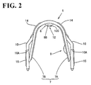
- FIG. 1 is a front view of the terminal 1.
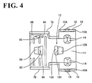
- the terminal 1 is formed e.g. by bending a press-cut workpiece of an electrically conductive plate material or metal plate, and is to be mounted on the stripped end of the coaxial cable 2.
- the terminal 1 is substantially symmetrically formed with respect to the longitudinal axis of the coaxial cable 2, and is provided at its rear side with a barrel portion 7 to be crimped or folded into connection with or crimped or substantially folded onto the folded section 5A of the braided wire 5.
- the barrel portion 7 is comprised of a pair of transversely arranged fastening pieces 7A, 7B, which project at an angle different from 0° or 180°, preferably substantially normal with respect to a longitudinal direction of the terminal 1 or preferably downward while being spaced apart from each other.
- a biting portion 8 projects inward of the barrel portion 7 in the middle of the base ends of the fastening pieces 7A, 7B.
- the biting portion 8 is provided with a transversely extending slit or cut 8A and a slanted surface 8B in the form of an isosceles triangle which is embossed behind the slit 8A to bulge out inwardly, the front edge of the slanted surface 8B serving as a locking edge 8C.
- the locking edge 8C restricts a backward displacement of the coaxial cable 2 since it faces forward.
- the right fastening piece 7A the lower fastening piece in FIG.
- biting portion 9 is formed with a biting portion 9 similar to the above-mentioned biting portion 8. Specifically, a cut 9A is formed at a front side of the biting portion 9, and a portion behind the cut 9A is embossed to bulge out inwardly of the barrel portion 7 so as to serve as a slanted surface 9B and the front edge of the slanted surfaced 9B serves as a locking edge 9C.
- the barrel portion 7 is crimped into connection with the coaxial cable 2
- the right fastening piece 7A is crimped or folded first.
- the both biting portions 8 and 9 hold the coaxial cable 2 in positions opposite to each other with respect to the core 3 of the coaxial cable 2.
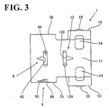
- a cover portion 11 substantially continuous with the barrel portion 7 is provided.
- the cover portion 11 substantially covers portions of the inner insulation coating 4 and the core 3 preferably without being held in contact therewith when the terminal 1 is mounted on the coaxial cable 2.
- a positioning portion 12 is provided at a boundary (a position more toward the front than the center of the terminal 1) of the cover portion 11 and the barrel portion 7.
- the positioning portion 12 is comprised of a slit 12A extending at an angle different from 0° or 180°, preferably substantially normal to a longitudinal direction of the terminal 1 or preferably substantially transversely of the terminal 1, a slanted surface 12B formed by embossing a portion before the slit 12A to bulge out inwardly and having a shape of an isosceles triangle, and a locking edge 12C which is a rear edge of the slanted surface 12B.
- This positioning portion 12 is shaped such that the locking edge 12C is substantially opposed to the locking edge 8C of the biting portion 8 of the barrel portion 7 (see in combination with FIG. 6 ).
- a projecting height or distance D of the positioning portion 12 is longer or greater than a projecting height or distance E of the biting portion 9.
- the biting portion 8 and the positioning portion 12 are preferably oriented substantially opposed to or facing each other, i.e. the biting portion 8 and the positioning portion 12 are embossed or oriented in directions such that the locking edge 8C is arranged after the slanted surface 8B in an insertion direction of the cable 2 whereas the locking edge 12C is arranged before the slanted surface 12B in the insertion direction.
- a pair of leg portions 10 integrally or unitarily extend from the substantially opposite lateral edges of the cover portion 11.
- the leg portions 10 are insertable into mount holes 16 of a printed circuit board 13 to secure the terminal 1 to the printed circuit board 13.
- contacts 19, 20 are provided on the printed circuit board 13 near the edges of the mount holes 16 of the printed circuit board 13 and in a position corresponding to where the core 3 is welded, and are connected with unillustrated circuits.
- a pair of stepped portions 10A are formed in positions of each leg portion 10 near its middle position with respect to its height direction to narrow a width of the leg portion 10 along forward/backward directions from the front and rear sides.
- the stepped portions 10A are or can be brought substantially into contact with the upper surface of the printed circuit board 13 to position the terminal 1.
- Each leg portion 10 is formed with a vertically extending embossed portion 15 below the stepped portions 10A in order to strengthen the leg portion 10 and preferably to lock the leg portion 10 in the corresponding mount hole 16 when the terminal 1 is mounted on the printed circuit board 13.
- a pair of embossed portions 14 are formed at boundaries of the cover portion 11 and the leg portions 10 to strengthen the plate material.
- a heat shrinkable tubing 18 is fitted on the coaxial cable 2 in advance and moved away from the stripped end. Then, as shown in FIG. 7 , the stripped end is brought closer to the rear side of the barrel portion 7 of the terminal 1 while the coaxial cable 2 and the terminal 1 are so supported as to be aligned substantially straight.
- the terminal 1 can be automatically positioned on the coaxial cable 2 with respect to its longitudinal direction.
- the locking edge 12C of the positioning portion 12 projects higher than the locking edge 8C of the biting portion 8, the coaxial cable 2 can be smoothly inserted without being interfered by the biting portion 8.
- the barrel portion 7 is crimped into connection with the coaxial cable 2.
- the right fastening piece 7A is crimped into connection with the outer insulation coating 6 while surrounding the folded section 5A of the braided wire 5, and then the fastening piece 7B is so crimped as to surround the right fastening piece 7A.
- the cover portion 11 covers the core 3 without being held in contact therewith.
- the leg portions 10 of the terminal 1 are mounted into the mount holes 16 of the printed circuit board 13, and the leading ends of the leg portions 10 are connected to the contact 19 e.g. by being soldered, resistance welded or by ultrasonic welding or the like connection at the underside of the printed circuit board 13. It should be noted that the core 3 is soldered after being bent to reach the contact 20 of the printed circuit board 13.
- the positioning portion 12 comes into engagement with a front end 6A of the outer insulation coating 6 of the coaxial cable 2 when the terminal 1 is mounted on the coaxial cable 2, thereby positioning the terminal 1 on the coaxial cable 2 with respect to the longitudinal direction of the coaxial cable 2, and the barrel portion 7 is crimped into connection with the folded section 5A in this state. Accordingly, the terminal 1 can be stably mounted in the predetermined position of the coaxial cable 2.
- the terminal 1 is stably mounted and the core 3 is substantially covered by the cover portion 11 over a predetermined length, with the result that an electrical capacity between the terminal 1 and the core 3 is stabilized to thereby provide stable high frequency characteristics.
- terminal 1 can be easily mounted on the printed circuit board 13 by providing the cover portion 11 with the leg portions 10.
- FIGS. 10 to 12 Another embodiment is described with reference to FIGS. 10 to 12 . It should be noted that no description is given on the same or similar construction as the foregoing embodiment by identifying it by the same or similar reference numerals.
- a positioning portion 30 is formed with a C-shaped cut 30A (in FIG. 10 , only a base portion 30B at the front end of the positioning portion 30 is connected with the cover portion 11, and the remaining three sides are spaced from the cover portion 11 by the cut 30A), and an inner side of the cut 30A is bent inwardly of the terminal 1.
- the positioning portion 30 is bent to a position where it is arranged at an angle different from 0° or 180°, preferably substantially perpendicular to the extension of the cover portion 11, so that it can be held in surface-contact with the front end 6A of the outer insulation coating 6 of the coaxial cable 2. Therefore, the coaxial cable 2 can be more accurately positioned.
- the embodiment thus constructed has the same action and effects as the foregoing embodiment.
Landscapes
- Coupling Device And Connection With Printed Circuit (AREA)
- Multi-Conductor Connections (AREA)
Claims (10)
- Elément de connexion (1) pouvant être monté sur un câble (2) constitué d'un revêtement isolant (4), d'une âme (3) se projetant depuis l'extrémité avant du revêtement isolant (4), comprenant :une partie à barillet (7) qui doit être sertie jusque dans la connexion avec une partie (5) du câble (2), etune partie de positionnement (12 ; 30) qui doit être sensiblement maintenue en engagement avec le câble (2) afin de positionner l'élément de connexion (1) sur le câble (2) par rapport à la direction longitudinale du câble (2) avant que la partie à barillet (7) soit sertie jusque dans la connexion avec la partie (5) du câble (2),caractérisé par
une partie de recouvrement (11) qui s'étend sensiblement en continu depuis la partie à barillet (7) de manière à recouvrir sensiblement l'âme dégagée (3) sans être maintenue en contact avec celle-ci lorsque l'élément de connexion (1) est monté sur le câble (2). - Utilisation d'un élément de connexion conformément à la revendication 1 par le montage de l'élément de connexion (1) sur un câble coaxial (2) constitué d'un revêtement isolant intérieur (4), d'une âme (3) se projetant depuis l'extrémité avant du revêtement isolant intérieur (4), d'un revêtement isolant extérieur (6), et d'une couche de blindage (5) qui entoure le revêtement isolant intérieur (4) et qui est rabattue au moins en partie de manière à être amenée sensiblement en contact fermé avec la surface extérieure du revêtement isolant extérieur (6),
opération pendant laquelle la partie à barillet (7) est sertie jusque dans la connexion avec un tronçon bordé (5A) de la couche de blindage (5) du câble coaxial (2). - Elément de connexion conformément à la revendication 1, dans lequel la partie de recouvrement (11) est formée en un seul tenant ou unitairement avec une ou plusieurs parties en forme de branche (10) pour le montage de l'élément de connexion (1) sur une carte de circuit imprimé (13).
- Elément de connexion conformément à la revendication 3, dans lequel les parties en forme de branche (10) sont prévues avec une ou plusieurs parties en relief (14 ; 15) afin de renforcer les parties en forme de branche (10) et/ou de bloquer les parties en forme de branche (10) dans des trous de montage correspondants (16) de la carte de circuit imprimé (13).
- Elément de connexion conformément à l'une ou l'autre des revendications 3 et 4, dans lequel les parties en forme de branche (10) sont prévues avec des parties étagées (10A) afin de venir en engagement avec la carte de circuit imprimé (13) suite à l'insertion des parties en forme de branche (10) jusque dans des trous de montage (16) de la carte de circuit imprimé (13).
- Elément de connexion conformément à l'une ou plus des revendications précédentes, dans lequel la partie à barillet (7) est formée avec au moins une partie de pénétration (8 ; 9) qui se projette vers l'intérieur afin de pénétrer dans une partie du câble (2), de préférence dans la couche de blindage (5) de celui-ci.
- Elément de connexion conformément à la revendication 6, dans lequel une hauteur de projection (E) de la partie de pénétration (8 ; 9) est plus courte que celle (D) de la partie de positionnement (12 ; 30) de peur que la partie de pénétration (8 ; 9) puisse entraver l'insertion du câble (2) jusque dans l'élément de connexion (1).
- Elément de connexion conformément à l'une ou l'autre des revendications 6 et 7, dans lequel la partie de pénétration (8) et la partie de positionnement (12 ; 30) sont agencées sensiblement à l'opposé l'une de l'autre le long d'une direction de pose du câble (2).
- Elément de connexion conformément à l'une ou plus des revendications 1 ou 3 à 8, dans lequel l'élément de connexion (1) est construit de telle sorte que le câble (2) puisse être inséré dans l'élément de connexion (1) jusqu'à la partie de recouvrement (11) depuis un côté de la partie à barillet (7) le long de sa direction longitudinale, et dans lequel la partie de positionnement (12 ; 30) est formée en effectuant une coupe (12A ; 30A) dans la partie de recouvrement (11) et en pliant la partie coupée, et peut être engagée avec une partie du câble (2), de préférence avec l'extrémité avant du revêtement isolant extérieur (6) qui est une position de départ du tronçon bordé (5A) de la couche de blindage (5).
- Procédé pour le montage d'un élément de connexion (1) conformément à l'une ou plus des revendications précédentes sur un câble (2) constitué d'un revêtement isolant (4), d'une âme (3) se projetant depuis l'extrémité avant du revêtement isolant (4), comprenant les étapes consistant à :positionner l'élément de connexion (1) sur le câble (2) par rapport à la direction longitudinale du câble (2) en amenant une partie de positionnement (12 ; 30) sensiblement en engagement avec le câble (2), etsertir une partie à barillet (7) jusque dans la connexion avec une partie (5) du câble (2),caractérisé par
le fait de prévoir une partie de recouvrement (11) qui s'étend sensiblement en continu depuis la partie à barillet (7) de manière à recouvrir sensiblement l'âme dégagée (3) sans être maintenue en contact avec celle-ci.
Applications Claiming Priority (2)
| Application Number | Priority Date | Filing Date | Title |
|---|---|---|---|
| JP12896399 | 1999-05-10 | ||
| JP12896399A JP3419709B2 (ja) | 1999-05-10 | 1999-05-10 | 同軸ケーブル用端子 |
Publications (2)
| Publication Number | Publication Date |
|---|---|
| EP1052730A1 EP1052730A1 (fr) | 2000-11-15 |
| EP1052730B1 true EP1052730B1 (fr) | 2009-07-22 |
Family
ID=14997754
Family Applications (1)
| Application Number | Title | Priority Date | Filing Date |
|---|---|---|---|
| EP00109813A Expired - Lifetime EP1052730B1 (fr) | 1999-05-10 | 2000-05-09 | Elément de connexion électrique pour un câble et méthode de montage |
Country Status (5)
| Country | Link |
|---|---|
| US (1) | US6372990B1 (fr) |
| EP (1) | EP1052730B1 (fr) |
| JP (1) | JP3419709B2 (fr) |
| CN (1) | CN1124666C (fr) |
| DE (1) | DE60042574D1 (fr) |
Families Citing this family (22)
| Publication number | Priority date | Publication date | Assignee | Title |
|---|---|---|---|---|
| JP2005317298A (ja) | 2004-04-28 | 2005-11-10 | Hirose Electric Co Ltd | 同軸ケーブル用端子と、この同軸ケーブル用端子の取付構造及び取付方法 |
| US7207806B2 (en) * | 2004-08-06 | 2007-04-24 | Broadcom Corporation | Low cost coaxial cable connection for wireless antennas |
| US7665890B2 (en) | 2006-06-22 | 2010-02-23 | Watlow Electric Manufacturing Company | Temperature sensor assembly and method of manufacturing thereof |
| US7722362B2 (en) * | 2006-06-22 | 2010-05-25 | Watlow Electric Manufacturing Company | Sensor adaptor circuit housing incapsulating connection of an input connector with a wire |
| JP4965226B2 (ja) * | 2006-06-23 | 2012-07-04 | 株式会社オートネットワーク技術研究所 | 外導体端子 |
| US20110011638A1 (en) * | 2009-07-16 | 2011-01-20 | Paul Gemme | Shielding tape with edge indicator |
| US9728304B2 (en) | 2009-07-16 | 2017-08-08 | Pct International, Inc. | Shielding tape with multiple foil layers |
| US8882520B2 (en) | 2010-05-21 | 2014-11-11 | Pct International, Inc. | Connector with a locking mechanism and a movable collet |
| US8579658B2 (en) | 2010-08-20 | 2013-11-12 | Timothy L. Youtsey | Coaxial cable connectors with washers for preventing separation of mated connectors |
| TWI558007B (zh) * | 2011-09-27 | 2016-11-11 | 緯創資通股份有限公司 | 用來連接同軸線纜與電路板之連接器及其相關之傳輸線與組裝方法 |
| EP2592914B1 (fr) * | 2011-11-14 | 2015-05-06 | Continental Automotive GmbH | Elément de serrage |
| US9028276B2 (en) | 2011-12-06 | 2015-05-12 | Pct International, Inc. | Coaxial cable continuity device |
| US9004937B2 (en) * | 2012-08-30 | 2015-04-14 | Zierick Manufacturing Corporation | Surface mount/through-hole crimp piercing zipcord connector |
| CN104065021B (zh) * | 2014-04-23 | 2016-08-17 | 李超 | 一种电缆假接头 |
| EP3089272A1 (fr) * | 2015-04-29 | 2016-11-02 | AGC Glass Europe | Panneau de vitrage présentant un connecteur électroconducteur |
| WO2019032366A1 (fr) * | 2017-08-07 | 2019-02-14 | Commscope Technologies Llc | Ensembles blocs de connecteur de câble destinés à des antennes de station de base |
| CN109411967B (zh) * | 2017-08-17 | 2025-02-18 | 春源科技(深圳)有限公司 | 高频rf连接构件及其高频rf跳线与板端连接器 |
| CN109273958B (zh) * | 2018-09-13 | 2020-10-02 | 苏州热工研究院有限公司 | 一种用于核级同轴电缆接头制作的工具 |
| JP7143207B2 (ja) * | 2018-12-21 | 2022-09-28 | ヒロセ電機株式会社 | 対の圧着片を有するハウジングを備えた同軸ケーブルコネクタ |
| EP3788958A1 (fr) * | 2019-09-09 | 2021-03-10 | Heraeus Deutschland GmbH & Co KG | Contact électrique entre des fils revêtus de polymère électriquement conducteurs et des substrats électriquement conducteurs utilisant une liaison de fils |
| JP6869570B1 (ja) * | 2019-12-26 | 2021-05-12 | 株式会社トライサウンド | 電子撥弦楽器用プラグ及び電子撥弦楽器用プラグ付きケーブル |
| JP7453792B2 (ja) | 2020-01-16 | 2024-03-21 | 日本航空電子工業株式会社 | 固定具、固定方法、ケーブル組立体及び構造体 |
Family Cites Families (19)
| Publication number | Priority date | Publication date | Assignee | Title |
|---|---|---|---|---|
| US3383457A (en) | 1966-04-05 | 1968-05-14 | Amp Inc | Connector means for connecting coaxial cable to a printed circuit board |
| US3670293A (en) * | 1970-08-20 | 1972-06-13 | Amp Inc | Shielded wire connectors |
| BE794947A (fr) * | 1972-02-02 | 1973-08-02 | Raychem Corp | Procede et dispositif de connexion |
| US4178054A (en) | 1977-08-22 | 1979-12-11 | Amp Incorporated | Plug termination for coaxial cable |
| US4269469A (en) * | 1978-04-21 | 1981-05-26 | Souriau & Cie | Contact terminal connector |
| US5059140A (en) * | 1984-01-16 | 1991-10-22 | Stewart Stamping Corporation | Shielded plug and jack connector |
| GB8726934D0 (en) * | 1987-11-18 | 1987-12-23 | Amp Gmbh | Electrical terminal assembly |
| JP2516089B2 (ja) * | 1990-06-22 | 1996-07-10 | ヒロセ電機株式会社 | コネクタの結線構造とその方法 |
| JPH0727572Y2 (ja) * | 1990-09-11 | 1995-06-21 | ヒロセ電機株式会社 | 電気コネクタ |
| JPH04214643A (ja) * | 1990-12-12 | 1992-08-05 | Nec Kyushu Ltd | 樹脂封止型半導体装置 |
| JPH05290249A (ja) | 1992-04-06 | 1993-11-05 | Resortmation Eng:Kk | 商品券用バーコード管理システム |
| JP2772322B2 (ja) * | 1993-03-08 | 1998-07-02 | 矢崎総業株式会社 | シールド電線の端末接続構造 |
| JP2899933B2 (ja) * | 1993-03-24 | 1999-06-02 | 日本航空電子工業株式会社 | ケーブル接続コンタクト及びその製造方法、ケーブル接続コンタクトを用いたコネクタ装置 |
| SG43073A1 (en) * | 1993-05-14 | 1997-10-17 | Molex Inc | Shielded electrical connector assembly |
| JPH08186414A (ja) | 1994-12-27 | 1996-07-16 | Tokin Corp | 端子ピン |
| JP3202561B2 (ja) * | 1995-11-17 | 2001-08-27 | 矢崎総業株式会社 | 雄型端子金具 |
| JP3851711B2 (ja) * | 1997-07-22 | 2006-11-29 | 株式会社オートネットワーク技術研究所 | シールドコネクタ |
| DE29721752U1 (de) * | 1997-12-09 | 1998-02-12 | Siemens AG, 80333 München | Crimpkontakt für Stecksysteme |
| US6175080B1 (en) * | 1999-04-28 | 2001-01-16 | Tektronix, Inc. | Strain relief, pull-strength termination with controlled impedance for an electrical cable |
-
1999
- 1999-05-10 JP JP12896399A patent/JP3419709B2/ja not_active Expired - Fee Related
-
2000
- 2000-05-09 US US09/567,692 patent/US6372990B1/en not_active Expired - Lifetime
- 2000-05-09 DE DE60042574T patent/DE60042574D1/de not_active Expired - Lifetime
- 2000-05-09 EP EP00109813A patent/EP1052730B1/fr not_active Expired - Lifetime
- 2000-05-10 CN CN00107378A patent/CN1124666C/zh not_active Expired - Fee Related
Also Published As
| Publication number | Publication date |
|---|---|
| CN1124666C (zh) | 2003-10-15 |
| CN1273444A (zh) | 2000-11-15 |
| DE60042574D1 (de) | 2009-09-03 |
| US6372990B1 (en) | 2002-04-16 |
| JP3419709B2 (ja) | 2003-06-23 |
| EP1052730A1 (fr) | 2000-11-15 |
| JP2000323213A (ja) | 2000-11-24 |
Similar Documents
| Publication | Publication Date | Title |
|---|---|---|
| EP1052730B1 (fr) | Elément de connexion électrique pour un câble et méthode de montage | |
| KR100256927B1 (ko) | 고속 케이블의 차폐부 접속 시스템 | |
| JP3015942B2 (ja) | 高速伝送線のシールド終端装置 | |
| US5711686A (en) | System for terminating the shield of a high speed cable | |
| CA1060966A (fr) | Borne enfichable | |
| GB2267187A (en) | Mass termination of multi-coaxial cable | |
| EP0793307A2 (fr) | Système de terminaison d'écran d'un câble à grande vitesse | |
| US8602831B2 (en) | Terminal having hanging parts from the sides and one end | |
| EP0542075B1 (fr) | Procédé pour terminer un connecteur électrique miniature coaxial et un connecteur terminé selon le procédé | |
| US4921439A (en) | Center wire trap terminal and connector | |
| KR100282632B1 (ko) | 고속 케이블의 차폐부를 종단 접속하기 위한 시스템 | |
| EP1133003B1 (fr) | Connecteur mâle | |
| US5358426A (en) | Connector assembly for discrete wires of a shielded cable | |
| US6483035B2 (en) | Protecting configuration for flat cables | |
| US5272807A (en) | Method of assembling a connector to electrical conductors | |
| US7402073B2 (en) | Cable connector and method of connecting a cable with a cable connector | |
| JP3425634B2 (ja) | 高速ケーブル用のシールド終端機構を備えた電気コネクタ | |
| KR101521386B1 (ko) | 케이블 접속 방법 | |
| US5186656A (en) | Miniature coaxial electrical connector | |
| EP0570832B1 (fr) | Assemblage de boîtier de connecteur pour des fils discrets | |
| US6325681B1 (en) | Cable connector and contacts for cable connector | |
| US7052324B2 (en) | Plug connector having a damping element | |
| TWM680631U (zh) | 用於將扁平連接對象物連接於複數個同軸電纜的轉接連接器 |
Legal Events
| Date | Code | Title | Description |
|---|---|---|---|
| PUAI | Public reference made under article 153(3) epc to a published international application that has entered the european phase |
Free format text: ORIGINAL CODE: 0009012 |
|
| 17P | Request for examination filed |
Effective date: 20000531 |
|
| AK | Designated contracting states |
Kind code of ref document: A1 Designated state(s): DE FR GB IT |
|
| AX | Request for extension of the european patent |
Free format text: AL;LT;LV;MK;RO;SI |
|
| AKX | Designation fees paid |
Free format text: DE FR GB IT |
|
| 17Q | First examination report despatched |
Effective date: 20041011 |
|
| 17Q | First examination report despatched |
Effective date: 20041011 |
|
| GRAP | Despatch of communication of intention to grant a patent |
Free format text: ORIGINAL CODE: EPIDOSNIGR1 |
|
| RIN1 | Information on inventor provided before grant (corrected) |
Inventor name: SAITO, MASASHI, Inventor name: AOYAMA, MASAHIKO, Inventor name: KOIDE, TAKASHI, |
|
| GRAS | Grant fee paid |
Free format text: ORIGINAL CODE: EPIDOSNIGR3 |
|
| GRAA | (expected) grant |
Free format text: ORIGINAL CODE: 0009210 |
|
| AK | Designated contracting states |
Kind code of ref document: B1 Designated state(s): DE FR GB IT |
|
| REG | Reference to a national code |
Ref country code: GB Ref legal event code: FG4D |
|
| REF | Corresponds to: |
Ref document number: 60042574 Country of ref document: DE Date of ref document: 20090903 Kind code of ref document: P |
|
| PLBE | No opposition filed within time limit |
Free format text: ORIGINAL CODE: 0009261 |
|
| STAA | Information on the status of an ep patent application or granted ep patent |
Free format text: STATUS: NO OPPOSITION FILED WITHIN TIME LIMIT |
|
| 26N | No opposition filed |
Effective date: 20100423 |
|
| PGFP | Annual fee paid to national office [announced via postgrant information from national office to epo] |
Ref country code: DE Payment date: 20130515 Year of fee payment: 14 Ref country code: GB Payment date: 20130508 Year of fee payment: 14 |
|
| PGFP | Annual fee paid to national office [announced via postgrant information from national office to epo] |
Ref country code: IT Payment date: 20130423 Year of fee payment: 14 Ref country code: FR Payment date: 20130531 Year of fee payment: 14 |
|
| REG | Reference to a national code |
Ref country code: DE Ref legal event code: R119 Ref document number: 60042574 Country of ref document: DE |
|
| GBPC | Gb: european patent ceased through non-payment of renewal fee |
Effective date: 20140509 |
|
| REG | Reference to a national code |
Ref country code: FR Ref legal event code: ST Effective date: 20150130 |
|
| REG | Reference to a national code |
Ref country code: DE Ref legal event code: R119 Ref document number: 60042574 Country of ref document: DE Effective date: 20141202 |
|
| PG25 | Lapsed in a contracting state [announced via postgrant information from national office to epo] |
Ref country code: IT Free format text: LAPSE BECAUSE OF NON-PAYMENT OF DUE FEES Effective date: 20140509 Ref country code: DE Free format text: LAPSE BECAUSE OF NON-PAYMENT OF DUE FEES Effective date: 20141202 |
|
| PG25 | Lapsed in a contracting state [announced via postgrant information from national office to epo] |
Ref country code: GB Free format text: LAPSE BECAUSE OF NON-PAYMENT OF DUE FEES Effective date: 20140509 Ref country code: FR Free format text: LAPSE BECAUSE OF NON-PAYMENT OF DUE FEES Effective date: 20140602 |