EP1052738A2 - Connecteur électrique blindé ayant un ressort de contact de masse - Google Patents
Connecteur électrique blindé ayant un ressort de contact de masse Download PDFInfo
- Publication number
- EP1052738A2 EP1052738A2 EP00109753A EP00109753A EP1052738A2 EP 1052738 A2 EP1052738 A2 EP 1052738A2 EP 00109753 A EP00109753 A EP 00109753A EP 00109753 A EP00109753 A EP 00109753A EP 1052738 A2 EP1052738 A2 EP 1052738A2
- Authority
- EP
- European Patent Office
- Prior art keywords
- shield
- connector
- plug
- body portion
- elbow
- Prior art date
- Legal status (The legal status is an assumption and is not a legal conclusion. Google has not performed a legal analysis and makes no representation as to the accuracy of the status listed.)
- Withdrawn
Links
- 239000004020 conductor Substances 0.000 claims description 3
- 238000003780 insertion Methods 0.000 description 11
- 230000037431 insertion Effects 0.000 description 11
- 230000013011 mating Effects 0.000 description 11
- 238000004519 manufacturing process Methods 0.000 description 7
- 238000000034 method Methods 0.000 description 3
- 238000012986 modification Methods 0.000 description 3
- 230000004048 modification Effects 0.000 description 3
- 238000006467 substitution reaction Methods 0.000 description 3
- 230000000712 assembly Effects 0.000 description 2
- 238000000429 assembly Methods 0.000 description 2
- 238000005452 bending Methods 0.000 description 2
- 230000000694 effects Effects 0.000 description 2
- 238000004049 embossing Methods 0.000 description 2
- 239000002184 metal Substances 0.000 description 2
- 238000005476 soldering Methods 0.000 description 2
- 230000001154 acute effect Effects 0.000 description 1
- 230000001747 exhibiting effect Effects 0.000 description 1
Images


Classifications
-
- H—ELECTRICITY
- H01—ELECTRIC ELEMENTS
- H01R—ELECTRICALLY-CONDUCTIVE CONNECTIONS; STRUCTURAL ASSOCIATIONS OF A PLURALITY OF MUTUALLY-INSULATED ELECTRICAL CONNECTING ELEMENTS; COUPLING DEVICES; CURRENT COLLECTORS
- H01R13/00—Details of coupling devices of the kinds covered by groups H01R12/70 or H01R24/00 - H01R33/00
- H01R13/648—Protective earth or shield arrangements on coupling devices, e.g. anti-static shielding
- H01R13/652—Protective earth or shield arrangements on coupling devices, e.g. anti-static shielding with earth pin, blade or socket
-
- H—ELECTRICITY
- H01—ELECTRIC ELEMENTS
- H01R—ELECTRICALLY-CONDUCTIVE CONNECTIONS; STRUCTURAL ASSOCIATIONS OF A PLURALITY OF MUTUALLY-INSULATED ELECTRICAL CONNECTING ELEMENTS; COUPLING DEVICES; CURRENT COLLECTORS
- H01R13/00—Details of coupling devices of the kinds covered by groups H01R12/70 or H01R24/00 - H01R33/00
- H01R13/648—Protective earth or shield arrangements on coupling devices, e.g. anti-static shielding
- H01R13/658—High frequency shielding arrangements, e.g. against EMI [Electro-Magnetic Interference] or EMP [Electro-Magnetic Pulse]
- H01R13/6581—Shield structure
- H01R13/6582—Shield structure with resilient means for engaging mating connector
Definitions
- the present invention generally relates to the art of electrical connectors and particularly to a connector having a shield that engages in grounding contact with a cooperatively mating connector.
- known electrical connectors have included an electromagnetic shield. It is also known to establish contact between the electromagnetic shield and a cooperatively mated plug that is inserted into the connector. This is intended to provide an enhanced grounding and shielding of the connector.
- the spring wit a spring that biases against the inserted mating connector.
- the spring is sometimes referred to in the art as a detent or a positive lock. It is known to form the spring and shield integrally from a metal sheet. In particular, the spring is defined by a cut in the shield, then formed by bending. The spring may be designed to exhibit desired forces and strength characteristics by varying the thickness (see Japanese Patent Laid-Open Publication No. Hei 10-32043).
- a connector cable assembly is known for a USB (Universal Serial Bus) or the like.
- Such an assembly includes two connectors, one on each end.
- the shields of the connectors mounted to the cable have previously been manufactured to have respectively different shapes. Because the shapes of the respective shields and corresponding mating connectors are completely different, such connector cable assemblies have high manufacturing costs.
- an electrical connector is provided of the type adapted to receive a mated plug.
- the connector includes an insulative housing. A plurality of conductive terminals are disposed in the housing.
- the connector also includes a conductive shield at least partially covering the housing. The shield has a cavity within which the mated plug is received.
- the connector includes a ground spring including an elongate, resilient body portion and a ground contact portion.
- the body portion of the ground spring has a mounted end integrally connected to the shield and a ground contact end distally opposite the mounted end.
- the ground contact end is shaped to slidably engage against the mated plug.
- the elongate body portion has at least one generally right-angled elbow at a location intermediately between the mounted end and wound contact ends.
- the shield includes at least a first panel and a second panel oriented at a generally right angle relative to each other.
- the resilient body portion is generally L-shaped, having a first section between the mounted end and the elbow and a second section between the elbow and the contact end, each of the first and second sections being generally planar.
- the first and second sections are generally disposed in a common plane, such that the L-shaped body portion may reside coincident with the first planar shield panel.
- the first and second sections are disposed in respective planes generally perpendicular to each other so that the elbow of the L-shaped body portion lies generally coincident with a corner of the first and second shield panels.
- the ground spring and the shield are unitary.
- the ground spring is defined by a cut in the shield.
- An advantage of the present invention is to provide an improved connector.
- Another advantage of the present invention is to provide a connector including a ground spring having substantial length in a compact space.
- the L-shaped body portion provides the ground spring with substantial length, allowing miniaturization of the connector without sacrificing ground spring performance.
- a further advantage of the present invention is to provide a connector wherein the ground spring has suitable flexibility and deflection characteristics.
- the shield is configured to include a first panel that extends in an insertion direction of the mated plug, the second panel extends in a direction orthogonal to the insertion direction, and wherein a first section of the body portion of the ground spring lies in the second panel, and the ground contact end lies in the first panel.
- the shield is configured to include a first panel extending in the insertion direction and the second panel has a surface extending in a direction orthogonal to the first panel, the ground spring having a mounted end joined to the first panel and an opposite ground contact end in the second panel.
- the spring member is formed to extend over the two panels of the shield, thereby to ensure a sufficient span of the ground spring.
- a connector cable assembly is provided. More particularly, the assembly cable includes a cable having a first end and a second end, a first connector being connected to the first end, and a second connector being connected to the second end.
- each of the plugs has a shield including key portion, such as a bump or projection, for mating and connecting with a correspondingly-keyed mated plug. This permits the connector to be mated with only with a corresponding counterpart plug.
- the key portion or projection can be formed integrally with the shield.
- the connector device can be advantageously manufactured at a low cost.
- the connectors at opposite ends of the serial bus cable are provided with respectively different key portions such that the mated plug associated with one cannot be matably received by the other.
- Such an embodiment advantageously prevents inadvertent misconnections.
- the shield and the key portion provided thereon can be manufactured together by a simple press working. Furthermore, the position of the projection provided on the surface of the shield can be easily changed by merely changing a position of a die used for the drawing process, specifically for embossing or a half-knock process. In other words, two kinds of connectors can be manufactured by one press working facility, thereby to provide a connector device which can be manufactured at a low cost.
- An advantage of the present invention is to provide an improved electrical connector.
- Another advantage of the present invention is to provide an electrical connector that has improved grounding contact.
- a further advantage of the present invention is to provide an electrical connector that has an improved grounding spring.
- a related advantage is to provide an electrical connector having a reliable grounding spring contact.
- the shield includes at least a first panel and a second panel oriented at a generally right angle relative to each other.
- Yet another advantage is to provide an electrical connector having a reduced size.
- a still further advantage of the present invention is to provide an electrical connector that can be manufactured economically with reduced costs.
- Yet another advantage of the present invention is to provide a connector having a ground spring which can be easily designed to have a wide range of spring characteristics.
- a still further advantage is to provide a connector that establishes and maintains a reliable a ground contact with a mated plug received therein.
- FIG. 1 a conventional electrical connector 20 is illustrated in FIG. 1.
- the conventional connector 20 has an insulative housing 22 having a receptacle opening 24 at a mating side for receiving a mated plug connector (not shown) in an insertion direction.
- a plurality of conductive terminals 26 are disposed in the housing 22 for contacting corresponding conductors on the mated plug connector.
- the connector 20 further includes a conductive shield 28 that covers the housing 22. Integral with the shield 28 is a substantially straight ground spring 30 that is oriented generally along the insertion direction.
- the ground spring 30 has a contact portion 31 shaped to conductively contact against the mated plug connector upon the insertion thereof into the receptacle opening 24 to establish better shielding.
- miniaturization of the connector 20 results in lessened dimensions of the ground spring 30. This makes it difficult to design the ground spring 30 to yield desired characteristics.
- the cable assembly 34 includes a flexible, insulated cable 36 containing wiring.
- a first connector 38 is mounted at a first end of the cable 36, and a second connector 40 is mounted to a second end of the cable 36.
- Each of the connectors 38, 40 is adapted for mating with a corresponding mated connector (not shown).
- Each of the connectors 38, 40 includes a respective conductive shield 42, 44 for engaging the corresponding mated connector.
- the connectors 38, 40 are provided with respectively different shapes.
- the first connector 38 has a series A type configuration, the shield 42 having a narrow, rectangular shape around a plurality of conductive terminals 46 arranged in a row.
- the second connector has a series B type configuration, the shield 44 having a hexagonal shape surrounding a plurality of terminals 48 arranged in a rectangular pattern.
- the first connector 38 and second connector 40 could not be interchanged, but can only mate with a correspondingly shaped mating connector.
- completely separate tooling is required to manufacture each of the different first and second connectors 38, 40. This can be costly and inefficient.
- FIGS. 3-13 various connector shields are illustrated constructed in accordance with teachings of the present invention.
- a shield 50 according a first embodiment is illustrated in FIGS. 3-6.
- the shield 50 is adapted to at least partially cover an insulating housing for receiving a mated plug connector.
- the shield 50 generally includes an upper panel 52, a pair of side panels 54, 56 and a rear panel 58.
- the rear panel 58 does not extend downwardly as far as the side panels 54, 56 to allow terminal tails (see 26 in Figure 1) to extend rearwardly of the shield 50.
- Each of the side panels 54, 56 includes a pair of mounting tabs 60 for securing the shield to a surface, such as a circuit board (not shown).
- the mounting tabs 60 may be mounted by soldering, providing a grounded contact for the shield 50 to the circuit board.
- a front of the shield opens into a cavity 51 (FIG. 5) for containing a housing and terminals (not shown) of a connector within the panels 52, 54, 56.
- the shield 50 may be manufactured in a unitary manner by stamping and bending a metal plate.
- a plug connector (not shown) is inserted into the cavity 51 of the connector to effect mating.
- the shield For establishing grounding contact with the mated plug connect or upon insertion of the plug, and for securing the plug in an inserted position, the shield includes a ground spring 62.
- the ground spring 62 is unitary with the shield 50, being formed by a cut 64 in the upper panel 52 and rear panel 58.
- the ground spring 62 includes an elongate, resilient body portion 66 and a ground contact portion 68 (FIGS. 3 and 6).
- the body portion 66 has a mounted end 70 (FIGS. 4 and 6) integrally connected to the rear 58 panel of the shield 50.
- the ground contact portion 68 is distal from the mounted end 70.
- the ground contact portion 68 is shaped to engage against the mated plug. As illustrated in FIG. 5, the ground contact portion 68 has a contact apex 72 that projects downwardly to form a point of contact against the mated plug. Also, the ground contact portion 68 has an upwardly-ramped tip for slidably engaging the mated plug connector during insertion, thus deflecting the ground spring 62 into biased contact against the plug at the contact apex 72.
- the elongate body portion 66 has at least one generally angled elbow 74 at a location intermediately between the mounted end 70 and the ground contact portion 68, as illustrated in FIGS. 5 and 6.
- the resilient body portion 66 has a first section 76 between the mounted end 70 and the elbow 74 and a second section 78 between the elbow 74 and the contact portion 68.
- the second section 78 is preferably oriented along a direction in which the mated plug is inserted.
- the first and second sections 76, 78 are disposed in respectively different planes.
- the first section 76 normally lies in a plane common with the rear panel 58
- the second section 78 lies in a plane generally common with the upper panel 52.
- the second section 78 angles slightly inwardly from the plane of the upper panel 52, positioning the ground contact portion 68 within the cavity 51.
- the second section 78 is at an angle ⁇ 1 relative to the rear panel 58 which is less than an angle 2 between the rear panel 58 and the upper panel 52.
- the angle ⁇ 1 is an acute angle.
- the resilient body portion 66 of the ground spring 62 deflects (both the first section 76 and the second section 78). The spring 62 thereby exerts a spring bias against the mated plug connector.
- a connector shield 150 is provided as illustrated in FIGS. 7-10.
- the shield 150 is adapted to at least partially cover an insulating housing for receiving a mated plug connector.
- the shield 150 generally includes an upper panel 152, a pair of side panels 154, 156 and a rear panel 158.
- the rear panel 158 does not extend downwardly as far as the side panels 154, 156 to allow terminal tails (see 26 in Figure 1) to extend rearwardly of the shield 150.
- Each of the side panels 154, 156 includes a pair of mounting tabs 160 for securing the shield to a surface, such as a circuit board (not shown).
- the mounting tabs 160 may be mounted by soldering, providing a grounded contact for the shield 150 for the circuit board.
- a front of the shield 150 opens into a cavity 151 (FIG. 10) for containing a housing and terminals (not shown) of a connector within the panels 152, 154, 156.
- a plug connector (not shown) is inserted into the cavity 151 to effect connector mating.
- the shield 150 For establishing grounding contact with the mated plug connect or upon insertion of the plug, and for securing the plug in an inserted position, the shield 150 includes a ground spring 162.
- the ground spring 162 is unitary with the shield 150, being formed by a cut 164 in the upper panel 152 and side panel 158.
- the ground spring 162 includes an elongate, resilient body portion 166 and a ground contact portion 168 (FIGS. 9 and 10).
- the body portion 166 has a mounted end 170 (FIGS. 7 and 10) integrally connected to the upper panel 152 of the shield 150.
- the ground contact portion 168 is distal from the mounted end 170.
- the ground contact portion 168 is shaped to engage against the mated plug. As illustrated in FIGS. 7 and 10, the ground contact portion 168 has a contact apex 172 that projects inwardly to form a point of contact against the mated plug. Also, the ground contact portion 168 has a ramped tip for slidably engaging the mated plug connector during insertion, thus deflecting the ground spring 162 into biased contact against the plug at the contact apex 172.
- the elongate body portion 166 has a first elbow 174 and a second elbow 175, as illustrated in FIGS. 9 and 10. Each of the elbows 154, 175 is disposed intermediately along the body portion 166 between the mounted end 170 and ground contact portion 168.
- the resilient body portion 166 has a first section 176 between the mounted end 170 and the first elbow 74, a third section 179 between the first elbow 174 and the second elbow 175, and a second section 178 between the second elbow 175 and the contact portion 168.
- the second section 178 is preferably oriented along a direction in which the mated plug is inserted. Also, the second section 178 is angled slightly inwardly. As the contact portion 68 of the ground spring 162 is pushed outwardly, the resilient body portion 166 of the ground spring 162 deflects (both the first section 176 and the second section 178). The spring 162 thereby exerts a spring bias against the mated plug connector.
- the connector cable assembly includes a cable 202 having opposite first and second ends.
- a first plug connector 210a is mounted at the first end of the cable, and a second plug connector 210b is mounted at the second end of the cable.
- the first plug connector 210a is adapted to mate with a first receptacle connector
- the second plug connector 210b is adapted to mate with a second receptacle connector.
- components of the first plug connector 210a are indicated herein with reference numbers containing the letter "a" and components of the second plug connector 210 are indicated with a "b.”
- each of the first and second plug connectors 210a, 210b includes an insulative housing 212a 212b and a plurality of conductive terminals 214a, 214b disposed in the respective housing 212a, 212b.
- the terminals 214a, 214b are terminated to conductors in the cable 202.
- each of the plug connectors 210a 210b includes a respective conductive shield 216a 216b.
- the shield 216a, 216b at least partially covers the housing 212a, 212b of the respective connector 210a 210b.
- each of the connectors 210a, 210b has a respective first side and a second side as bifurcated by an imaginary central line X.
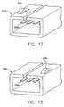
- the shield 216a of the first plug connector 210a includes a keying projection 218a on the first side (shown left in FIGS. 11 and 12) of the shield 216a and in contrast, the shield 216b of the second plug connector 210b includes a keying projection 218b on the second side (shown right in FIGS. 11 and 13) of the connector.
- the projection 218a, 218b may be formed in the respective shield 216a 216b by a drawing process, such as, embossing or half-knock, which is applied from an inner side of the shield.
- the projection is slidably received within a corresponding key groove extending along an insertion direction in the mated receptacle connector.
- the first and second connectors 210a, 210b may be substantially identical except that the projections 218a, 218b are on respectively different sides.
- the connectors 210a and 210b can be manufactured with shared manufacturing tooling and assembly steps, except for the simple forming of the keying projection is performed on the appropriate side.
Landscapes
- Details Of Connecting Devices For Male And Female Coupling (AREA)
Applications Claiming Priority (2)
| Application Number | Priority Date | Filing Date | Title |
|---|---|---|---|
| JP12913399 | 1999-05-10 | ||
| JP11129133A JP2000323233A (ja) | 1999-05-10 | 1999-05-10 | コネクタ装置 |
Publications (2)
| Publication Number | Publication Date |
|---|---|
| EP1052738A2 true EP1052738A2 (fr) | 2000-11-15 |
| EP1052738A3 EP1052738A3 (fr) | 2002-04-24 |
Family
ID=15001932
Family Applications (1)
| Application Number | Title | Priority Date | Filing Date |
|---|---|---|---|
| EP00109753A Withdrawn EP1052738A3 (fr) | 1999-05-10 | 2000-05-09 | Connecteur électrique blindé ayant un ressort de contact de masse |
Country Status (8)
| Country | Link |
|---|---|
| US (1) | US6368154B1 (fr) |
| EP (1) | EP1052738A3 (fr) |
| JP (1) | JP2000323233A (fr) |
| KR (1) | KR100379209B1 (fr) |
| CN (1) | CN100420104C (fr) |
| MY (1) | MY122330A (fr) |
| SG (1) | SG87113A1 (fr) |
| TW (1) | TW454979U (fr) |
Cited By (4)
| Publication number | Priority date | Publication date | Assignee | Title |
|---|---|---|---|---|
| WO2002077905A1 (fr) * | 2001-03-26 | 2002-10-03 | Molex Incorporated | Connecteur de carte blinde comportant des contacts ameliores |
| WO2010061249A1 (fr) * | 2008-11-28 | 2010-06-03 | Fci | Enveloppe de blindage |
| WO2012030563A1 (fr) * | 2010-08-31 | 2012-03-08 | Apple Inc. | Dispositif électronique |
| US8632363B2 (en) | 2010-08-31 | 2014-01-21 | Apple Inc. | Heat sealed connector assembly |
Families Citing this family (35)
| Publication number | Priority date | Publication date | Assignee | Title |
|---|---|---|---|---|
| JP2001128278A (ja) * | 1999-10-26 | 2001-05-11 | Matsushita Electric Ind Co Ltd | イヤホンジャック保持装置 |
| DE10102453C2 (de) * | 2001-01-15 | 2003-01-02 | Infineon Technologies Ag | Gehäuse zur Aufnahme eines steckbar mit dem Gehäuse verbindbaren Bauteils |
| JP2002298986A (ja) * | 2001-03-30 | 2002-10-11 | Mitsumi Electric Co Ltd | 電気コネクタ |
| USD465457S1 (en) | 2001-12-04 | 2002-11-12 | Hon Hai Precision Ind. Co., Ltd. | Electrical connector |
| USD466082S1 (en) | 2001-12-04 | 2002-11-26 | Hon Hai Precision Ind. Co., Ltd. | Electrical connector |
| USD465459S1 (en) | 2001-12-19 | 2002-11-12 | Hon Hai Precision Ind. Co., Ltd. | Electrical connector |
| US6796839B1 (en) | 2003-03-24 | 2004-09-28 | Hon Hai Precision Ind. Co., Ltd. | Electrical connector |
| JP4068029B2 (ja) * | 2003-05-28 | 2008-03-26 | タイコエレクトロニクスアンプ株式会社 | 電気コネクタ組立体、リセプタクルコネクタおよびプラグコネクタ |
| JP4287825B2 (ja) * | 2005-01-28 | 2009-07-01 | モレックス インコーポレイテド | 基板接続用コネクタ |
| US7097505B1 (en) * | 2005-12-19 | 2006-08-29 | Molex Incorporated | Shielded electrical connector |
| US7527144B2 (en) * | 2006-07-06 | 2009-05-05 | Nelson-Williams Linings, Inc. | Impact bed for conveyor systems |
| US7708602B2 (en) * | 2007-03-01 | 2010-05-04 | Pulse Engineering, Inc. | Connector keep-out apparatus and methods |
| US8192209B1 (en) | 2009-01-09 | 2012-06-05 | Amazon Technologies, Inc. | Surface mount clip for routing and grounding cables |
| US7901221B1 (en) * | 2009-01-09 | 2011-03-08 | Amazon Technologies, Inc. | Universal serial bus ground clip |
| US8011950B2 (en) * | 2009-02-18 | 2011-09-06 | Cinch Connectors, Inc. | Electrical connector |
| CN102881325B (zh) * | 2009-04-08 | 2015-11-18 | 群联电子股份有限公司 | 微型闪存储存装置 |
| US8298016B2 (en) * | 2009-08-12 | 2012-10-30 | Giga-Byte Technology Co., Ltd. | Connector having a shield with with spring arms in lengthwise and crosswise directions |
| US8432679B2 (en) * | 2010-06-15 | 2013-04-30 | Apple Inc. | Silicone barrier for drive window |
| KR20140024626A (ko) * | 2012-08-20 | 2014-03-03 | 타이코에이엠피(유) | 커넥터 모듈 |
| US8830664B2 (en) | 2012-08-24 | 2014-09-09 | Apple Inc. | Complementary ground and support members |
| JP6063808B2 (ja) | 2013-04-26 | 2017-01-18 | 日本航空電子工業株式会社 | 電気コネクタ |
| JP6114675B2 (ja) * | 2013-10-24 | 2017-04-12 | 日本航空電子工業株式会社 | レセプタクルコネクタ |
| JP6393595B2 (ja) * | 2014-11-18 | 2018-09-19 | 株式会社トップランド | Usbプラグ |
| JP2016139295A (ja) * | 2015-01-28 | 2016-08-04 | 京セラ株式会社 | 電子機器、電源アダプタ、および充電システム |
| CN108306145B (zh) * | 2017-01-11 | 2021-02-23 | 富士康(昆山)电脑接插件有限公司 | 电连接器 |
| JP2019096589A (ja) * | 2017-11-17 | 2019-06-20 | モレックス エルエルシー | コネクタ及びコネクタアセンブリ |
| US12224531B2 (en) | 2020-02-14 | 2025-02-11 | Ls Mtron Ltd. | Board connector |
| KR102675703B1 (ko) * | 2020-02-14 | 2024-06-17 | 엘에스엠트론 주식회사 | 기판 커넥터 |
| US12381344B2 (en) | 2020-03-06 | 2025-08-05 | Ls Mtron Ltd. | Board connector |
| KR102675704B1 (ko) * | 2020-03-06 | 2024-06-17 | 엘에스엠트론 주식회사 | 기판 커넥터 |
| RU2752012C1 (ru) * | 2020-09-16 | 2021-07-21 | Акционерное общество "Гипрогазцентр" | Защитное заземление электроустановок |
| KR102647143B1 (ko) * | 2021-03-17 | 2024-03-13 | 엘에스엠트론 주식회사 | 기판 커넥터 |
| JP7685600B2 (ja) * | 2021-03-17 | 2025-05-29 | エル エス エムトロン リミテッド | 基板コネクタ |
| CN116358045B (zh) * | 2021-12-21 | 2025-08-29 | 宁波奥克斯电气有限公司 | 一种换热器组件及空调 |
| US20240389289A1 (en) * | 2023-05-17 | 2024-11-21 | Intel Corporation | Apparatus and system of electromagnetic interference (emi) shielding |
Family Cites Families (13)
| Publication number | Priority date | Publication date | Assignee | Title |
|---|---|---|---|---|
| JPH02150682U (fr) * | 1989-05-22 | 1990-12-27 | ||
| US5295867A (en) * | 1992-12-23 | 1994-03-22 | Itt Corporation | Edge connector shield |
| JPH0818265A (ja) * | 1994-06-29 | 1996-01-19 | Molex Inc | プリント回路基板上での電磁波等のシ−ルド方法 及びその為のシ−ルドカバ− |
| DE69507462T2 (de) * | 1995-07-21 | 1999-07-08 | Molex Inc., Lisle, Ill. | Abschirmdeckel mit zugehörigem Abschirmverfahren |
| US5685739A (en) * | 1996-02-14 | 1997-11-11 | The Whitaker Corporation | Shielded electrical connector |
| FR2747517B1 (fr) * | 1996-04-12 | 1998-05-15 | Framatome Connectors France | Connecteur blinde, notamment du type comprenant une fiche et une embase destinee a etre fixee a un support plan |
| JPH1032043A (ja) * | 1996-07-15 | 1998-02-03 | Hosiden Corp | コネクタ構造及びそのプラグとソケット |
| TW354200U (en) * | 1996-07-18 | 1999-03-01 | Hon Hai Prec Ind Co Ltd | Fastener for connector |
| US6077120A (en) * | 1996-09-06 | 2000-06-20 | The Whitaker Corporation | Shielded connector of interfitting C-shaped shield members on a housing and method for manufacturing the same |
| US6007379A (en) * | 1997-02-10 | 1999-12-28 | Thomas & Betts International, Inc. | Electrical connector assembly |
| US5967846A (en) * | 1997-04-22 | 1999-10-19 | The Whitaker Corporation | Shields for electrical connector mated pair |
| US5984725A (en) * | 1997-04-30 | 1999-11-16 | Berg Technology, Inc. | Filtered universal serial bus |
| TW446212U (en) * | 1998-12-22 | 2001-07-11 | Hon Hai Prec Ind Co Ltd | Electrical connector having insertion opening |
-
1999
- 1999-05-10 JP JP11129133A patent/JP2000323233A/ja active Pending
-
2000
- 2000-05-09 MY MYPI20002014A patent/MY122330A/en unknown
- 2000-05-09 EP EP00109753A patent/EP1052738A3/fr not_active Withdrawn
- 2000-05-09 CN CNB001192175A patent/CN100420104C/zh not_active Expired - Fee Related
- 2000-05-09 SG SG200002526A patent/SG87113A1/en unknown
- 2000-05-10 US US09/567,736 patent/US6368154B1/en not_active Expired - Fee Related
- 2000-05-10 KR KR10-2000-0024823A patent/KR100379209B1/ko not_active Expired - Fee Related
- 2000-07-05 TW TW089207734U patent/TW454979U/zh not_active IP Right Cessation
Cited By (5)
| Publication number | Priority date | Publication date | Assignee | Title |
|---|---|---|---|---|
| WO2002077905A1 (fr) * | 2001-03-26 | 2002-10-03 | Molex Incorporated | Connecteur de carte blinde comportant des contacts ameliores |
| WO2010061249A1 (fr) * | 2008-11-28 | 2010-06-03 | Fci | Enveloppe de blindage |
| WO2012030563A1 (fr) * | 2010-08-31 | 2012-03-08 | Apple Inc. | Dispositif électronique |
| US8632363B2 (en) | 2010-08-31 | 2014-01-21 | Apple Inc. | Heat sealed connector assembly |
| US9590377B2 (en) | 2010-08-31 | 2017-03-07 | Apple Inc. | Heat sealed connector assembly |
Also Published As
| Publication number | Publication date |
|---|---|
| SG87113A1 (en) | 2002-03-19 |
| EP1052738A3 (fr) | 2002-04-24 |
| TW454979U (en) | 2001-09-11 |
| KR20010007060A (ko) | 2001-01-26 |
| JP2000323233A (ja) | 2000-11-24 |
| MY122330A (en) | 2006-04-29 |
| KR100379209B1 (ko) | 2003-04-08 |
| CN100420104C (zh) | 2008-09-17 |
| CN1274181A (zh) | 2000-11-22 |
| US6368154B1 (en) | 2002-04-09 |
Similar Documents
| Publication | Publication Date | Title |
|---|---|---|
| US6368154B1 (en) | Shielded electrical connector with ground contact spring | |
| CN113690695B (zh) | 一种高速正交连接器 | |
| US5865646A (en) | Connector shield with integral latching and ground structure | |
| EP0486298B1 (fr) | Connecteur à multicontact pour transmission des signaux | |
| US5378172A (en) | Low profile shielded jack | |
| EP0373905B1 (fr) | Douille blindée à profil bas | |
| US6231396B1 (en) | Jack connector | |
| US20030100211A1 (en) | Electrical connector assembly with latching metal ears | |
| US20040259421A1 (en) | Cable connector assembly having improved shield members | |
| US20010016453A1 (en) | Shielded connector with integral latching and ground structure | |
| US7229298B2 (en) | Electrical connector having an improved grounding path | |
| EP0512438B1 (fr) | Assemblages de connecteurs électriques | |
| EP1480294B1 (fr) | Connecteur avec une fonction améliorée de blindage électromagnétique | |
| US6435909B1 (en) | Low profile cable end connector | |
| US6234843B1 (en) | Low profile filter connector with ferrite | |
| US7618268B2 (en) | Electrical connector with reliable mating frame mating with another connector | |
| US6183281B1 (en) | Electrical connector | |
| CN111786200B (zh) | 一种多极基板电连接器 | |
| EP0937318B1 (fr) | Borne femelle dotee d'un manchon protecteur | |
| US6155868A (en) | Electrical connector | |
| CN215645298U (zh) | 信号屏蔽结构及电连接器 | |
| CN111786201B (zh) | 一种多极基板电连接器 | |
| EP0135988B1 (fr) | Connecteur électrique comportant des contacts ayants des organes femelles se conformant à la broche insérée | |
| US7470127B2 (en) | Electrical connector assembly | |
| CN213878630U (zh) | 电连接器 |
Legal Events
| Date | Code | Title | Description |
|---|---|---|---|
| PUAI | Public reference made under article 153(3) epc to a published international application that has entered the european phase |
Free format text: ORIGINAL CODE: 0009012 |
|
| AK | Designated contracting states |
Kind code of ref document: A2 Designated state(s): AT BE CH CY DE DK ES FI FR GB GR IE IT LI LU MC NL PT SE Kind code of ref document: A2 Designated state(s): DE FR GB IT |
|
| AX | Request for extension of the european patent |
Free format text: AL;LT;LV;MK;RO;SI |
|
| PUAL | Search report despatched |
Free format text: ORIGINAL CODE: 0009013 |
|
| AK | Designated contracting states |
Kind code of ref document: A3 Designated state(s): AT BE CH CY DE DK ES FI FR GB GR IE IT LI LU MC NL PT SE |
|
| AX | Request for extension of the european patent |
Free format text: AL;LT;LV;MK;RO;SI |
|
| AKX | Designation fees paid |
Free format text: DE FR GB IT |
|
| STAA | Information on the status of an ep patent application or granted ep patent |
Free format text: STATUS: THE APPLICATION IS DEEMED TO BE WITHDRAWN |
|
| 18D | Application deemed to be withdrawn |
Effective date: 20021025 |