EP1052877A2 - In einem Fahrzeug getragenes Gerät zur Schallwiedergabe - Google Patents
In einem Fahrzeug getragenes Gerät zur Schallwiedergabe Download PDFInfo
- Publication number
- EP1052877A2 EP1052877A2 EP00303905A EP00303905A EP1052877A2 EP 1052877 A2 EP1052877 A2 EP 1052877A2 EP 00303905 A EP00303905 A EP 00303905A EP 00303905 A EP00303905 A EP 00303905A EP 1052877 A2 EP1052877 A2 EP 1052877A2
- Authority
- EP
- European Patent Office
- Prior art keywords
- audio signals
- digital
- circuit
- vehicle
- listener
- Prior art date
- Legal status (The legal status is an assumption and is not a legal conclusion. Google has not performed a legal analysis and makes no representation as to the accuracy of the status listed.)
- Granted
Links
Images



Classifications
-
- H—ELECTRICITY
- H04—ELECTRIC COMMUNICATION TECHNIQUE
- H04S—STEREOPHONIC SYSTEMS
- H04S1/00—Two-channel systems
- H04S1/007—Two-channel systems in which the audio signals are in digital form
-
- B—PERFORMING OPERATIONS; TRANSPORTING
- B60—VEHICLES IN GENERAL
- B60R—VEHICLES, VEHICLE FITTINGS, OR VEHICLE PARTS, NOT OTHERWISE PROVIDED FOR
- B60R11/00—Arrangements for holding or mounting articles, not otherwise provided for
- B60R11/02—Arrangements for holding or mounting articles, not otherwise provided for for radio sets, television sets, telephones, or the like; Arrangement of controls thereof
- B60R11/0217—Arrangements for holding or mounting articles, not otherwise provided for for radio sets, television sets, telephones, or the like; Arrangement of controls thereof for loud-speakers
-
- H—ELECTRICITY
- H04—ELECTRIC COMMUNICATION TECHNIQUE
- H04R—LOUDSPEAKERS, MICROPHONES, GRAMOPHONE PICK-UPS OR LIKE ACOUSTIC ELECTROMECHANICAL TRANSDUCERS; ELECTRIC HEARING AIDS; PUBLIC ADDRESS SYSTEMS
- H04R5/00—Stereophonic arrangements
- H04R5/02—Spatial or constructional arrangements of loudspeakers
-
- H—ELECTRICITY
- H04—ELECTRIC COMMUNICATION TECHNIQUE
- H04R—LOUDSPEAKERS, MICROPHONES, GRAMOPHONE PICK-UPS OR LIKE ACOUSTIC ELECTROMECHANICAL TRANSDUCERS; ELECTRIC HEARING AIDS; PUBLIC ADDRESS SYSTEMS
- H04R2499/00—Aspects covered by H04R or H04S not otherwise provided for in their subgroups
- H04R2499/10—General applications
- H04R2499/13—Acoustic transducers and sound field adaptation in vehicles
Definitions
- This invention relates to a vehicle-carried sound reproduction apparatus.
- a sound reproduction apparatus when used to reproduce music or the like, a sound image reproduced is ideally at the height of the eyes of the listener. Therefore, a speaker is usually disposed at the height of the eyes of a listener.
- a speaker is in most cases disposed at a lower portion 1 ⁇ of a front door or a lower portion 2 ⁇ of a rear door of a vehicle as shown in FIG. 9A. Accordingly, reproduced sound sounds from a low place, and a sound image is positioned below the eyes of the listener.
- an additional speaker having a comparatively small diameter for reproducing sound in a high frequency region is sometimes disposed at a position 3 ⁇ forwardly of a listener as shown in FIG. 9A.
- sound in a high frequency region and sound in a low frequency region are outputted from different positions. Therefore, the sounds sound separately from each other to the listener.
- the vehicle-carried sound reproduction apparatus Even if mounting positions of the speakers are limited, a sound image to be formed by the vehicle-carried sound reproduction apparatus can be positioned at the height of the eyes of the listener which is considered to be an ideal position. Accordingly, an imaginary speaker is disposed forwardly of the listener, and a sound field and a sound image are reproduced by the imaginary speaker.
- the correction filter circuit has a simplified construction, and even where a digital signal processor (DSP) having a comparatively low processing capability is used for the correction filter circuit, an anticipated sound image can be achieved. Further, only if the transfer functions are measured, optimum correction can be performed with any model of a vehicle having any configuration.
- DSP digital signal processor
- the correction filter circuit can be universally used as a correction filter circuit whose application is not limited to a specific model of a vehicle.
- the present invention provides a vehicle-carried sound reproduction apparatus, comprising: a pair of first signal lines along which a pair of digital audio signals for left and right channels are supplied, a pair of second signal lines along which the digital audio signals for the left and right channels are supplied, first and second delay circuits provided in the first signal lines for providing predetermined time delays to the digital audio signals for the left and right channels supplied along the first signal lines, third and fourth delay circuits provided in the second signal lines for providing predetermined time delays to the digital audio signals for the left and right channels supplied along the second signal lines, a pair of high frequency attenuation filters provided for the second signal lines for attenuating high frequency components of the digital audio signals for the left and right channels supplied along the second signal lines, fifth and sixth delay circuits provided for the second signal lines for providing time delays corresponding to a preceding sound effect to the digital audio signals for the left and right channels supplied along the second signal lines, a first digital to analog converter circuit for converting the digital audio signals for the left and right channels outputted from the first signal lines into analog audio
- the phases of reproduction sounds outputted from the speakers when they arrive at the listener can be adjusted by means of the first to fourth delay circuits, and accordingly, a sound image can be positioned definitely and a sound characteristic at a seated position of the listener is augmented.
- the fifth and sixth delay circuits provide time delays corresponding to a preceding sound effect to the digital audio signals for the left and right channels supplied along the second signal lines, reproduction sounds outputted from the first speakers at the forward positions precede reproduction sounds outputted from the second speakers at the rearward positions relatively by approximately 10 msec to 20 msec. Consequently, the reproduction sounds outputted from the first speakers at the front positions are emphasized, and accordingly, a sound image can be positioned forwardly
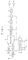
- FIG. 1 shows a vehicle-carried sound reproduction apparatus to which the present invention is applied.
- the vehicle-carried sound reproduction apparatus includes a player 1, for example, for a CD or an MD as a source of digital audio data, and an input selector circuit 4 to which digital audio data outputted from the player 1 is supplied.
- an FM tuner 2 As a source of an analog audio signal, for example, an FM tuner 2 is provided. An analog audio signal outputted from the tuner 2 is supplied to an A/D converter circuit 3, by which it is converted into digital audio data. The digital audio data is supplied to the selector circuit 4.
- the selector circuit 4 selects one of the digital audio data supplied thereto and supplies the selected digital audio data to a digital correction circuit 5, by which predetermined correction processing is performed for the digital audio data.
- the digital correction circuit 5 is formed from a DSP (digital signal processor) including a low frequency region correction circuit 51, a resonance reducing circuit 52, a correction amount adjusting circuit 53, and a correction filter circuit 54 and corrects the digital audio data so that a sound image reproduced by a speaker system may be positioned at an aimed position.
- DSP digital signal processor
- the corrected digital audio data is supplied to a D/A converter circuit 6, by which it is converted into an analog audio signal.
- the analog audio signal is supplied through an attenuator circuit 7 for sound volume adjustment and an output amplifier 8 to a pair of speakers 9L and 9R for the left and right channels.
- the speakers 9L and 9R are disposed or can be disposed, for example, at the positions 1 ⁇ shown in FIG. 9A.
- the speakers 9L and 9R are disposed at lower portions of the front doors on the left and right sides of a vehicle, respectively.
- the vehicle-carried sound reproduction apparatus further includes a microcomputer 11 for system control. If one of a plurality of operation keys 12 is operated, then the player 1, tuner 2, input selector circuit 4 or attenuator circuit 7 is controlled by the microcomputer 11 in response to the key operation so that the source or the sound volume is varied.
- reproduction sound of a CD, an MD or a broadcast is outputted from the speakers 9L and 9R.
- a sound image formed by the reproduction sound is positioned, for example, at the height of the eyes of the listener as a result of correction processing of the digital correction circuit 5 even if the speakers 9L and 9R are positioned at the positions 1 ⁇ shown in FIG. 9A.
- the digital correction circuit 5 corrects digital audio data so that a sound image may be positioned at the height of the eyes of the listener as described above.
- the correction is realized by use of a transfer function determined taking also an auditory sense characteristic from the speakers to the drums of the listener into consideration, that is, a head transfer function (HTRF).
- HTRF head transfer function
- the head transfer function can generally be measured in the following manner. In particular:
- the position of a sound image is corrected by the digital correction circuit 5 in such a manner as described above, and in the digital correction circuit 5 of FIG. 2, the correction filter circuit 54 executes the correction.
- the correction filter circuit 54 corrects digital audio data in accordance with the head transfer functions determined in (B) and (C) above.
- the position of a sound image by the speakers 9L and 9R mounted at the positions 1 ⁇ of the doors adjacent the front seats is corrected to the position of the sound image by the speaker which is positioned at the ideal position 3 ⁇ .
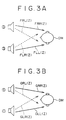
- head transfer functions HTRF obtained by the measurement and analysis by the steps of the paragraphs (A) to (C) above are such as given below and as illustrated also in FIGS. 3A and 3B:
- the position 3 ⁇ is the position of a speaker for realizing an ideal sound field or sound image
- the position 1 ⁇ is the position of the speaker 9L or 9R disposed actually.
- each of the head transfer functions is presented in a complex number.
- input audio signals are defined by parameters XL(Z), XR(Z), YL(Z) and YR(Z) as follows:
- the location of the dummy head DM when a head transfer function is measured preferably is a central position of the front seats in the vehicle chamber or a central position in the vehicle chamber. Where the dummy head DM is located in this manner, the correction difference between different seats is minimized and a correction effect can be anticipated at any seat.
- the coefficient k increases, then the different components of the second terms are emphasized, and accordingly, the feeling of expansion of the reproduction sound field is promoted.
- the correction filter circuit 54 can be formed from a filter having characteristics represented by the expressions (7) and (8), an addition circuit and a subtraction circuit, and a level control circuit.
- the correction filter circuit 54 shown in FIG. 2 is constructed based on the concept just described. In this instance, digital audio data from the correction amount adjusting circuit 53 are used as the input signals XL(Z) and XR(Z) to the correction filter circuit 54, and the output signals of the correction filter circuit 54 are the signals YL(Z) and YR(Z).
- the input signals XL(Z) and XR(Z) are inputted to a subtraction circuit 541A and an addition circuit 541B, by which a difference signal and a sum signal are formed, respectively.
- the difference signal is supplied to a level control circuit 541C, by which level control corresponding to the coefficient k in the expressions (11) and (12) is performed for the difference signal, and the resulting difference signal is supplied to a filter circuit 542M.
- the sum signal is supplied to a filter circuit 542P.
- the filter circuits 542M and 542P are each formed from a FIR filter and have transfer characteristics represented by the expressions (8) and (7) given hereinabove, respectively.
- Output signals of the filter circuits 542M and 542P are supplied at predetermined ratios to a addition circuit 543A and a subtraction circuit 543B, by which output signals YL(Z) and YR(Z) are formed, respectively.
- the signals YL(Z) and YR(Z) are supplied to the D/A converter circuit 6 in the next stage.
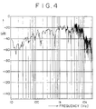
- FIG. 4 illustrates an example of measurement of the impulse response and represents a result of measurement of the impulse response from the speaker disposed at the position 1 ⁇ of the left door adjacent a front seat of the vehicle to the left ear of the dummy head DM disposed at the center of the front seats.
- the amplitude of the result of the measurement of FIG. 4 is smoothed on the frequency axis to remove steep peaks and dips to utilize a general tendency of the impulse response.
- characteristics of curves A and B of FIG. 5 are obtained, and the filter circuits 542M and 542P are constructed in accordance with the characteristics of the curves A and B.
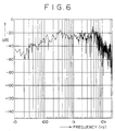
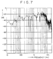
- FIGS. 6 and 7 show different examples of a result of measurement of the impulse response.
- FIG. 6 shows a result of a measurement of the impulse response from the speaker disposed at the position 1 ⁇ of the door adjacent the front left seat of the vehicle to the left ear of the dummy head DM disposed on the front left seat.
- FIG. 7 shows a result of a measurement of the impulse response from the speaker disposed at the position 1 ⁇ of the door adjacent the front left seat of the vehicle to the left ear of the dummy head DM disposed on the front right seat.
- the filter circuits 542M and 542P are constructed in accordance with the characteristics of the straight line C and the curve B.
- phase minimization As a method of reducing the order number of a filter, a technique called phase minimization is available.
- phase minimization is performed for each of calculations of the numerator and the denominator first, and then division is performed to reduce the order number of the filter circuits 542M and 542P.
- the order number of the filter circuits 542M and 542P can be reduced, and as a result, the correction filter circuit 54 can be simplified.
- the digital correction circuit 5 includes the low frequency region correction circuit 51 so that balance correction of output sound may be performed.
- the low frequency region correction circuit 51 includes a pair of band reinforcement filters 51L and 51R interposed in signal lines for digital audio data (the signals XL(Z) and XR(Z)).
- band reinforcement filters 51L and 51R have, for example, such characteristics as
- the inside of the vehicle chamber is a closed space having a complicated configuration.
- a "vehicle chamber resonance phenomenon" wherein standing waves are formed resonating with sound outputted from a speaker occurs.
- the frequency at which the influence of the vehicle chamber resonance phenomenon appeared most significantly was generally a frequency band 800 Hz or lower. Accordingly, if the output level of sound in the frequency band of 100 Hz to 800 Hz is dropped, then the "confined feeling" can be reduced without having much influence on the quality feeling of a music signal.
- the digital correction circuit 5 of FIG. 2 includes the resonance reducing circuit 52 in order to reduce resonance.
- the resonance reducing circuit 52 includes a pair of band attenuation filters 52L and 52R interposed in the signal lines for digital audio data (the signals XL(Z) and XR(Z)).
- the band attenuation filters 52L and 52R have, for example, such characteristics as
- the digital correction circuit 5 includes the correction amount adjusting circuit 53 so that sound in a high frequency region when the sound volume is great may be suppressed.
- the correction amount adjusting circuit 53 includes a pair of high frequency attenuation filters (shelving filters) 53L and 53R interposed in the signal lines for digital audio data (the signals XL(Z) and XR(Z)).
- the high frequency attenuation filters 53L and 53R have, for example, such characteristics as
- the attenuation amount of the attenuator circuit 7 is controlled by the microcomputer 11 so that the sound volume of reproduction sound is adjusted.
- the attenuation amounts of the high frequency attenuation filters 53L and 53R in the high frequency region are controlled simultaneously by the microcomputer 11 so that, as the sound volume increases, the attenuation amounts of the high frequency attenuation filters 53L and 53R in the high frequency region increase.
- the digital correction circuit 5 of FIG. 2 includes the level control circuit 541C.
- the level control circuit 541C controls the level of a difference component to be supplied from the subtraction circuit 541A to the filter circuit 542M in accordance with the coefficient k in response to an instruction from the microcomputer 11. Accordingly, the feeling of spatial expansion of reproduction sound can be emphasized.
- the level of the difference component is increased to emphasize the feeling of expansion, then the sound generally sounds as if the sound volume had increased. Therefore, in the reproduction apparatus of FIG. 1, when the level of the reference component is controlled by the level control circuit 541C, simultaneously the level of the audio signal is corrected by the attenuator circuit 7 for sound volume adjustment, and consequently, the sound volume of reproduction sound is corrected.
- the position of the sound image is corrected to the height of the eyes and a sound field which provides a sufficient feeling of expansion is regenerated.
- the feeling of spatial expansion of a sound field can be corrected by controlling the level of the difference component. Furthermore, optimum correction can be performed in accordance with the sound volume level. Besides, the digital correction circuit 5 can be simplified, and even where a DSP having a comparatively low processing capability is used for the digital correction circuit 5, an anticipated object can be achieved. Further, only if a transfer function is measured, optimum correction can be performed with any model of a vehicle having any configuration.
- the correction filter circuit can be universally used as a correction filter circuit whose application is not limited to a specific model of a vehicle.
- sound in a low frequency region is outputted with intensified power from the speakers for both of the front seats and the rear seats of the vehicle. Since generally the speakers on the rear seat side in most cases have a greater diameter, the performance of the speakers in the vehicle chamber can be exhibited sufficiently with regard to the output for sound in a low frequency region.
- speakers for the front seats are in most cases disposed at lower positions 1 ⁇ of the front doors and speakers for the rear seats are in most cases disposed at lower positions 2 ⁇ of the rear doors as described hereinabove with reference to FIG. 9A, or speakers for rear doors are frequently disposed at positions 4 ⁇ of a rear tray as shown in FIG. 9B.
- a reproduction sound outputted from the speaker disposed on the right front side arrives first, and then reproduction sounds outputted from the other speakers successively arrive after some delays of time. Accordingly, the passenger hears the reproduction sounds having phases displaced from one another. As a result, a feeling of a clearly positioned sound image cannot be obtained.
- the processing of correcting the height of a sound image to be reproduced to the height of the eyes of a passenger is omitted to simplify the circuit construction while a sound characteristic at a seated position of the passenger is augmented.
- digital audio data selected by a selector circuit 4 are supplied to a pair of delay circuits 57L and 57R, by which they are delayed by predetermined times.
- the thus delayed digital audio data are supplied to a D/A converter circuit 6, by which they are converted into analog audio signals.
- the audio signals are supplied to a pair of speakers 9L and 9R for the left and right channels through an attenuator circuit 7 for sound volume adjustment and an output amplifier 8.
- the speakers 9L and 9R are disposed, for example, at the positions 1 ⁇ described hereinabove with reference to FIGS. 9A and 9B.
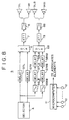
- the digital audio data selected by the input selector circuit 4 are supplied to a pair of high frequency attenuation filters (shelving filters) 56LB and 56RB.
- the high frequency attenuation filters 56LB and 56RB are provided to attenuate high frequency components, which act to displace a sound image rearwardly as described hereinabove, and have, for example, the following characteristics:
- the digital audio data outputted from the high frequency attenuation filters 56LB and 56RB are supplied to a pair of delay circuits 57LB and 57RB, by which they are delayed by predetermined times. Then, the delayed digital audio data are supplied through a pair of the delay circuits 58L and 58R to a D/A converter 6B, by which they are converted into analog audio signals.
- the audio signals are supplied a pair of speakers 9LB and 9RB for the left and right channels through an attenuator circuit 7B for sound volume adjustment and an output amplifier 8B. It is to be noted that the speakers 9LB and 9RB are disposed, for example, at the positions 2 ⁇ of FIG. 9A or the positions 4 ⁇ of FIG. 9B.
- the high frequency attenuation filters 56LB and 56RB attenuate high frequency components which displace the sound image rearwardly as described above, but output low frequency components, which do not relate much to the positioning of the sound image, as they are.
- the delay circuits 57L, 57R, 57LB and 57RB are provided to adjust the phases of reproduction sounds to be outputted from the speakers 9L, 9R, 9LB and 9RB in accordance with the seated position of a passenger.
- the attenuation amounts of sound in a high frequency region of the high frequency attenuation filters 56LB and 56RB and the delay times of the delay circuits 57L, 57R, 57LB and 57RB are controlled by the microcomputer 11 in response to the operation of the key.
- the delay circuits 58LB and 58RB are provided to cause reproduction sounds outputted from the speakers 9L and 9R at the forward positions to arrive at a passenger seated on a front seat relatively earlier by 10 msec to 20 msec than reproduction sounds outputted from the speakers 9LB and 9RB at the rearward positions.
- the phases when reproduction sounds outputted from the speakers 9L, 9R, 9LB and 9RB arrive at a passenger can be adjusted by the delay circuits 57L to 57RB, and accordingly, a sound image can be positioned definitely.
- the auditory sense of a human being has a preceding sound effect (Haas effect), that is, a characteristic that a sound arriving prior by a time of approximately 10 msec to 20 msec is perceived emphatically, by the delay circuits 58LB and 58RB, since reproduction sounds outputted from the speakers 9L and 9R at the forward positions precede reproduction sounds outputted from the speakers 9LB and 9RB at the rearward positions relatively by approximately 10 msec to 20 msec, the reproduction sounds outputted from the speakers 9L and 9R at the front positions are emphasized. Consequently, a sound image can be positioned forwardly without decreasing the overall sound volume.
- a preceding sound effect that is, a characteristic that a sound arriving prior by a time of approximately 10 msec to 20 msec is perceived emphatically
- the delay circuits 58LB and 58RB since reproduction sounds outputted from the speakers 9L and 9R at the forward positions precede reproduction sounds outputted from the speakers 9LB and 9RB at the rearward positions relatively by approximately 10 msec to
- the overall sound pressure level does not drop or the thickness of sound in the low frequency region is not lost.
- the rear speakers generally have a diameter greater than that of the rear speakers, the performance of the speakers 9LB and 9RB can be exhibited sufficiently for the low frequency outputs.
- reproduction sounds outputted from the speakers 9L and 9R are perceived emphatically due to the preceding sound effect, even where signal processing such as graphic equalizer processing can be set only to signal lines for audio signals to be supplied to the front speakers 9L and 9R from a restriction of a DSP or the like, the effect acts so as to be effective for the entire vehicle chamber.
- the delay circuits 57LB and 57RB and the delay circuits 58LB and 58RB of the digital correction circuit 5 of FIG. 8 may be integrated with each other, respectively.
- a seated position of a passenger is inputted using the operation keys 12, also it is possible to detect a seated position of a passenger by means of an infrared ray sensor provided in the vehicle chamber or a pressure sensor provided for a seat and control the high frequency attenuation filters 56LB and 56RB and the delay circuits 57L to 57RB by means of the microcomputer 11 in accordance with a detection output of the sensor so that they may have characteristics suitable for the seated position.
Landscapes
- Engineering & Computer Science (AREA)
- Physics & Mathematics (AREA)
- Acoustics & Sound (AREA)
- Signal Processing (AREA)
- Multimedia (AREA)
- Mechanical Engineering (AREA)
- Stereophonic System (AREA)
- Fittings On The Vehicle Exterior For Carrying Loads, And Devices For Holding Or Mounting Articles (AREA)
- Stereophonic Arrangements (AREA)
Applications Claiming Priority (4)
| Application Number | Priority Date | Filing Date | Title |
|---|---|---|---|
| JP12861799 | 1999-05-10 | ||
| JP12861799 | 1999-05-10 | ||
| JP26306499 | 1999-09-17 | ||
| JP11263064A JP2001028799A (ja) | 1999-05-10 | 1999-09-17 | 車載用音響再生装置 |
Publications (3)
| Publication Number | Publication Date |
|---|---|
| EP1052877A2 true EP1052877A2 (de) | 2000-11-15 |
| EP1052877A3 EP1052877A3 (de) | 2005-03-23 |
| EP1052877B1 EP1052877B1 (de) | 2007-10-24 |
Family
ID=26464226
Family Applications (1)
| Application Number | Title | Priority Date | Filing Date |
|---|---|---|---|
| EP00303905A Expired - Lifetime EP1052877B1 (de) | 1999-05-10 | 2000-05-09 | In einem Fahrzeug getragenes Gerät zur Schallwiedergabe |
Country Status (8)
| Country | Link |
|---|---|
| US (1) | US6498856B1 (de) |
| EP (1) | EP1052877B1 (de) |
| JP (1) | JP2001028799A (de) |
| KR (1) | KR100718478B1 (de) |
| CN (1) | CN1158899C (de) |
| BR (1) | BR0002098A (de) |
| CA (1) | CA2307913C (de) |
| DE (1) | DE60036832T2 (de) |
Cited By (6)
| Publication number | Priority date | Publication date | Assignee | Title |
|---|---|---|---|---|
| US6937733B2 (en) | 2001-10-11 | 2005-08-30 | Hyundai Motor Company | Audio system with a phase adjustment circuit |
| EP1596627A3 (de) * | 2004-05-04 | 2005-12-07 | Bose Corporation | Gerät zur Wiedergabe von Zentralkanalinformationen in einem Mehrkanaltonsystem für ein Fahrzeug |
| US8045743B2 (en) | 2005-09-12 | 2011-10-25 | Bose Corporation | Seat electroacoustical transducing |
| US8325936B2 (en) | 2007-05-04 | 2012-12-04 | Bose Corporation | Directionally radiating sound in a vehicle |
| US8724827B2 (en) | 2007-05-04 | 2014-05-13 | Bose Corporation | System and method for directionally radiating sound |
| US9100749B2 (en) | 2007-05-04 | 2015-08-04 | Bose Corporation | System and method for directionally radiating sound |
Families Citing this family (30)
| Publication number | Priority date | Publication date | Assignee | Title |
|---|---|---|---|---|
| JP2002199500A (ja) * | 2000-12-25 | 2002-07-12 | Sony Corp | 仮想音像定位処理装置、仮想音像定位処理方法および記録媒体 |
| US6804565B2 (en) | 2001-05-07 | 2004-10-12 | Harman International Industries, Incorporated | Data-driven software architecture for digital sound processing and equalization |
| US7447321B2 (en) | 2001-05-07 | 2008-11-04 | Harman International Industries, Incorporated | Sound processing system for configuration of audio signals in a vehicle |
| US7451006B2 (en) | 2001-05-07 | 2008-11-11 | Harman International Industries, Incorporated | Sound processing system using distortion limiting techniques |
| US7440578B2 (en) * | 2001-05-28 | 2008-10-21 | Mitsubishi Denki Kabushiki Kaisha | Vehicle-mounted three dimensional sound field reproducing silencing unit |
| US6999590B2 (en) * | 2001-07-19 | 2006-02-14 | Sunplus Technology Co., Ltd. | Stereo sound circuit device for providing three-dimensional surrounding effect |
| CA2773294C (en) | 2002-05-03 | 2013-03-12 | Harman International Industries, Incorporated | Sound detection and localization system |
| JP4627973B2 (ja) * | 2003-07-29 | 2011-02-09 | 富士通テン株式会社 | スピーカ装置 |
| US8638946B1 (en) * | 2004-03-16 | 2014-01-28 | Genaudio, Inc. | Method and apparatus for creating spatialized sound |
| US8031891B2 (en) * | 2005-06-30 | 2011-10-04 | Microsoft Corporation | Dynamic media rendering |
| EP1902532A4 (de) * | 2005-07-14 | 2012-08-22 | Scosche Ind Inc | Drahtlose medienquelle zur kommunikation mit einrichtungen auf dem datenbus eines fahrzeugs |
| US8520873B2 (en) * | 2008-10-20 | 2013-08-27 | Jerry Mahabub | Audio spatialization and environment simulation |
| US9197977B2 (en) * | 2007-03-01 | 2015-11-24 | Genaudio, Inc. | Audio spatialization and environment simulation |
| CN101494819B (zh) * | 2008-01-23 | 2012-11-28 | 凌阳科技股份有限公司 | 汽车虚拟环绕音响系统 |
| CN104960465B (zh) * | 2010-03-25 | 2017-11-28 | 日本先锋公司 | 模拟声产生装置以及模拟声产生方法 |
| KR20120004909A (ko) | 2010-07-07 | 2012-01-13 | 삼성전자주식회사 | 입체 음향 재생 방법 및 장치 |
| JP2011205687A (ja) * | 2011-06-09 | 2011-10-13 | Pioneer Electronic Corp | 音声調整装置 |
| JP5668765B2 (ja) | 2013-01-11 | 2015-02-12 | 株式会社デンソー | 車載音響装置 |
| US9088842B2 (en) | 2013-03-13 | 2015-07-21 | Bose Corporation | Grille for electroacoustic transducer |
| US9327628B2 (en) | 2013-05-31 | 2016-05-03 | Bose Corporation | Automobile headrest |
| JP6216553B2 (ja) * | 2013-06-27 | 2017-10-18 | クラリオン株式会社 | 伝搬遅延補正装置及び伝搬遅延補正方法 |
| EP2892250A1 (de) * | 2014-01-07 | 2015-07-08 | Fraunhofer-Gesellschaft zur Förderung der angewandten Forschung e.V. | Vorrichtung und Verfahren zur Erzeugung einer Vielzahl von Audiokanälen |
| US9699537B2 (en) | 2014-01-14 | 2017-07-04 | Bose Corporation | Vehicle headrest with speakers |
| JP6609407B2 (ja) * | 2014-12-22 | 2019-11-20 | 新日本無線株式会社 | オーディオ信号再生装置およびオーディオ信号処理方法 |
| WO2016157388A1 (ja) * | 2015-03-30 | 2016-10-06 | パイオニア株式会社 | 携帯端末、サーバ、音場測定データ提供方法、及び、プログラム |
| JP6942013B2 (ja) * | 2017-09-19 | 2021-09-29 | 株式会社東海理化電機製作所 | スイッチ装置 |
| CN111492667B (zh) * | 2017-12-19 | 2021-12-31 | 株式会社索思未来 | 声学系统、声学控制装置以及控制方法 |
| EP3742762B1 (de) * | 2018-01-19 | 2022-10-26 | JVCKenwood Corporation | Wiedergabevorrichtung, wiedergabeverfahren und lautsprechersystem an bord eines fahrzeuges |
| CN109195072B (zh) * | 2018-11-21 | 2021-10-12 | 广州小鹏汽车科技有限公司 | 基于汽车的音频播放控制系统及方法 |
| US10856082B1 (en) * | 2019-10-09 | 2020-12-01 | Echowell Electronic Co., Ltd. | Audio system with sound-field-type nature sound effect |
Family Cites Families (36)
| Publication number | Priority date | Publication date | Assignee | Title |
|---|---|---|---|---|
| JPS5442102A (en) * | 1977-09-10 | 1979-04-03 | Victor Co Of Japan Ltd | Stereo reproduction system |
| JPS61230600A (ja) * | 1985-04-05 | 1986-10-14 | Nissan Motor Co Ltd | 音響装置 |
| JPH0746880B2 (ja) * | 1986-02-20 | 1995-05-17 | 三菱電機株式会社 | 音場創造装置 |
| US4893342A (en) * | 1987-10-15 | 1990-01-09 | Cooper Duane H | Head diffraction compensated stereo system |
| JPH0255500A (ja) * | 1988-08-20 | 1990-02-23 | Matsushita Electric Ind Co Ltd | 圧電スピーカ装置 |
| JPH02305098A (ja) * | 1989-05-18 | 1990-12-18 | Fujitsu Ten Ltd | 車室内音場構成装置 |
| JPH0329500A (ja) * | 1989-06-26 | 1991-02-07 | Mazda Motor Corp | 車両用オーディオ装置 |
| US5305386A (en) * | 1990-10-15 | 1994-04-19 | Fujitsu Ten Limited | Apparatus for expanding and controlling sound fields |
| JPH04158700A (ja) * | 1990-10-23 | 1992-06-01 | Clarion Co Ltd | 車載用音響装置 |
| JPH04238500A (ja) * | 1991-01-22 | 1992-08-26 | Sharp Corp | サラウンド信号処理回路 |
| JPH04284100A (ja) * | 1991-03-12 | 1992-10-08 | Clarion Co Ltd | 車室内音場再生装置 |
| JPH04299398A (ja) * | 1991-03-28 | 1992-10-22 | Sony Corp | 車載用オーディオ装置 |
| JPH04334200A (ja) * | 1991-05-09 | 1992-11-20 | Onkyo Corp | 車載用ステレオ再生装置 |
| JPH04364700A (ja) * | 1991-06-12 | 1992-12-17 | Matsushita Electric Ind Co Ltd | 音場補正装置 |
| JPH05153687A (ja) * | 1991-11-28 | 1993-06-18 | Nissan Motor Co Ltd | 複合感覚評価用ダミーヘツド |
| JPH06311582A (ja) * | 1993-04-23 | 1994-11-04 | Sony Corp | スピーカ装置 |
| JP2947441B2 (ja) * | 1993-07-30 | 1999-09-13 | 日本ビクター株式会社 | 音像定位処理装置 |
| US5754664A (en) * | 1993-09-09 | 1998-05-19 | Prince Corporation | Vehicle audio system |
| EP0666556B1 (de) * | 1994-02-04 | 2005-02-02 | Matsushita Electric Industrial Co., Ltd. | Schallfeldkontrollegerät und Kontrolleverfahren |
| JPH07241000A (ja) * | 1994-02-28 | 1995-09-12 | Victor Co Of Japan Ltd | 音像定位制御椅子 |
| US5684881A (en) * | 1994-05-23 | 1997-11-04 | Matsushita Electric Industrial Co., Ltd. | Sound field and sound image control apparatus and method |
| JPH08163688A (ja) * | 1994-12-01 | 1996-06-21 | Clarion Co Ltd | 車載用音場補正装置 |
| JPH08265899A (ja) * | 1995-01-26 | 1996-10-11 | Victor Co Of Japan Ltd | サラウンド信号処理装置及び映像音声再生装置 |
| JP3258195B2 (ja) * | 1995-03-27 | 2002-02-18 | シャープ株式会社 | 音像定位制御装置 |
| JPH0919000A (ja) * | 1995-06-28 | 1997-01-17 | Matsushita Electric Ind Co Ltd | 車載用オーディオ装置 |
| US5850453A (en) * | 1995-07-28 | 1998-12-15 | Srs Labs, Inc. | Acoustic correction apparatus |
| JPH0965496A (ja) * | 1995-08-30 | 1997-03-07 | Matsushita Electric Ind Co Ltd | 音響制御装置 |
| WO2004103023A1 (ja) * | 1995-09-26 | 2004-11-25 | Ikuichiro Kinoshita | 仮想音像定位用伝達関数表作成方法、その伝達関数表を記録した記憶媒体及びそれを用いた音響信号編集方法 |
| JPH09191500A (ja) * | 1995-09-26 | 1997-07-22 | Nippon Telegr & Teleph Corp <Ntt> | 仮想音像定位用伝達関数表作成方法、その伝達関数表を記録した記憶媒体及びそれを用いた音響信号編集方法 |
| US5883961A (en) * | 1996-01-26 | 1999-03-16 | Harman International Industries, Incorporated | Sound system |
| JP3618159B2 (ja) * | 1996-02-28 | 2005-02-09 | 松下電器産業株式会社 | 音像定位装置およびそのパラメータ算出方法 |
| JPH1051890A (ja) * | 1996-07-31 | 1998-02-20 | Victor Co Of Japan Ltd | オーディオ信号伝送回路 |
| JPH10108293A (ja) * | 1996-09-27 | 1998-04-24 | Pioneer Electron Corp | 車載用スピーカシステム |
| JPH10126898A (ja) * | 1996-10-22 | 1998-05-15 | Kawai Musical Instr Mfg Co Ltd | 音像定位装置及び音像定位方法 |
| JP3402567B2 (ja) * | 1997-03-07 | 2003-05-06 | 日本ビクター株式会社 | マルチチャンネル信号処理方法 |
| US6243476B1 (en) * | 1997-06-18 | 2001-06-05 | Massachusetts Institute Of Technology | Method and apparatus for producing binaural audio for a moving listener |
-
1999
- 1999-09-17 JP JP11263064A patent/JP2001028799A/ja active Pending
-
2000
- 2000-05-08 US US09/566,529 patent/US6498856B1/en not_active Expired - Fee Related
- 2000-05-09 DE DE60036832T patent/DE60036832T2/de not_active Expired - Lifetime
- 2000-05-09 EP EP00303905A patent/EP1052877B1/de not_active Expired - Lifetime
- 2000-05-09 CA CA002307913A patent/CA2307913C/en not_active Expired - Fee Related
- 2000-05-10 KR KR1020000024946A patent/KR100718478B1/ko not_active Expired - Fee Related
- 2000-05-10 BR BR0002098-2A patent/BR0002098A/pt active Search and Examination
- 2000-05-10 CN CNB001178733A patent/CN1158899C/zh not_active Expired - Fee Related
Cited By (8)
| Publication number | Priority date | Publication date | Assignee | Title |
|---|---|---|---|---|
| US6937733B2 (en) | 2001-10-11 | 2005-08-30 | Hyundai Motor Company | Audio system with a phase adjustment circuit |
| EP1596627A3 (de) * | 2004-05-04 | 2005-12-07 | Bose Corporation | Gerät zur Wiedergabe von Zentralkanalinformationen in einem Mehrkanaltonsystem für ein Fahrzeug |
| US7561706B2 (en) | 2004-05-04 | 2009-07-14 | Bose Corporation | Reproducing center channel information in a vehicle multichannel audio system |
| US8045743B2 (en) | 2005-09-12 | 2011-10-25 | Bose Corporation | Seat electroacoustical transducing |
| US8325936B2 (en) | 2007-05-04 | 2012-12-04 | Bose Corporation | Directionally radiating sound in a vehicle |
| US8724827B2 (en) | 2007-05-04 | 2014-05-13 | Bose Corporation | System and method for directionally radiating sound |
| US9100749B2 (en) | 2007-05-04 | 2015-08-04 | Bose Corporation | System and method for directionally radiating sound |
| US9100748B2 (en) | 2007-05-04 | 2015-08-04 | Bose Corporation | System and method for directionally radiating sound |
Also Published As
| Publication number | Publication date |
|---|---|
| KR20000077218A (ko) | 2000-12-26 |
| CN1158899C (zh) | 2004-07-21 |
| CN1273192A (zh) | 2000-11-15 |
| BR0002098A (pt) | 2001-01-02 |
| CA2307913C (en) | 2010-02-02 |
| CA2307913A1 (en) | 2000-11-10 |
| DE60036832T2 (de) | 2008-08-07 |
| KR100718478B1 (ko) | 2007-05-16 |
| US6498856B1 (en) | 2002-12-24 |
| EP1052877B1 (de) | 2007-10-24 |
| EP1052877A3 (de) | 2005-03-23 |
| DE60036832D1 (de) | 2007-12-06 |
| JP2001028799A (ja) | 2001-01-30 |
Similar Documents
| Publication | Publication Date | Title |
|---|---|---|
| EP1052877B1 (de) | In einem Fahrzeug getragenes Gerät zur Schallwiedergabe | |
| US6501843B2 (en) | Automotive audio reproducing apparatus | |
| US7653203B2 (en) | Vehicle audio system surround modes | |
| US6901148B2 (en) | Automatic sound field correcting device | |
| US7466828B2 (en) | Vehicle audio system and reproduction method using same | |
| JP2005027273A (ja) | 音声補正装置 | |
| JPH10307592A (ja) | 車載用オーディオ装置のデータ配信システム | |
| US20050213786A1 (en) | Acoustic system for vehicle and corresponding device | |
| JP2007019980A (ja) | オーディオ静音化装置 | |
| EP2378795A1 (de) | Schallfeld-korrektursystem | |
| JPH0847078A (ja) | 車室内周波数特性自動補正方法 | |
| JPH08179786A (ja) | 車載用ステレオ再生装置 | |
| JPH0759200A (ja) | 音響再生装置 | |
| JP2009147815A (ja) | 音響空間制御装置及び音響空間制御方法 | |
| JP3369343B2 (ja) | 車載用オーディオ装置 | |
| JP2019198110A (ja) | 音量制御装置 | |
| JPH10303669A (ja) | 音量調節システム | |
| JP3260360B2 (ja) | 音像定位制御装置 | |
| JPH0528878Y2 (de) | ||
| JP2000151309A (ja) | 車載用音響装置 | |
| JP2528993B2 (ja) | 周波数特性制御装置 | |
| JP6556257B2 (ja) | 音量制御装置、音量制御方法、及び、プログラム | |
| EP3182723A1 (de) | Audiosignalverteilung | |
| JP2007184758A (ja) | 音響再生装置 | |
| HK1079034B (en) | System and method of vehicle audio surround modes |
Legal Events
| Date | Code | Title | Description |
|---|---|---|---|
| PUAI | Public reference made under article 153(3) epc to a published international application that has entered the european phase |
Free format text: ORIGINAL CODE: 0009012 |
|
| AK | Designated contracting states |
Kind code of ref document: A2 Designated state(s): AT BE CH CY DE DK ES FI FR GB GR IE IT LI LU MC NL PT SE |
|
| AX | Request for extension of the european patent |
Free format text: AL;LT;LV;MK;RO;SI |
|
| PUAL | Search report despatched |
Free format text: ORIGINAL CODE: 0009013 |
|
| AK | Designated contracting states |
Kind code of ref document: A3 Designated state(s): AT BE CH CY DE DK ES FI FR GB GR IE IT LI LU MC NL PT SE |
|
| AX | Request for extension of the european patent |
Extension state: AL LT LV MK RO SI |
|
| 17P | Request for examination filed |
Effective date: 20050907 |
|
| AKX | Designation fees paid |
Designated state(s): DE FR GB NL |
|
| GRAP | Despatch of communication of intention to grant a patent |
Free format text: ORIGINAL CODE: EPIDOSNIGR1 |
|
| GRAS | Grant fee paid |
Free format text: ORIGINAL CODE: EPIDOSNIGR3 |
|
| GRAA | (expected) grant |
Free format text: ORIGINAL CODE: 0009210 |
|
| AK | Designated contracting states |
Kind code of ref document: B1 Designated state(s): DE FR GB NL |
|
| REG | Reference to a national code |
Ref country code: GB Ref legal event code: FG4D |
|
| REF | Corresponds to: |
Ref document number: 60036832 Country of ref document: DE Date of ref document: 20071206 Kind code of ref document: P |
|
| ET | Fr: translation filed | ||
| PLBE | No opposition filed within time limit |
Free format text: ORIGINAL CODE: 0009261 |
|
| STAA | Information on the status of an ep patent application or granted ep patent |
Free format text: STATUS: NO OPPOSITION FILED WITHIN TIME LIMIT |
|
| 26N | No opposition filed |
Effective date: 20080725 |
|
| PGFP | Annual fee paid to national office [announced via postgrant information from national office to epo] |
Ref country code: FR Payment date: 20110607 Year of fee payment: 12 |
|
| PGFP | Annual fee paid to national office [announced via postgrant information from national office to epo] |
Ref country code: NL Payment date: 20110520 Year of fee payment: 12 Ref country code: GB Payment date: 20110520 Year of fee payment: 12 |
|
| PGFP | Annual fee paid to national office [announced via postgrant information from national office to epo] |
Ref country code: DE Payment date: 20110520 Year of fee payment: 12 |
|
| REG | Reference to a national code |
Ref country code: NL Ref legal event code: V1 Effective date: 20121201 |
|
| GBPC | Gb: european patent ceased through non-payment of renewal fee |
Effective date: 20120509 |
|
| REG | Reference to a national code |
Ref country code: FR Ref legal event code: ST Effective date: 20130131 |
|
| REG | Reference to a national code |
Ref country code: DE Ref legal event code: R119 Ref document number: 60036832 Country of ref document: DE Effective date: 20121201 |
|
| PG25 | Lapsed in a contracting state [announced via postgrant information from national office to epo] |
Ref country code: NL Free format text: LAPSE BECAUSE OF NON-PAYMENT OF DUE FEES Effective date: 20121201 |
|
| PG25 | Lapsed in a contracting state [announced via postgrant information from national office to epo] |
Ref country code: FR Free format text: LAPSE BECAUSE OF NON-PAYMENT OF DUE FEES Effective date: 20120531 Ref country code: GB Free format text: LAPSE BECAUSE OF NON-PAYMENT OF DUE FEES Effective date: 20120509 |
|
| PG25 | Lapsed in a contracting state [announced via postgrant information from national office to epo] |
Ref country code: DE Free format text: LAPSE BECAUSE OF NON-PAYMENT OF DUE FEES Effective date: 20121201 |