EP1053842A2 - Palette de moulage - Google Patents
Palette de moulage Download PDFInfo
- Publication number
- EP1053842A2 EP1053842A2 EP00500096A EP00500096A EP1053842A2 EP 1053842 A2 EP1053842 A2 EP 1053842A2 EP 00500096 A EP00500096 A EP 00500096A EP 00500096 A EP00500096 A EP 00500096A EP 1053842 A2 EP1053842 A2 EP 1053842A2
- Authority
- EP
- European Patent Office
- Prior art keywords
- section
- sections
- middle branch
- metal
- edges
- Prior art date
- Legal status (The legal status is an assumption and is not a legal conclusion. Google has not performed a legal analysis and makes no representation as to the accuracy of the status listed.)
- Granted
Links
Images

Classifications
-
- B—PERFORMING OPERATIONS; TRANSPORTING
- B28—WORKING CEMENT, CLAY, OR STONE
- B28B—SHAPING CLAY OR OTHER CERAMIC COMPOSITIONS; SHAPING SLAG; SHAPING MIXTURES CONTAINING CEMENTITIOUS MATERIAL, e.g. PLASTER
- B28B7/00—Moulds; Cores; Mandrels
- B28B7/0029—Moulds or moulding surfaces not covered by B28B7/0058 - B28B7/36 and B28B7/40 - B28B7/465, e.g. moulds assembled from several parts
- B28B7/0055—Mould pallets; Mould panels
Definitions
- the present invention refers to a shuttering tray or panel, of the kind intended to move on the guides of concrete precasting fixed presses, a tray that has been considerably improved in order to enhance its functional performances, specifically ensuring greater solidity between the two components of the tray (wood and metal section) so that they are solidly capable of withstanding the enormous pressures and vibrations to which they are subjected in the aforesaid presses for compacting the concrete, avoiding the usual jamming in the aforesaid guides.
- the trays for precastings of the type referred to in the previous paragraph are structured on the basis of a plurality of boards or strips fitted parallel to one another, in a coplanar arrangement, generally by means of multiple joints in dovetail fashion, in order to obtain a rectangular panel, of suitable dimensions, which will usually be from 900 x 500 x 30 mm to 1,500 x 1,500 x 50 mm, the opposing edges of the panel thus obtained, which have to slide on the guides of the concrete presses being reinforced with the aid of channelled sections, generally of galvanized plate, with a thickness in the region of 2 mm, which with a "U" section with a slightly narrowed mouth, previously cut and grooved on the corresponding marginal areas of the panel, are suitably attached to the latter.
- these channelled sections have their ends open with a simple flattening, or closed, by means of a detachable cover or by means of extending and bending its middle branch and fastening these closures with welding beads.
- the shuttering tray for concrete precasting presses that the invention proposes, based on a conventional basic structure, i.e. a panel with its edges for sliding on the concrete press guides reinforced by means of metal sections, focuses its characteristics on a special finishing piece or end closure for such metal sections, which solve the problems described previously in a completely satisfactory manner for the various aspects discussed.
- the aforementioned channelled metal sections have been designed to be closed at their ends by means of bending, specifically by means of an orthogonal bend in the middle branch of the section simultaneously with the bending of the lateral branches, which overlap outside the bend of its middle branch and which come directly into contact with one another at their edges.
- a multiple effect is achieved in this way, ranging from an absence of welds in the parts that directly affect the press guides to a significant stiffening of the ends of the section, the participation of superimposed "triple layers" of plate at each of the said ends, and including a marked rounding of the lateral edges of each end of the section, which ensures a complete absence of risk of jamming of the trays on the concrete press guides.
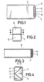
- Figure 1. Shows a side elevation view of one of the ends of the channelled metal section that forms part of the precasting tray forming the subject of the present invention.
- Figure 2. Shows an axial view of the section represented in the previous figure.
- Figure 3. Shows a detail in section along the line of section A - B of figure 2.
- Figure 4.- Shows another side elevation view of the section represented in figure 1, but on its inside face or opposite that shown in the said figure.
- the concrete precasting shuttering tray proposed by the invention is formed, like any conventional tray of this type, by means of a panel (1) composed of a plurality of boards or planks, suitably fixed together by means of tongue-and-grooved joints in multiple dovetails, a panel presenting two opposing edges (2) rebated on both sides, forming steps provided with a groove (3) on its edge, for connecting a metal, channelled "U” section (4) with its narrow mouth, a mouth that is fitted into the aforesaid groove (3), these metal sections (4) forming the means of stiffening of the tray and especially the means of sliding on the guides of the concrete press for which the tray is intended.
- the invention is focused on the fact that the traditional closure at each of the ends of the metal, channelled sections (4), is achieved, after their suitable overdimensioning, by means of simple bending, specifically by means of a bend (5) in its middle branch towards the concave area of the section, parallel to a bend (6 - 6') in its lateral branches until these contact at their free edges (7), thus achieving, as observed especially in figure 5, that the marginal areas of the tray intended to slide on the guides of the press present rounded edges (8) on their reinforcing sections, ensuring perfect sliding on the said guides, a perfectly flat external face (9) and finally a multilayer structure at each end of the metal sections (4), as observed especially in the section in figure 3, which considerably increases their mechanical strength.
- these metal, channelled sections (4) will be fixed to the panel (1), not only via the narrowing of its mouth that fits into the aforesaid grooves (3), but also by means of the traditional punchings (10) in its lateral branches, preferably cylindrical, which in their own shaping and due to the tearing of material generate insertion and fastening tabs in the wood.
Landscapes
- Engineering & Computer Science (AREA)
- Manufacturing & Machinery (AREA)
- Chemical & Material Sciences (AREA)
- Ceramic Engineering (AREA)
- Mechanical Engineering (AREA)
- Packaging Of Annular Or Rod-Shaped Articles, Wearing Apparel, Cassettes, Or The Like (AREA)
- Press-Shaping Or Shaping Using Conveyers (AREA)
- Forms Removed On Construction Sites Or Auxiliary Members Thereof (AREA)
- Moulds, Cores, Or Mandrels (AREA)
Applications Claiming Priority (2)
| Application Number | Priority Date | Filing Date | Title |
|---|---|---|---|
| ES9901287U | 1999-05-20 | ||
| ES9901287U ES1043213Y (es) | 1999-05-20 | 1999-05-20 | Bandeja de encofrado |
Publications (3)
| Publication Number | Publication Date |
|---|---|
| EP1053842A2 true EP1053842A2 (fr) | 2000-11-22 |
| EP1053842A3 EP1053842A3 (fr) | 2002-11-27 |
| EP1053842B1 EP1053842B1 (fr) | 2005-05-04 |
Family
ID=8308786
Family Applications (1)
| Application Number | Title | Priority Date | Filing Date |
|---|---|---|---|
| EP20000500096 Expired - Lifetime EP1053842B1 (fr) | 1999-05-20 | 2000-05-19 | Palette de moulage |
Country Status (4)
| Country | Link |
|---|---|
| EP (1) | EP1053842B1 (fr) |
| DE (1) | DE60019846T2 (fr) |
| ES (1) | ES1043213Y (fr) |
| PT (1) | PT1053842E (fr) |
Family Cites Families (5)
| Publication number | Priority date | Publication date | Assignee | Title |
|---|---|---|---|---|
| DE1876241U (de) * | 1963-05-02 | 1963-07-25 | Theodor Massenberg Fa | Schalungstafel. |
| US4030187A (en) * | 1976-05-27 | 1977-06-21 | Daley Thomas G | Method of making an object support member |
| EP0085029A1 (fr) * | 1982-01-22 | 1983-08-03 | Oskar Kästli | Panneau de coffrage |
| SE464768B (sv) * | 1989-10-27 | 1991-06-10 | Bo Allan Hjelm | Formlucka foer betonggjutning |
| BE1009036A3 (nl) * | 1994-06-07 | 1996-11-05 | Jan Construct Nv | Onderlegplank. |
-
1999
- 1999-05-20 ES ES9901287U patent/ES1043213Y/es not_active Expired - Fee Related
-
2000
- 2000-05-19 DE DE2000619846 patent/DE60019846T2/de not_active Expired - Lifetime
- 2000-05-19 PT PT00500096T patent/PT1053842E/pt unknown
- 2000-05-19 EP EP20000500096 patent/EP1053842B1/fr not_active Expired - Lifetime
Also Published As
| Publication number | Publication date |
|---|---|
| PT1053842E (pt) | 2005-07-29 |
| EP1053842B1 (fr) | 2005-05-04 |
| DE60019846T2 (de) | 2006-02-02 |
| ES1043213Y (es) | 2000-05-01 |
| DE60019846D1 (de) | 2005-06-09 |
| ES1043213U (es) | 1999-11-16 |
| EP1053842A3 (fr) | 2002-11-27 |
Similar Documents
| Publication | Publication Date | Title |
|---|---|---|
| KR20020045603A (ko) | 고강도 벽과 덮개 조립체를 위한 구조용 샌드위치 패널을 제조하기 위한 방법 | |
| EP1053842A2 (fr) | Palette de moulage | |
| JPH03154743A (ja) | 伸縮自在カバー及びその製法 | |
| JPH03161237A (ja) | 伸縮自在カバー及びその製法 | |
| US6574938B1 (en) | Constructional sandwich panel for high strength wall and covering assemblies, and method for making said panel | |
| JPS6344451B2 (fr) | ||
| HU219106B (hu) | Acéllemez ajtó | |
| US4076298A (en) | Vehicle side wall and method of making same | |
| JP2006504004A (ja) | 梁 | |
| US4924642A (en) | Device for mounting doors and windows | |
| GB2121848A (en) | Wall studs and connectors therefor | |
| EP0951079A4 (fr) | Cellule seche et procede de fabrication d'un boitier externe pour cette derniere | |
| US5750236A (en) | Apparatus and method for forming compound shaped surfaces | |
| US6457226B1 (en) | Process for beading sheet metal parts in a beading machine | |
| JP3031353U (ja) | シート定着用溝形材の接続構造及びジョイント片 | |
| US3101571A (en) | Universal nail tab for lock joint shingles | |
| JP7050386B2 (ja) | 車体構成部材の製造方法 | |
| JPH05137280A (ja) | 積層鉄心の製造方法 | |
| JPS628280Y2 (fr) | ||
| AU2004100903A4 (en) | A metal container, and its method of manufacture | |
| KR20180138162A (ko) | 금속 판재의 크림핑 접합 구조, 및 접합 방법 | |
| JPS61159232A (ja) | エキスパンドグレ−チングの製造方法 | |
| GB2300237A (en) | Nail plate | |
| JPS5836211B2 (ja) | 木材の屈折接続方法 | |
| JPH06158805A (ja) | 弧状笠木及びその製造方法 |
Legal Events
| Date | Code | Title | Description |
|---|---|---|---|
| PUAI | Public reference made under article 153(3) epc to a published international application that has entered the european phase |
Free format text: ORIGINAL CODE: 0009012 |
|
| AK | Designated contracting states |
Kind code of ref document: A2 Designated state(s): AT BE CH CY DE DK ES FI FR GB GR IE IT LI LU MC NL PT SE |
|
| AX | Request for extension of the european patent |
Free format text: AL;LT;LV;MK;RO;SI |
|
| PUAL | Search report despatched |
Free format text: ORIGINAL CODE: 0009013 |
|
| AK | Designated contracting states |
Kind code of ref document: A3 Designated state(s): AT BE CH CY DE DK ES FI FR GB GR IE IT LI LU MC NL PT SE |
|
| AX | Request for extension of the european patent |
Free format text: AL;LT;LV;MK;RO;SI |
|
| 17P | Request for examination filed |
Effective date: 20030522 |
|
| AKX | Designation fees paid |
Designated state(s): DE FR PT |
|
| 17Q | First examination report despatched |
Effective date: 20031217 |
|
| GRAP | Despatch of communication of intention to grant a patent |
Free format text: ORIGINAL CODE: EPIDOSNIGR1 |
|
| GRAS | Grant fee paid |
Free format text: ORIGINAL CODE: EPIDOSNIGR3 |
|
| GRAA | (expected) grant |
Free format text: ORIGINAL CODE: 0009210 |
|
| AK | Designated contracting states |
Kind code of ref document: B1 Designated state(s): DE FR PT |
|
| REG | Reference to a national code |
Ref country code: IE Ref legal event code: FG4D |
|
| REF | Corresponds to: |
Ref document number: 60019846 Country of ref document: DE Date of ref document: 20050609 Kind code of ref document: P |
|
| REG | Reference to a national code |
Ref country code: PT Ref legal event code: SC4A Effective date: 20050601 |
|
| PLBE | No opposition filed within time limit |
Free format text: ORIGINAL CODE: 0009261 |
|
| STAA | Information on the status of an ep patent application or granted ep patent |
Free format text: STATUS: NO OPPOSITION FILED WITHIN TIME LIMIT |
|
| ET | Fr: translation filed | ||
| 26N | No opposition filed |
Effective date: 20060207 |
|
| PGFP | Annual fee paid to national office [announced via postgrant information from national office to epo] |
Ref country code: PT Payment date: 20110512 Year of fee payment: 12 Ref country code: FR Payment date: 20110607 Year of fee payment: 12 |
|
| REG | Reference to a national code |
Ref country code: PT Ref legal event code: MM4A Free format text: LAPSE DUE TO NON-PAYMENT OF FEES Effective date: 20121119 |
|
| PG25 | Lapsed in a contracting state [announced via postgrant information from national office to epo] |
Ref country code: PT Free format text: LAPSE BECAUSE OF NON-PAYMENT OF DUE FEES Effective date: 20121119 |
|
| REG | Reference to a national code |
Ref country code: FR Ref legal event code: ST Effective date: 20130131 |
|
| PG25 | Lapsed in a contracting state [announced via postgrant information from national office to epo] |
Ref country code: FR Free format text: LAPSE BECAUSE OF NON-PAYMENT OF DUE FEES Effective date: 20120531 |
|
| REG | Reference to a national code |
Ref country code: DE Ref legal event code: R082 Ref document number: 60019846 Country of ref document: DE Representative=s name: PATENTANWAELTE CHARRIER RAPP & LIEBAU, DE |
|
| PGFP | Annual fee paid to national office [announced via postgrant information from national office to epo] |
Ref country code: DE Payment date: 20130524 Year of fee payment: 14 |
|
| REG | Reference to a national code |
Ref country code: DE Ref legal event code: R119 Ref document number: 60019846 Country of ref document: DE |
|
| REG | Reference to a national code |
Ref country code: DE Ref legal event code: R119 Ref document number: 60019846 Country of ref document: DE Effective date: 20141202 |
|
| PG25 | Lapsed in a contracting state [announced via postgrant information from national office to epo] |
Ref country code: DE Free format text: LAPSE BECAUSE OF NON-PAYMENT OF DUE FEES Effective date: 20141202 |