EP1053906B1 - Dispositif flottant pour un coussin de siège arrière d'un véhicule automobile - Google Patents
Dispositif flottant pour un coussin de siège arrière d'un véhicule automobile Download PDFInfo
- Publication number
- EP1053906B1 EP1053906B1 EP99121870A EP99121870A EP1053906B1 EP 1053906 B1 EP1053906 B1 EP 1053906B1 EP 99121870 A EP99121870 A EP 99121870A EP 99121870 A EP99121870 A EP 99121870A EP 1053906 B1 EP1053906 B1 EP 1053906B1
- Authority
- EP
- European Patent Office
- Prior art keywords
- pivot
- seat cushion
- frame
- stopper
- teeth portion
- Prior art date
- Legal status (The legal status is an assumption and is not a legal conclusion. Google has not performed a legal analysis and makes no representation as to the accuracy of the status listed.)
- Expired - Lifetime
Links
Images

Classifications
-
- B—PERFORMING OPERATIONS; TRANSPORTING
- B60—VEHICLES IN GENERAL
- B60N—SEATS SPECIALLY ADAPTED FOR VEHICLES; VEHICLE PASSENGER ACCOMMODATION NOT OTHERWISE PROVIDED FOR
- B60N2/00—Seats specially adapted for vehicles; Arrangement or mounting of seats in vehicles
- B60N2/02—Seats specially adapted for vehicles; Arrangement or mounting of seats in vehicles the seat or part thereof being movable, e.g. adjustable
-
- B—PERFORMING OPERATIONS; TRANSPORTING
- B60—VEHICLES IN GENERAL
- B60N—SEATS SPECIALLY ADAPTED FOR VEHICLES; VEHICLE PASSENGER ACCOMMODATION NOT OTHERWISE PROVIDED FOR
- B60N2/00—Seats specially adapted for vehicles; Arrangement or mounting of seats in vehicles
- B60N2/02—Seats specially adapted for vehicles; Arrangement or mounting of seats in vehicles the seat or part thereof being movable, e.g. adjustable
- B60N2/04—Seats specially adapted for vehicles; Arrangement or mounting of seats in vehicles the seat or part thereof being movable, e.g. adjustable the whole seat being movable
- B60N2/16—Seats specially adapted for vehicles; Arrangement or mounting of seats in vehicles the seat or part thereof being movable, e.g. adjustable the whole seat being movable height-adjustable
- B60N2/18—Seats specially adapted for vehicles; Arrangement or mounting of seats in vehicles the seat or part thereof being movable, e.g. adjustable the whole seat being movable height-adjustable the front or the rear portion of the seat being adjustable, e.g. independently of each other
- B60N2/1807—Seats specially adapted for vehicles; Arrangement or mounting of seats in vehicles the seat or part thereof being movable, e.g. adjustable the whole seat being movable height-adjustable the front or the rear portion of the seat being adjustable, e.g. independently of each other characterised by the cinematic
- B60N2/181—Rods
-
- B—PERFORMING OPERATIONS; TRANSPORTING
- B60—VEHICLES IN GENERAL
- B60N—SEATS SPECIALLY ADAPTED FOR VEHICLES; VEHICLE PASSENGER ACCOMMODATION NOT OTHERWISE PROVIDED FOR
- B60N2/00—Seats specially adapted for vehicles; Arrangement or mounting of seats in vehicles
- B60N2/02—Seats specially adapted for vehicles; Arrangement or mounting of seats in vehicles the seat or part thereof being movable, e.g. adjustable
- B60N2/04—Seats specially adapted for vehicles; Arrangement or mounting of seats in vehicles the seat or part thereof being movable, e.g. adjustable the whole seat being movable
- B60N2/16—Seats specially adapted for vehicles; Arrangement or mounting of seats in vehicles the seat or part thereof being movable, e.g. adjustable the whole seat being movable height-adjustable
- B60N2/18—Seats specially adapted for vehicles; Arrangement or mounting of seats in vehicles the seat or part thereof being movable, e.g. adjustable the whole seat being movable height-adjustable the front or the rear portion of the seat being adjustable, e.g. independently of each other
- B60N2/1807—Seats specially adapted for vehicles; Arrangement or mounting of seats in vehicles the seat or part thereof being movable, e.g. adjustable the whole seat being movable height-adjustable the front or the rear portion of the seat being adjustable, e.g. independently of each other characterised by the cinematic
- B60N2/1835—Seats specially adapted for vehicles; Arrangement or mounting of seats in vehicles the seat or part thereof being movable, e.g. adjustable the whole seat being movable height-adjustable the front or the rear portion of the seat being adjustable, e.g. independently of each other characterised by the cinematic pivoting about an axis located in the front
-
- B—PERFORMING OPERATIONS; TRANSPORTING
- B60—VEHICLES IN GENERAL
- B60N—SEATS SPECIALLY ADAPTED FOR VEHICLES; VEHICLE PASSENGER ACCOMMODATION NOT OTHERWISE PROVIDED FOR
- B60N2/00—Seats specially adapted for vehicles; Arrangement or mounting of seats in vehicles
- B60N2/02—Seats specially adapted for vehicles; Arrangement or mounting of seats in vehicles the seat or part thereof being movable, e.g. adjustable
- B60N2/04—Seats specially adapted for vehicles; Arrangement or mounting of seats in vehicles the seat or part thereof being movable, e.g. adjustable the whole seat being movable
- B60N2/16—Seats specially adapted for vehicles; Arrangement or mounting of seats in vehicles the seat or part thereof being movable, e.g. adjustable the whole seat being movable height-adjustable
- B60N2/18—Seats specially adapted for vehicles; Arrangement or mounting of seats in vehicles the seat or part thereof being movable, e.g. adjustable the whole seat being movable height-adjustable the front or the rear portion of the seat being adjustable, e.g. independently of each other
- B60N2/1889—Seats specially adapted for vehicles; Arrangement or mounting of seats in vehicles the seat or part thereof being movable, e.g. adjustable the whole seat being movable height-adjustable the front or the rear portion of the seat being adjustable, e.g. independently of each other and provided with braking systems
Definitions
- the present invention relates to a seat cushion of an automobile, more particularly a full floating device of a rear seat cushion for an automobile, which can fully adjust the angle of the rear seat cushion and can eliminate inconvenience caused by the wheel housing protruded into the inner space from the rear side of the automobile.
- both side of the rear seat cushion of the automobile contacts with the wheel housing in which a tire is positioned and the rear seat cushion cannot adjust the angle of thereof. Then the wheel housing is protruded into the inner space from the side body of the automobile. Therefore when the rear seat is fully occupied, the side passenger does not feel well by the wheel housing which contacts with the waist of the passenger.
- the passenger who are an old person or a little child can get damage by the wheel housing protruded into the inner space from the side body of the automobile when the automobile collides with other automobile etc,.
- the object of the present invention is to provide a full floating device of a rear seat cushion for an automobile that can adjust the angle thereof and can make passenger comfortable.
- the present invention to achieve the above object comprises a fixed frame fixed on a floor panel of an automobile, a pivot frame to which the end of the supporting bracket is linked by a pivot pin and on which a seat cushion is mounted, and an angle adjusting means pivoting the rear end of the pivot frame about the pivot pin in order to adjust the inclination of the seat cushion mounted on the pivot frame.
- the angle adjusting means comprises a first pivot arm to which the rear end of the fixed frame is pivotally linked; a second pivot arm to which one end of the first pivot arm and the rear end of the pivot frame are pivotally linked; a spring connected between a pivot shaft and a seat cushion frame so that the second pivot arm can be pivoted by the elastic force of the spring; and a lock release means for releasing the locking state of the pivot frame by the elastic force of the spring.
- the lock release means comprises a stopper to which the pivot frame is pivotally linked and having a teeth portion engaged with a teeth portion formed on the second pivot arm; a cam to which the pivot frame is pivotally linked and pushing a stopper so that the teeth portion of the stopper is disengaged with the teeth portion of the second pivot arm; a lever pivotally linked to the pivot frame; a link rotating the cam so that the teeth portion of the stopper and the teeth portion of the second pivot arm are selectively engage or disengaged each other by pivoting the lever, and a torsion spring mounted between the stopper and the pivot frame for giving a torque to the lever and returning it to the original position.
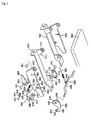
- Fig 1 shows an embodiment of a full floating device of a rear seat cushion for the automobile in accordance with the present invention.
- the full floating device comprises a fixed frame 100 fixed on a floor panel 10 of the automobile having a supporting bracket 110 provided a pivot hole 111 through which a pivot pin 120 is inserted, a pivot frame 200 having a pivot hole 210 through which the pivot pin 120 is so inserted that the end of the supporting bracket 110 is linked to the pivot frame 200 and a seat cushion 20 is mounted thereon, and an angle adjusting means 300 turning the rear end of the pivot frame 200 about the pivot pin 120 in order to adjust the inclination of the seat cushion mounted on the pivot frame 200.
- the angle adjusting means 300 comprises a first pivot arm 310 having pin holes 311, 312 through which a pivot pin 341 is inserted so that the first pivot arm 310 is linked to the rear end of the fixed frame 100, a second pivot arm 320 having a pin hole 321 through which the one end of the first pivot arm 310 is pivotally linked by a pivot pin 342 and having a pin hole 322 through which the rear end of the pivot frame 200 is pivotally linked by a pivot shaft 350, a spring 330 connected between a spring bracket 351 provided on the pivot shaft 350 and a bracket 221 provided on a seat cushion frame 260 so that the second pivot arm 320 is pivoted by the elastic force of the spring 330, and a lock release means 400 for releasing the locking state of the pivot frame 200 by the elastic force of the spring 330.
- a pin bracket 130 having a pin hole 131 is provided on rear end of the fixed frame 100 and a shaft hole 220 through which the pivot shaft 350 is inserted is formed on the pivot frame 200.
- the spring 330 pulls the pivot shaft 350 connected with the second pivot arm 320 so that the first pivot arm 310 and the second pivot arm 320 folded together are unfolded to have a certain angle there between.
- the lock release means 400 comprises a stopper 410 having a pin hole 411 through which the pivot frame 200 is pivotally linked to the one end of the stopper 410 and having a teeth portion 412 engaged with a teeth portion 323 formed on the plate part 324 of the second pivot arm 320, a cam 420 having pin hole 422 through which the pivot frame 200 is pivotally linked to the cam 420 and pushing the stopper 410 so that the teeth portion 412 of the stopper 410 is disengaged with the teeth portion 323 of the second pivot arm 320, a lever 430 having a pin hole 432 through which the pivot frame 200 is linked by a pin 430, a link 440 having pin holes 442, 443 through which a connecting pin 441 is inserted and turning the cam 420 so that the teeth portion 412 of the stopper 410 and the teeth portion 323 of the second pivot arm 320 are selectively engage or disengaged each other by pivoting the lever 430, and a torsion spring 450 mounted between the stopper 410 and the pivot frame 200
- the pivot frame 200 has three pin holes 230, 240, 250 through which the stopper 410, the lever 430 and the cam 420 are respectively linked by pin 460, 421, 431 each other. And the teeth portion of the stopper 410 is pivoted about the pivot shaft 350.
- a torsion spring 413 is mounted on the pin 460 that is inserted into a pin hole 411 formed on the stopper 410.
- the both ends of the spring 413 are respectively connected to the pivot frame 200 and the stopper 410. Therefore when the pushing force of the cam 420 that pushes the stopper 410 is released, the teeth portion 412 of the stopper 410 is elastically disengaged with the teeth portion 323 of the second pivot arm 320.
- the operator pulls the lever 430 upward. Then the link 440 linked to the lever 430 rotates the cam 420 that pushes the stopper 410 so that the teeth portion 412 of the stopper 410 is disengaged with the teeth portion 323 of the second pivot arm 320.
- the second pivot arm 320 is rotated by the elastic force of the spring 330 connected to the pivot shaft 350 and the second pivot arm 320 rotates the first pivot arm 310 connected to the second pivot arm 320. Then the folded the first arm 310 and the second arm 320 are unfolded and the rear end of the pivot frame 200 is rotated about the pivot pin 120. Therefore the rear end of the seat cushion mounted on the pivot frame 200 is moved upward and inclined forward as shown in Fig 3.
- the lever 430 is released. Then the cam 420 is rotated by the return force of the torsion spring 420 pushes the stopper 410, and the teeth portion of the stopper 410 is engaged with the teeth portion 323 of the second pivot arm 320.
- the position of the rear seat cushion is changed by the adjustment of the angle of the rear seat cushion, the rear seat cushion is positioned above the protrusion part of the wheel housing of the automobile. And the hindrance by the wheel housing to the passenger can be eliminated.
- full floating device in accordance with the present invention can adjust the angle and the position of the rear seat cushion, the passenger occupied on the rear seat can adjust the state of the rear seat cushion according to his conditions. Therefore the wheel housing protruded from the side body of the automobile does not hinder the passenger and the passenger can be comfortable.
Landscapes
- Engineering & Computer Science (AREA)
- Aviation & Aerospace Engineering (AREA)
- Transportation (AREA)
- Mechanical Engineering (AREA)
- Seats For Vehicles (AREA)
Claims (3)
- Dispositif flottant pour un coussin de siège arrière d'un véhicule automobile comprenant :un châssis fixe (100) pouvant être fixé sur un panneau de plancher (10) du véhicule automobile, comprenant une patte de fixation (110) ;un châssis de pivotement (200) auquel est reliée l'extrémité de la patte de fixation (110) par un axe de pivotement (120) et sur lequel est monté un coussin de siège (20) ; etun moyen de réglage d'angle (300) faisant pivoter l'extrémité arrière du châssis de pivotement (200) autour de l'axe de pivotement (120) afin de régler l'inclinaison du coussin de siège (20) monté sur le châssis de pivotement (200).
- Dispositif flottant pour un coussin de siège arrière d'un véhicule automobile selon la revendication 1,
dans lequel
le moyen de réglage d'angle comprend un premier bras de pivotement auquel est reliée de manière pivotante l'extrémité arrière du châssis fixe ; un deuxième bras de pivotement auquel sont reliées de manière pivotante une extrémité du premier bras de pivotement et l'extrémité arrière du châssis de pivotement ; un ressort raccordé entre un arbre de pivotement et un châssis de coussin de siège de telle sorte que le deuxième bras de pivotement puisse être pivoté par la force élastique du ressort ; et un moyen de déverrouillage pour débloquer l'état de verrouillage du châssis de pivotement par la force élastique du ressort. - Dispositif flottant pour un coussin de siège arrière d'un véhicule automobile selon la revendication 2,
dans lequel
le moyen de déverrouillage comprend un butoir auquel est relié de manière pivotante le châssis de pivotement et comprenant une partie dentée engagée avec une partiè dentée formée sur le deuxième arbre de pivotement ; une came à laquelle est relié de manière pivotante le châssis de pivotement et poussant un butoir de telle sorte que la partie dentée du butoir soit dégagée de la partie dentée du deuxième bras de pivotement ; un levier relié de manière pivotante au châssis de pivotement ; une liaison faisant tourner la came de telle sorte que la partie dentée du butoir et la partie dentée du deuxième bras de pivotement soient engagées l'une avec l'autre ou dégagées l'une de l'autre de manière sélective en faisant pivoter le levier ; et un ressort de torsion monté entre le butoir et le châssis de pivotement pour fournir un couple au levier et le faire retourner dans sa position d'origine.
Applications Claiming Priority (2)
| Application Number | Priority Date | Filing Date | Title |
|---|---|---|---|
| KR1019990017673A KR100317464B1 (ko) | 1999-05-17 | 1999-05-17 | 자동차용 시트쿠션 풀 플로우팅 장치 |
| KR9917673 | 1999-05-17 |
Publications (3)
| Publication Number | Publication Date |
|---|---|
| EP1053906A2 EP1053906A2 (fr) | 2000-11-22 |
| EP1053906A3 EP1053906A3 (fr) | 2001-08-22 |
| EP1053906B1 true EP1053906B1 (fr) | 2005-02-09 |
Family
ID=19585987
Family Applications (1)
| Application Number | Title | Priority Date | Filing Date |
|---|---|---|---|
| EP99121870A Expired - Lifetime EP1053906B1 (fr) | 1999-05-17 | 1999-11-04 | Dispositif flottant pour un coussin de siège arrière d'un véhicule automobile |
Country Status (7)
| Country | Link |
|---|---|
| US (1) | US6186572B1 (fr) |
| EP (1) | EP1053906B1 (fr) |
| JP (1) | JP2000335291A (fr) |
| KR (1) | KR100317464B1 (fr) |
| CN (1) | CN1109617C (fr) |
| AU (1) | AU734034B2 (fr) |
| DE (1) | DE69923664T2 (fr) |
Families Citing this family (13)
| Publication number | Priority date | Publication date | Assignee | Title |
|---|---|---|---|---|
| CA2279170A1 (fr) * | 1999-07-30 | 2001-01-30 | Donald A. Logan | Fauteuil roulant |
| WO2002020303A1 (fr) * | 2000-09-05 | 2002-03-14 | Johnson Controls Gmbh | Dispositif d'ajustement pour position en hauteur et en longueur et inclinaison d'un siege de vehicule |
| FR2822037B1 (fr) * | 2001-03-19 | 2003-06-27 | Faurecia Sieges Automobile | Dispositif d'assise comportant au moins un element de siege pivotant |
| JP3964172B2 (ja) * | 2001-10-10 | 2007-08-22 | 株式会社タチエス | 車両用シート |
| US7229118B2 (en) * | 2004-10-20 | 2007-06-12 | Lear Corporation | Slouch rear seat system |
| KR100636026B1 (ko) | 2005-03-14 | 2006-10-20 | 주식회사 오스템 | 차량용 시트의 높이조절기구 |
| KR20080045209A (ko) | 2005-09-15 | 2008-05-22 | 인티어 오토모티브 시팅 시스템스 게엠베하 | 시트 쿠션 로커 기구를 갖는 시트 조립체 |
| DE102006049676B4 (de) * | 2006-10-18 | 2008-12-11 | Sedus Stoll Ag | Stuhl mit neigbarem Sitz |
| US8042867B2 (en) * | 2009-11-02 | 2011-10-25 | B/E Aerospace, Inc. | Seat pan drop down link |
| PL3197710T3 (pl) | 2015-12-02 | 2019-01-31 | Assan Hanil Otomotiv Sanayi Ve Ticaret Anonim Sirketi | Mechanizm stopniowej regulacji pozycji kątowej powierzchni siedziska foteli samochodowych |
| US10081279B2 (en) * | 2016-04-12 | 2018-09-25 | Ford Global Technologies, Llc | Articulating thigh extension trim tensioning slider mechanism |
| US10286815B2 (en) * | 2017-04-03 | 2019-05-14 | Ford Global Technologies, Llc | H-point lift options for sleeper seats |
| KR102235026B1 (ko) * | 2019-10-28 | 2021-04-01 | 주식회사 서연이화 | 자동 폴딩이 가능한 차량용 시트 |
Family Cites Families (15)
| Publication number | Priority date | Publication date | Assignee | Title |
|---|---|---|---|---|
| DE1998856U (de) * | 1968-08-23 | 1968-12-19 | Hammerstein Gmbh C Rob | Verstelleinrichtung fuer fahrzeugsitze |
| US3695570A (en) * | 1969-10-22 | 1972-10-03 | Nissan Motor | Adjustable reclining seat |
| US3784147A (en) * | 1972-02-11 | 1974-01-08 | Coach & Car Equip Corp | Seat adjusting mechanism |
| JPS58156424A (ja) * | 1982-03-15 | 1983-09-17 | Honda Motor Co Ltd | 車両のシ−ト高さ調整装置 |
| IT1157779B (it) * | 1982-11-19 | 1987-02-18 | Keiper Italia Spa | Dispositivo di regolazione della posizione di un sedile di veicolo automobile |
| US4529158A (en) * | 1983-05-16 | 1985-07-16 | Itt Corporation | Adjustable vehicle seat mechanism |
| KR960004301B1 (ko) * | 1986-03-03 | 1996-03-30 | 후지 기꼬오 가부시끼가이샤 | 차량용 시이트 |
| DE3617810A1 (de) * | 1986-05-27 | 1987-12-03 | Keiper Recaro Gmbh Co | Fahrzeugsitz mit einer in ihrer hoehe und neigung verstellbaren sitzflaeche |
| ES2019705B3 (es) * | 1987-04-28 | 1991-07-01 | Sicam Spa | Un asiento delantero para un vehiculo a motor que solo tenga dos puertas laterales. |
| DE3807265A1 (de) * | 1988-03-05 | 1989-09-14 | Keiper Recaro Gmbh Co | Schulterstuetze fuer die rueckenlehne von fahrzeugsitzen |
| US4884843A (en) * | 1989-04-21 | 1989-12-05 | Chrysler Motors Corporation | Seat tilt mechanism |
| DE4429405A1 (de) * | 1994-08-09 | 1996-02-15 | Isringhausen Geb | Schwingfähig abgestützter Fahrzeugsitz mit einer Neigungs- und/oder Höhenverstellung der Sitzfläche |
| US5558386A (en) * | 1995-04-20 | 1996-09-24 | Chrysler Corporation | Asymmetrical wire hook latch arrangement |
| FR2748431B1 (fr) * | 1996-05-10 | 1998-07-24 | Faure Bertrand Equipements Sa | Mecanisme de reglage en position angulaire d'un bras articule sur un support |
| US6024411A (en) * | 1999-03-17 | 2000-02-15 | Daimlerchrysler Corporation | Seat mounted cupholder adapted for seat riser fold and tumble mechanism |
-
1999
- 1999-05-17 KR KR1019990017673A patent/KR100317464B1/ko not_active Expired - Fee Related
- 1999-11-02 AU AU57187/99A patent/AU734034B2/en not_active Ceased
- 1999-11-04 DE DE69923664T patent/DE69923664T2/de not_active Expired - Lifetime
- 1999-11-04 EP EP99121870A patent/EP1053906B1/fr not_active Expired - Lifetime
- 1999-11-05 JP JP11315232A patent/JP2000335291A/ja active Pending
- 1999-11-12 US US09/438,962 patent/US6186572B1/en not_active Expired - Lifetime
- 1999-11-16 CN CN99123588A patent/CN1109617C/zh not_active Expired - Fee Related
Also Published As
| Publication number | Publication date |
|---|---|
| AU5718799A (en) | 2000-11-23 |
| EP1053906A3 (fr) | 2001-08-22 |
| CN1109617C (zh) | 2003-05-28 |
| JP2000335291A (ja) | 2000-12-05 |
| AU734034B2 (en) | 2001-05-31 |
| US6186572B1 (en) | 2001-02-13 |
| KR20000074025A (ko) | 2000-12-05 |
| DE69923664D1 (de) | 2005-03-17 |
| KR100317464B1 (ko) | 2001-12-22 |
| EP1053906A2 (fr) | 2000-11-22 |
| CN1273921A (zh) | 2000-11-22 |
| DE69923664T2 (de) | 2006-03-16 |
Similar Documents
| Publication | Publication Date | Title |
|---|---|---|
| US6302485B1 (en) | Head rest device for vehicles | |
| US5765894A (en) | Seat device for a vehicle | |
| US6186572B1 (en) | Full floating device of a rear seat cushion for an automobile | |
| US4370000A (en) | Seat for motor vehicles | |
| US4132447A (en) | Hinge fitting for adjustable vehicle seat | |
| CA2498848C (fr) | Ensemble siege automobile escamotable dans le plancher d'un vehicule | |
| EP0938997B1 (fr) | Siège rabattable et inclinable pour véhicule | |
| US20050236879A1 (en) | Seat folding device of vehicle | |
| US4973104A (en) | Car seat | |
| JP2979781B2 (ja) | シートのバックル干渉防止装置 | |
| JPH0986244A (ja) | 自動車の座席の折り畳み装置 | |
| JPH10324182A (ja) | 車両用シートの脱着機構 | |
| JP3281536B2 (ja) | 車両用シートの2段折れヒンジ構造 | |
| JP2572732Y2 (ja) | 車両用折り畳み式シートのロック装置 | |
| KR100209021B1 (ko) | 차량용 시트의 스위블 시스템 | |
| JP3547632B2 (ja) | 自動車のシート装置 | |
| JPH0246755Y2 (fr) | ||
| JPH08913Y2 (ja) | シートロック解除装置 | |
| JP3993528B2 (ja) | チップアップ機構付の車両用シート | |
| JP3121179B2 (ja) | 自動車用シートのロック装置 | |
| JPH0651012B2 (ja) | 車両用座席 | |
| JP4320826B2 (ja) | 2段折れ式リクライニング装置 | |
| JPS6119716Y2 (fr) | ||
| JPH0345625Y2 (fr) | ||
| JPH07205697A (ja) | ビルトイン式チャイルドシートのロック機構 |
Legal Events
| Date | Code | Title | Description |
|---|---|---|---|
| PUAI | Public reference made under article 153(3) epc to a published international application that has entered the european phase |
Free format text: ORIGINAL CODE: 0009012 |
|
| AK | Designated contracting states |
Kind code of ref document: A2 Designated state(s): AT BE CH CY DE DK ES FI FR GB GR IE IT LI LU MC NL PT SE |
|
| AX | Request for extension of the european patent |
Free format text: AL;LT;LV;MK;RO;SI |
|
| PUAL | Search report despatched |
Free format text: ORIGINAL CODE: 0009013 |
|
| AK | Designated contracting states |
Kind code of ref document: A3 Designated state(s): AT BE CH CY DE DK ES FI FR GB GR IE IT LI LU MC NL PT SE |
|
| AX | Request for extension of the european patent |
Free format text: AL;LT;LV;MK;RO;SI |
|
| RAP1 | Party data changed (applicant data changed or rights of an application transferred) |
Owner name: HYUNDAI MOTOR COMPANY |
|
| 17P | Request for examination filed |
Effective date: 20020222 |
|
| AKX | Designation fees paid |
Free format text: DE FR GB |
|
| GRAP | Despatch of communication of intention to grant a patent |
Free format text: ORIGINAL CODE: EPIDOSNIGR1 |
|
| GRAS | Grant fee paid |
Free format text: ORIGINAL CODE: EPIDOSNIGR3 |
|
| GRAA | (expected) grant |
Free format text: ORIGINAL CODE: 0009210 |
|
| AK | Designated contracting states |
Kind code of ref document: B1 Designated state(s): DE FR GB |
|
| PG25 | Lapsed in a contracting state [announced via postgrant information from national office to epo] |
Ref country code: FR Free format text: LAPSE BECAUSE OF NON-PAYMENT OF DUE FEES Effective date: 20050209 |
|
| REG | Reference to a national code |
Ref country code: GB Ref legal event code: FG4D |
|
| REF | Corresponds to: |
Ref document number: 69923664 Country of ref document: DE Date of ref document: 20050317 Kind code of ref document: P |
|
| PG25 | Lapsed in a contracting state [announced via postgrant information from national office to epo] |
Ref country code: GB Free format text: LAPSE BECAUSE OF NON-PAYMENT OF DUE FEES Effective date: 20051104 |
|
| PLBE | No opposition filed within time limit |
Free format text: ORIGINAL CODE: 0009261 |
|
| STAA | Information on the status of an ep patent application or granted ep patent |
Free format text: STATUS: NO OPPOSITION FILED WITHIN TIME LIMIT |
|
| 26N | No opposition filed |
Effective date: 20051110 |
|
| EN | Fr: translation not filed | ||
| GBPC | Gb: european patent ceased through non-payment of renewal fee |
Effective date: 20051104 |
|
| PGFP | Annual fee paid to national office [announced via postgrant information from national office to epo] |
Ref country code: DE Payment date: 20101027 Year of fee payment: 12 |
|
| REG | Reference to a national code |
Ref country code: DE Ref legal event code: R119 Ref document number: 69923664 Country of ref document: DE Effective date: 20120601 |
|
| PG25 | Lapsed in a contracting state [announced via postgrant information from national office to epo] |
Ref country code: DE Free format text: LAPSE BECAUSE OF NON-PAYMENT OF DUE FEES Effective date: 20120601 |