EP1054403B1 - Cassette à bande - Google Patents
Cassette à bande Download PDFInfo
- Publication number
- EP1054403B1 EP1054403B1 EP00109554A EP00109554A EP1054403B1 EP 1054403 B1 EP1054403 B1 EP 1054403B1 EP 00109554 A EP00109554 A EP 00109554A EP 00109554 A EP00109554 A EP 00109554A EP 1054403 B1 EP1054403 B1 EP 1054403B1
- Authority
- EP
- European Patent Office
- Prior art keywords
- brake
- hub
- release plate
- brake lock
- tape
- Prior art date
- Legal status (The legal status is an assumption and is not a legal conclusion. Google has not performed a legal analysis and makes no representation as to the accuracy of the status listed.)
- Expired - Lifetime
Links
- 239000002184 metal Substances 0.000 claims description 13
- 230000000284 resting effect Effects 0.000 claims 1
- 230000003014 reinforcing effect Effects 0.000 description 5
- 239000000463 material Substances 0.000 description 3
- XLYOFNOQVPJJNP-UHFFFAOYSA-N water Substances O XLYOFNOQVPJJNP-UHFFFAOYSA-N 0.000 description 2
- 239000004809 Teflon Substances 0.000 description 1
- 229920006362 Teflon® Polymers 0.000 description 1
- 239000004699 Ultra-high molecular weight polyethylene Substances 0.000 description 1
- 239000000853 adhesive Substances 0.000 description 1
- 230000001070 adhesive effect Effects 0.000 description 1
- 230000003247 decreasing effect Effects 0.000 description 1
- 230000002349 favourable effect Effects 0.000 description 1
- 230000001788 irregular Effects 0.000 description 1
- 239000000696 magnetic material Substances 0.000 description 1
- 229920000785 ultra high molecular weight polyethylene Polymers 0.000 description 1
Images






Classifications
-
- G—PHYSICS
- G11—INFORMATION STORAGE
- G11B—INFORMATION STORAGE BASED ON RELATIVE MOVEMENT BETWEEN RECORD CARRIER AND TRANSDUCER
- G11B23/00—Record carriers not specific to the method of recording or reproducing; Accessories, e.g. containers, specially adapted for co-operation with the recording or reproducing apparatus ; Intermediate mediums; Apparatus or processes specially adapted for their manufacture
- G11B23/02—Containers; Storing means both adapted to cooperate with the recording or reproducing means
- G11B23/04—Magazines; Cassettes for webs or filaments
- G11B23/041—Details
- G11B23/043—Brakes for tapes or tape reels
-
- G—PHYSICS
- G11—INFORMATION STORAGE
- G11B—INFORMATION STORAGE BASED ON RELATIVE MOVEMENT BETWEEN RECORD CARRIER AND TRANSDUCER
- G11B23/00—Record carriers not specific to the method of recording or reproducing; Accessories, e.g. containers, specially adapted for co-operation with the recording or reproducing apparatus ; Intermediate mediums; Apparatus or processes specially adapted for their manufacture
- G11B23/02—Containers; Storing means both adapted to cooperate with the recording or reproducing means
- G11B23/04—Magazines; Cassettes for webs or filaments
- G11B23/08—Magazines; Cassettes for webs or filaments for housing webs or filaments having two distinct ends
- G11B23/107—Magazines; Cassettes for webs or filaments for housing webs or filaments having two distinct ends using one reel or core, one end of the record carrier coming out of the magazine or cassette
Definitions
- This invention relates to a single-reel type tape cartridge for use with magnetic recording-reproducing apparatus (hereinafter called a "recorder").
- Japanese Patent Application Kokai No. 63-251983 discloses a single-reel type tape cartridge having a brake lock which applies the brake on the tape reel and releases it by upward and downward motion within a hub on which the tape is wound.
- FIG. 5 is an exploded view of a single-reel type cartridge of the prior art and FIG. 6 is a cross sectional view showing essential parts of the cartridge. For easier reference the components are shown upside down.
- the cartridge comprises a housing composed of an upper casing 1 and a lower casing 2, and a single tape reel 3 on which a length of tape 14 is wound and which is turnably held within the housing.
- Upper and lower casings 1, 2 are formed, respectively, with cutouts 12, 22 which are joined to provide an opening into which a leader block 9 is inserted so as to be drawn out by a drive member on the part of a recorder.
- Tape reel 3 consists integrally of a hub 32 formed in one piece with a lower flange 33. It is driven for rotation by a drive of a recorder that is inserted into the opening 21 of lower casing 2.
- Hub 32 has a tooth-like part formed on its inner surface to be in mesh with a brake lock 5 so as to prevent unwanted turning of tape reel 3 when the latter is not in use.
- Brake lock 5 has teeth 51 formed on its underside in mesh with the corresponding part of hub 32. Brake lock 5 is normally urged in the braking position by a brake spring 4.
- a follower projection 52 of brake lock 5 has a recess 73 which slidably engages with a guide 13 formed on the inner surface of upper casing 1, allowing brake lock 5 to move up and down positively between a lower braking position and an upper brake release position.
- a brake release projection 63 formed on the underside of brake lock 5 fits in a center hole 43 at the bottom of hub 32, and as soon as the cartridge is loaded in a recorder, brake release projection 63 is lifted with an attendant upward movement of brake lock 5 out of engagement with tape reel 3, setting the reel free to turn.
- leader block 18 is caught by a draw-out member that comes out of the recorder into an engaging recess 19 of the block. It is then drawn out, led along the tape path inside the recorder up to a take-up reel, and is eventually held within a recess formed in the periphery of the recorder's take-up reel.
- the brake on the hub is released as brake lock 5 is lifted with its brake release projection 63 pressed by a brake release member of a recorder.
- a brake release member of a recorder When the center of either projection 63 or the brake release member of a recorder is off the center of the other (a situation that can result from dimensional errors of the products), smooth release of the brake is sometimes impossible because the brake lock fails to move straightly upward or because the outer periphery of brake lock 5 catches a sloped rib 72 (FIG. 6) that centers brake lock 5 with respect to hub 32.
- the present invention realizes the above objects by providing a tape cartridge wherein a single tape reel on which a length of tape is wound is turnably held within a housing consisting of an upper casing and a lower casing, the lower casing having an opening through which a drive shaft of a recorder is to be inserted, the tape reel having a hub which is open at top and is closed at the bottom with a wall, the inner bottom wall of the hub having holes for engagement with a brake release plate, a metal disk is attached to the outer surface of the underside of said hub and teeth are formed on the outer surface around the metal disk for engagement with the drive shaft of a recorder, teeth to engage a brake lock are formed on the inner bottom surface of the hub, a brake release plate is mounted in the hub with legs fitted in the holes of the latter, a brake lock rests on the brake release plate, the brake lock having brake teeth formed on the periphery of the underside to be in mesh with the teeth of the hub and having a follower projection on the upper surface which is adapted to be guided by
- the friction between the contacting rake when the brake lock has been released is decreased by the interposition of a highly slippery sheet material, and the turning of the tape reel is made smooth.
- the brake lock is formed with a dent (or lug) with a spherical end in the center of its underside
- the brake release plate is formed with a corresponding lug (or dent) with a spherical end on its upper side.
- reinforcing ribs are provided on the underside of the brake release plate.
- a dent (or lug) with a concave or convex surface is formed in the center of a brake lock and a corresponding lug (or dent) with a convex or concave surface is formed on the upper surface of a brake release plate.
- the cartridge according to the invention comprises a housing and a single tape reel on which a length of tape is wound and which is turnably contained in the housing, a lower half casing of the housing having an opening through which a drive shaft of a recorder is inserted into the housing.
- the tape reel consists of an upper flange, a lower flange, and a hub which is open at top and is closed at bottom with a bottom wall.
- the bottom wall of the hub is formed with engaging holes into which a brake release plate partly passes.
- a magnetic metal disk is fixed to the underside of the bottom wall of the hub, and the underside has teeth to engage a drive shaft of a recorder.
- the inner bottom surface of the bottom wall of the hub is formed with teeth to engage a brake lock.
- the brake release plate Inside the hub is mounted the brake release plate having legs adapted to fit in the engaging holes in such a manner not to interfere with the teeth of the hub and the teeth of the brake lock.
- the brake lock rests on the brake release plate.
- brake teeth adapted to mesh with the teeth of the hub, and a follower projection is formed on the upper surface. While the tape cartridge is not in use, the hub teeth and the brake teeth of the brake lock are in mesh to hold the tape reel against turning.
- the follower projection of the brake lock is formed with a groove to engage a guide projection formed in the upper casing to move freely upward and downward together.
- the brake lock is not turnable because the guide projection of the upper casing and the groove of the brake lock are both irregularly shaped.
- a spring member that urges the brake lock in the braking position.
- a lug or dent
- a spherical end having a radius of curvature R
- a corresponding dent or lug
- R being greater than r
- FIG. 1 is an exploded view of a cartridge embodying the present invention.
- the cartridge comprises a housing composed of upper and lower casings 1, 2 and a single tape reel 3 on which a length of tape 14 is wound and which is turnably held within the housing.
- Lower casing 2 has a hole 21 to receive a drive shaft of a recorder.
- Upper and lower casings 1, 2 are formed, respectively, with cutouts 12, 22 which are joined to provide an opening through which tape is to be pulled out.
- Tape reel 3 consists integrally of an upper flange 31, a hub 32 formed in one piece with a lower flange 33, and a metal disk 7 of a magnetic material that fits to the underside of hub 32.
- Metal disk 7 has teeth (not shown) formed on the underside along its periphery and adapted to engage with a drive shaft of a recorder, whereby the disk is magnetically attracted to turn tape reel 3. There is no member to fix the tape in place, because the tape is directly affixed to the outer periphery of the hub with water or the like.
- Hub 32 has a tooth-like part 35 formed on its inner surface to be in mesh with a brake lock 5 to prevent unwanted turning of tape reel 3 when the latter is not in use.
- Brake lock 5 has a tooth-like part 51 formed on its underside in mesh with the corresponding part 35 of hub 32. Brake lock 5 is normally urged in the braking position by brake spring 4. Brake lock 5 can be positively moved up and down between the braking position and a brake release position as its upward projection 52 has a recess adapted to engage a positioning projection (indicated at 13 in FIG. 2) formed on the inner surface of upper casing 1. The recess is cruciform in horizontal cross section and is engaged with the positioning projection of a similar contour, preventing the two components from turning in any direction.
- a brake release plate 9 is interposed between hub 32 and brake lock 5.
- Brake release plate 9 consists of a main plate 91 and legs 92. Legs 92 fit in small holes 34 in the under surface of hub 32.
- leader end of tape is fixed to a leader 8, which consists of a pin member 81 and a C-shaped clamp 82.
- Tape 6 is partly wound round pin member 81 and is secured in place as C-shaped clamp 82 is fitted over that member.
- leader 8 is held in position by a holder of the recorder so that tape 6 can be pulled out.
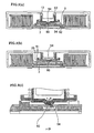
- FIG. 2 illustrates a cartridge in cross sections to show, by way of reference, a brake release mechanism before incorporating the structure according to the invention, (a) when the cartridge is not in use and (b) when it is loaded in a recorder.
- teeth 35 formed on the inner surface of hub 32 are engaged with teeth 51 of brake lock.
- a follower projection 52 of brake lock 5 fits on a projection 13 formed in upper casing 1 to hold brake lock 5 from turning.
- a brake release plate 9 which is in contact with a center lug 53 of brake lock 5 and is thereby urged downward.
- Brake release plate 9 has a plurality of (e.g., three) equidistantly spaced legs 92 fitted in small holes 34 correspondingly formed in hub 32. The ends of legs 92 extend beyond hub 32 but not beyond the outer surface of lower casing 2.
- tape reel 3 (with the aid of magnetic metal disk 7) is sucked up by a drive shaft of the recorder from the state shown in FIG. 2(a).
- the drive shaft pushes legs 92 upwardly with a concomitant lift of brake lock 5, disengaging its teeth 51 from teeth 35 of hub 32 and setting tape reel 3 free to turn.
- Legs 92 of brake release plate 9 remain fitted in holes 34 of hub 32, and the brake release plate turns together with tape reel 3 (as in FIG. 2(b)).
- Center lug 53 of brake lock 5 and brake release plate 9 are simply in contact, and looseness of engagement between the upper casing and brake lock or between brake lock and hub can sometimes bring the center of brake lock 5 out of alignment with that of brake release plate 9. In that case brake lock 5 upon its release might fail to press the center of tape reel 3 exactly enough to turn it stably.
- a lug 54 is formed in the center of brake lock 5 and a dent 93 in the center of the main plate 91 of brake release plate 9.
- the alignment is made more certain by forming a dent 93 with a radius of curvature R greater than the radius r of the convex surface of lug 54.
- FIG. 4 illustrates reversal of the concavo-convex relationship.
- Lug 54 of the first embodiment is replaced by a dent 55 and dent 93 replaced by a lug 94, and a similar favorable effect is achieved.
- Dent 55 with a radius of curvature R greater than the radius 5 of the head of lug 94 enhances the alignment.
- FIG. 7 is an exploded view of a tape cartridge as another embodiment of the invention.
- the cartridge comprises a housing consisting of upper and lower casings 1, 2 and a single tape reel 3 on which a length of tape is wound and which is turnably contained in the housing.
- Lower casing 2 has an opening 21 through which a drive shaft of a recorder is inserted into the housing.
- Upper and lower casings 1, 2 have cutouts 12, 22, respectively, which are joined to form an opening through which tape is to be pulled out.
- Tape reel 3 consists of an upper flange 31, a hub 32 formed in one piece with a lower flange 33, and a metal disk 7 that fits integrally to the underside of hub 32.
- Metal disk 7 has drive teeth 39 (FIG. 8(b)) formed along its periphery and adapted to engage a drive shaft of a recorder, whereby the disk is magnetically attracted to turn tape reel 3. There is no member to fix the tape in place, because the tape is directly affixed to the outer periphery of the hub with water or the like.
- Hub 32 has teeth 35 formed on its inner surface to be in mesh with a brake lock 5 to prevent unwanted turning of tape reel 3 when the latter is not in use.
- brake lock 5 has teeth 51 formed on its underside in mesh with the teeth 35 of hub 32. Brake lock 5 is normally urged in the braking position by brake spring 4. Brake lock 5 is not turnable but can be positively moved up and down between the braking position and brake release position as its follower projection 52 with a recess of an irregular shape slides in engagement with a positioning projection (indicated at 13 in FIG. 11) formed on the inner surface of upper casing 1.
- a brake release plate 9 is interposed between hub 32 and brake lock 5.
- Brake release plate 9 consists of a main plate 91 and a plurality of legs 92. Legs 92 fit in small throughholes 36 formed in the under surface of hub 32.
- FIG. 8 shows hub 32 in perspective.
- the lower surface of hub 32 has teeth 35 formed in portions away from throughholes 36, to be in mesh with brake lock 5.
- a dent 38 In the center of the hub is formed a dent 38, which is connected with the throughholes with radial grooves 37.
- drive teeth 39 adapted to engage a corresponding part of a recorder, and in the center is formed a projection 40 to fit in a center hole 71 of metal disk 7.
- leader block 18 is gripped at its engaging recess 19 by a draw-out member of the recorder. It is thus pulled out, led along a tape path to a take-up reel inside the recorder and is eventually held in a recess formed on the outer periphery of the take-up reel.
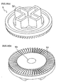
- FIG. 9 illustrates brake lock 5 in perspective, (a) as seen from above and (b) from below.
- Brake lock 5 has brake teeth 51 formed on the underside and adapted to engage teeth 35 of hub 32 so as to prevent unwanted turning of tape reel 3 and also has a lug 53 formed in the center which comes in contact with a brake release plate 9.
- FIG. 10 shows brake release plate 9 in perspective, (a) as seen from above and (b) from below.
- Brake release plate 9 consists of three legs 92 and a generally triangular main plate 91.
- a dent 93 is formed in the center of main plate 91. Dent 93 is located where it comes in contact with lug 53 of brake lock 5, and its concavity helps prevent off-center alignment of the two parts and ensure smooth turning of the reel.
- a sheet member 28 of highly slippery material is affixed to dent 93.
- Legs 92 extend into throughholes 36 and beyond the underside of hub 32. Reinforcing ribs 94 fit in grooves 37 of hub 32.
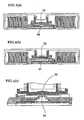
- FIG. 11 gives sectional views of the cartridge.
- brake release plate 9 is constantly urged downward from above by brake lock 5.
- legs 92 are forced upward as in FIG. 11(b), against the downward urging, by a brake release member (not shown) of a recorder, with consequent upward movement of brake release plate 9 and application of reversely directed forces to the center and legs 92 on the outer edges of brake release plate 9.
- first reinforcing ribs 94' are provided to add strength to brake release plate 9 as in FIG. 10(b).
- Suitable material for slippery sheet member 28 is Teflon sheet or ultra-high-molecular-weight polyethylene sheet. Sheet member 28 is affixed to brake release plate 9 with adhesive.
- sheet member 28 is affixed to brake release plate 9 in the illustrated embodiment, the sheet may be affixed to lug 53 of brake lock 5 instead. It is further possible to reverse the concavo-convex relationship of lug 53 of brake lock 5 and dent 93 of brake release plate 9.
- the interposition of a highly slippery sheet member according to the invention improves the sliding contact between the brake lock and brake release plate and permits the tape reel to turn stably.
- the center of rotation can be properly maintained and more smooth turning of the tape reel is ensured.
Landscapes
- Packaging Of Annular Or Rod-Shaped Articles, Wearing Apparel, Cassettes, Or The Like (AREA)
- Braking Arrangements (AREA)
Claims (3)
- Cassette de bande dans laquelle une seule bobine (3) de bande sur laquelle une longueur de bande (14) est enroulée est maintenue rotative à l'intérieur d'un boîtier constitué d'un cache supérieur (1) et d'un cache inférieur (2), le cache inférieur comportant une ouverture (21) à travers laquelle un axe d'entraînement d'un enregistreur doit être introduit, ladite bobine de bande comportant un moyeu (32) qui est ouvert au niveau supérieur et qui est fermé au niveau inférieur par une paroi, la paroi intérieure inférieure dudit moyeu comportant des trous (34) pour un engagement avec une plaque (9) de libération de frein, un disque métallique (7) est assujetti à la surface extérieure du côté inférieur dudit moyeu et des dents (39) sont formées sur la surface extérieure autour dudit disque métallique pour un engagement avec l'axe d'entraînement d'un enregistreur, des dents (35) servant à engager un verrou (5) de frein sont formées sur la surface intérieure inférieure dudit moyeu, ladite plaque (9) de libération de frein étant montée dans ledit moyeu à l'aide de jambes (92) introduites dans dés trous de ce dernier, ledit verrou de frein reposant sur ladite plaque de libération de frein, ledit verrou de frein comportant des dents (51) de frein formées sur la périphérie du côté inférieur de façon à s'engrener avec les dents dudit moyeu et comportant une saillie suiveuse (52) sur la surface supérieure, qui est conçue pour être guidée par une saillie (13) de guidage formée dans le cache supérieur pour pouvoir bouger vers le haut et vers le bas mais sans pouvoir tourner, et un élément (4) à ressort est disposé entre ledit verrou de frein et ledit cache supérieur pour solliciter ledit verrou de frein dans la position de freinage, caractérisée en ce que
un élément (28) sous forme de feuille très glissant est interposé entre les parties de contact dudit verrou (5) de frein et ladite plaque (9) de libération de frein. - Cassette de bande selon la revendication 1, caractérisée en ce que ledit verrou (5) de frein est formé avec un bossage (55) (ou un ergot (54)), une extrémité sphérique se trouvant au centre de son côté inférieur, et ladite plaque (9) de libération de frein est formée avec un ergot correspondant (94) (ou un bossage (93)), une extrémité sphérique se trouvant sur sa surface supérieure.
- Cassette de bande selon la revendication 2,
caractérisée en ce que le rayon de courbure R dudit bossage (55 ; 93) est plus grand que le rayon de courbure r dudit ergot (94 ; 54).
Applications Claiming Priority (4)
| Application Number | Priority Date | Filing Date | Title |
|---|---|---|---|
| JP11141538A JP2000331454A (ja) | 1999-05-21 | 1999-05-21 | テープカートリッジ |
| JP14153899 | 1999-05-21 | ||
| JP14461599 | 1999-05-25 | ||
| JP11144615A JP2000339909A (ja) | 1999-05-25 | 1999-05-25 | テープカートリッジ |
Publications (2)
| Publication Number | Publication Date |
|---|---|
| EP1054403A1 EP1054403A1 (fr) | 2000-11-22 |
| EP1054403B1 true EP1054403B1 (fr) | 2006-06-21 |
Family
ID=26473767
Family Applications (1)
| Application Number | Title | Priority Date | Filing Date |
|---|---|---|---|
| EP00109554A Expired - Lifetime EP1054403B1 (fr) | 1999-05-21 | 2000-05-04 | Cassette à bande |
Country Status (3)
| Country | Link |
|---|---|
| US (1) | US6452748B1 (fr) |
| EP (1) | EP1054403B1 (fr) |
| DE (1) | DE60028866T2 (fr) |
Families Citing this family (26)
| Publication number | Priority date | Publication date | Assignee | Title |
|---|---|---|---|---|
| US6680818B1 (en) * | 1998-06-08 | 2004-01-20 | Fuji Photo Film Co., Ltd. | Magnetic tape cartridge for housing a reel |
| DE19930802A1 (de) * | 1999-07-03 | 2001-01-04 | Emtec Magnetics Gmbh | Magnetbandkassette, insbesondere eine Einspulenkassette für die Datenverarbeitung mit mehrteiligem Bremssystem |
| CN1221974C (zh) * | 1999-07-09 | 2005-10-05 | 富士胶片株式会社 | 盒式磁带 |
| CN1179359C (zh) * | 1999-11-08 | 2004-12-08 | 富士胶片株式会社 | 磁带卡盘 |
| EP1146520B1 (fr) | 2000-04-05 | 2007-06-20 | FUJIFILM Corporation | Cassette à bande magnétique |
| US6865047B2 (en) * | 2000-11-02 | 2005-03-08 | Sony Corporation | Single reel tape cartridge and recording and reproducing device using the tape cartridge |
| DE20021132U1 (de) * | 2000-12-13 | 2001-04-19 | EMTEC Magnetics GmbH, 67059 Ludwigshafen | Transportsicherungselement für Datenspeicherkassetten, Datenspeicherkassettenstapel mit Transportsicherungselementen |
| JP2003085930A (ja) * | 2001-05-29 | 2003-03-20 | Fuji Photo Film Co Ltd | 磁気テープカートリッジ |
| JP2003109354A (ja) * | 2001-06-25 | 2003-04-11 | Fuji Photo Film Co Ltd | 磁気テープカートリッジ |
| JP2003091963A (ja) * | 2001-06-28 | 2003-03-28 | Fuji Photo Film Co Ltd | 記録テープカートリッジ |
| JP3522238B2 (ja) * | 2001-06-29 | 2004-04-26 | Necパーソナルプロダクツ株式会社 | カートリッジ嵌合機構 |
| JP2003187548A (ja) * | 2001-12-19 | 2003-07-04 | Hitachi Maxell Ltd | 単リール型の磁気テープカートリッジ |
| JP2004199773A (ja) * | 2002-12-18 | 2004-07-15 | Fuji Photo Film Co Ltd | 記録テープカートリッジ |
| JP4119786B2 (ja) * | 2003-05-21 | 2008-07-16 | 富士フイルム株式会社 | 記録テープカートリッジ |
| JP2005056486A (ja) * | 2003-08-01 | 2005-03-03 | Fuji Photo Film Co Ltd | 磁気テープカートリッジ |
| US6929207B2 (en) * | 2003-11-03 | 2005-08-16 | Hewlett-Packard Development Company, L.P. | Tape cartridge |
| US7066421B2 (en) * | 2003-12-10 | 2006-06-27 | Fuji Photo Film Co., Ltd. | Recording tape cartridge |
| US7290734B2 (en) * | 2003-12-22 | 2007-11-06 | Tdk Corporation | Tape reel and information recording medium |
| US7204444B2 (en) * | 2004-12-15 | 2007-04-17 | Quantum Corporation | Media cartridge having reel suspension system and method of manufacture |
| US20070200019A1 (en) * | 2006-02-27 | 2007-08-30 | Tdk Corporation | Chucking plate, tape reel, cartridge case, and information recording medium |
| JP2009076160A (ja) * | 2007-09-21 | 2009-04-09 | Sony Corp | 磁気テープカートリッジ |
| JP5868902B2 (ja) * | 2013-06-19 | 2016-02-24 | 富士フイルム株式会社 | 記録テープカートリッジ及びそれに設けられる制動部材 |
| JP6153910B2 (ja) * | 2014-09-19 | 2017-06-28 | 富士フイルム株式会社 | 金属プレート及び記録テープカートリッジ |
| US10442648B2 (en) * | 2017-05-24 | 2019-10-15 | Sandar Industries, Inc. | Dispenser apparatus and method of use for laminating and dispensing transfer tape in a paper web turn-up system |
| US10384900B2 (en) * | 2017-05-24 | 2019-08-20 | Sandar Industries, Inc. | Dispenser apparatus and method of use for laminating and dispensing transfer tape in a paper web turn-up system |
| WO2020129599A1 (fr) * | 2018-12-19 | 2020-06-25 | ソニー株式会社 | Cartouche de bande |
Family Cites Families (13)
| Publication number | Priority date | Publication date | Assignee | Title |
|---|---|---|---|---|
| JPS4952510U (fr) | 1972-08-11 | 1974-05-09 | ||
| CH663679A5 (fr) * | 1985-08-14 | 1987-12-31 | Gefitec Sa | Bobine en matiere plastique pour bande magnetique, prisonniere d'un boitier de cassette. |
| JPH0514379Y2 (fr) * | 1986-12-05 | 1993-04-16 | ||
| EP0284687A3 (fr) | 1987-03-31 | 1990-02-07 | Shape Inc. | Cassette à bande |
| US5027249A (en) * | 1989-11-09 | 1991-06-25 | Michael W. Johnson | Tape cartridge bearing |
| US5366173A (en) | 1993-03-01 | 1994-11-22 | Storage Technology Corporation | Tape cartridge reel brake release technique |
| EP0927421B1 (fr) | 1997-04-03 | 2003-07-02 | Koninklijke Philips Electronics N.V. | Cassette avec au moins une bobine a deplacement axial et avec un systeme de blocage pouvant empecher ledit deplacement axial de la bobine |
| JP3517729B2 (ja) * | 1997-06-13 | 2004-04-12 | 日立マクセル株式会社 | 単リール型の磁気テープカートリッジ |
| US6113020A (en) * | 1997-07-02 | 2000-09-05 | Seagate Technology, Inc. | Reel lock and coupling engagement mechanisms for a cartridge |
| JP3614634B2 (ja) | 1997-12-25 | 2005-01-26 | 富士写真フイルム株式会社 | 磁気テープカートリッジ |
| JP3884761B2 (ja) * | 1998-02-20 | 2007-02-21 | 日立マクセル株式会社 | 単リール型の磁気テープカートリッジ |
| US5901916A (en) | 1998-03-02 | 1999-05-11 | Hewlett-Packard Company | Tape cartridge reel lock |
| JP2001035126A (ja) * | 1999-07-26 | 2001-02-09 | Tdk Corp | テープカートリッジ |
-
2000
- 2000-05-01 US US09/562,341 patent/US6452748B1/en not_active Expired - Fee Related
- 2000-05-04 DE DE60028866T patent/DE60028866T2/de not_active Expired - Lifetime
- 2000-05-04 EP EP00109554A patent/EP1054403B1/fr not_active Expired - Lifetime
Also Published As
| Publication number | Publication date |
|---|---|
| DE60028866D1 (de) | 2006-08-03 |
| US6452748B1 (en) | 2002-09-17 |
| EP1054403A1 (fr) | 2000-11-22 |
| DE60028866T2 (de) | 2006-11-30 |
Similar Documents
| Publication | Publication Date | Title |
|---|---|---|
| US6452748B1 (en) | Tape cartridge with matched brake lock and brake release plate | |
| US6411466B1 (en) | Tape cartridge | |
| JP3755633B2 (ja) | 磁気テープカートリッジ | |
| US6264126B1 (en) | Tape cartridge | |
| US7085101B1 (en) | Magnetic tape cartridge with rotatably-mounted multi-projection brake release member | |
| CA1319192C (fr) | Cassette de bande magnetique et appareil d'enregistrement - lecture connexe muni d'une agrafe | |
| JPS6215906Y2 (fr) | ||
| JPH067507Y2 (ja) | ディスクカートリッジ | |
| JPS60229284A (ja) | 記録再生用デイスクカセツト | |
| JP4424897B2 (ja) | 記録テープカートリッジ | |
| US4184184A (en) | Cartridge with improved access door closing means | |
| US6886765B2 (en) | Single-reel magnetic tape cartridge | |
| US4635879A (en) | Tape cassette | |
| KR900018997A (ko) | 비데오 카세트용 탑로드 테이프 카트리지 | |
| JP4133666B2 (ja) | 記録テープカートリッジ | |
| JP4153275B2 (ja) | 記録テープカートリッジ | |
| JP2000339909A (ja) | テープカートリッジ | |
| JP4903305B2 (ja) | テープカートリッジ | |
| JP2000339910A (ja) | テープカートリッジ | |
| JP2001035127A (ja) | テープカートリッジ | |
| US4985798A (en) | Magnetic tape cassette having improved dust proofing | |
| JPS633032Y2 (fr) | ||
| JP2000331454A (ja) | テープカートリッジ | |
| KR0140883B1 (ko) | 자기 디스크의 센터코어 | |
| JPH0728631Y2 (ja) | 磁気テープカセット |
Legal Events
| Date | Code | Title | Description |
|---|---|---|---|
| PUAI | Public reference made under article 153(3) epc to a published international application that has entered the european phase |
Free format text: ORIGINAL CODE: 0009012 |
|
| AK | Designated contracting states |
Kind code of ref document: A1 Designated state(s): DE GB |
|
| AX | Request for extension of the european patent |
Free format text: AL;LT;LV;MK;RO;SI |
|
| 17P | Request for examination filed |
Effective date: 20010516 |
|
| AKX | Designation fees paid |
Free format text: DE GB |
|
| 17Q | First examination report despatched |
Effective date: 20050512 |
|
| GRAP | Despatch of communication of intention to grant a patent |
Free format text: ORIGINAL CODE: EPIDOSNIGR1 |
|
| GRAS | Grant fee paid |
Free format text: ORIGINAL CODE: EPIDOSNIGR3 |
|
| GRAA | (expected) grant |
Free format text: ORIGINAL CODE: 0009210 |
|
| AK | Designated contracting states |
Kind code of ref document: B1 Designated state(s): DE GB |
|
| REG | Reference to a national code |
Ref country code: GB Ref legal event code: FG4D |
|
| REF | Corresponds to: |
Ref document number: 60028866 Country of ref document: DE Date of ref document: 20060803 Kind code of ref document: P |
|
| PLBE | No opposition filed within time limit |
Free format text: ORIGINAL CODE: 0009261 |
|
| STAA | Information on the status of an ep patent application or granted ep patent |
Free format text: STATUS: NO OPPOSITION FILED WITHIN TIME LIMIT |
|
| 26N | No opposition filed |
Effective date: 20070322 |
|
| PGFP | Annual fee paid to national office [announced via postgrant information from national office to epo] |
Ref country code: DE Payment date: 20120502 Year of fee payment: 13 |
|
| PGFP | Annual fee paid to national office [announced via postgrant information from national office to epo] |
Ref country code: GB Payment date: 20120502 Year of fee payment: 13 |
|
| GBPC | Gb: european patent ceased through non-payment of renewal fee |
Effective date: 20130504 |
|
| PG25 | Lapsed in a contracting state [announced via postgrant information from national office to epo] |
Ref country code: DE Free format text: LAPSE BECAUSE OF NON-PAYMENT OF DUE FEES Effective date: 20131203 |
|
| REG | Reference to a national code |
Ref country code: DE Ref legal event code: R119 Ref document number: 60028866 Country of ref document: DE Effective date: 20131203 |
|
| PG25 | Lapsed in a contracting state [announced via postgrant information from national office to epo] |
Ref country code: GB Free format text: LAPSE BECAUSE OF NON-PAYMENT OF DUE FEES Effective date: 20130504 |