EP1054540A2 - Verfahren, Vorrichtung und Empfänger zur Erkennung der Lage des Nullsymbols - Google Patents
Verfahren, Vorrichtung und Empfänger zur Erkennung der Lage des Nullsymbols Download PDFInfo
- Publication number
- EP1054540A2 EP1054540A2 EP00303528A EP00303528A EP1054540A2 EP 1054540 A2 EP1054540 A2 EP 1054540A2 EP 00303528 A EP00303528 A EP 00303528A EP 00303528 A EP00303528 A EP 00303528A EP 1054540 A2 EP1054540 A2 EP 1054540A2
- Authority
- EP
- European Patent Office
- Prior art keywords
- period
- null symbol
- circuit
- correlation value
- signal
- Prior art date
- Legal status (The legal status is an assumption and is not a legal conclusion. Google has not performed a legal analysis and makes no representation as to the accuracy of the status listed.)
- Withdrawn
Links
Images



Classifications
-
- H—ELECTRICITY
- H04—ELECTRIC COMMUNICATION TECHNIQUE
- H04B—TRANSMISSION
- H04B1/00—Details of transmission systems, not covered by a single one of groups H04B3/00 - H04B13/00; Details of transmission systems not characterised by the medium used for transmission
- H04B1/06—Receivers
- H04B1/16—Circuits
-
- H—ELECTRICITY
- H04—ELECTRIC COMMUNICATION TECHNIQUE
- H04L—TRANSMISSION OF DIGITAL INFORMATION, e.g. TELEGRAPHIC COMMUNICATION
- H04L27/00—Modulated-carrier systems
- H04L27/26—Systems using multi-frequency codes
- H04L27/2601—Multicarrier modulation systems
- H04L27/2647—Arrangements specific to the receiver only
- H04L27/2655—Synchronisation arrangements
- H04L27/2656—Frame synchronisation, e.g. packet synchronisation, time division duplex [TDD] switching point detection or subframe synchronisation
-
- H—ELECTRICITY
- H04—ELECTRIC COMMUNICATION TECHNIQUE
- H04L—TRANSMISSION OF DIGITAL INFORMATION, e.g. TELEGRAPHIC COMMUNICATION
- H04L27/00—Modulated-carrier systems
- H04L27/26—Systems using multi-frequency codes
- H04L27/2601—Multicarrier modulation systems
- H04L27/2647—Arrangements specific to the receiver only
- H04L27/2655—Synchronisation arrangements
- H04L27/2662—Symbol synchronisation
-
- H—ELECTRICITY
- H04—ELECTRIC COMMUNICATION TECHNIQUE
- H04L—TRANSMISSION OF DIGITAL INFORMATION, e.g. TELEGRAPHIC COMMUNICATION
- H04L27/00—Modulated-carrier systems
- H04L27/26—Systems using multi-frequency codes
- H04L27/2601—Multicarrier modulation systems
- H04L27/2647—Arrangements specific to the receiver only
- H04L27/2655—Synchronisation arrangements
- H04L27/2666—Acquisition of further OFDM parameters, e.g. bandwidth, subcarrier spacing, or guard interval length
-
- H—ELECTRICITY
- H04—ELECTRIC COMMUNICATION TECHNIQUE
- H04L—TRANSMISSION OF DIGITAL INFORMATION, e.g. TELEGRAPHIC COMMUNICATION
- H04L27/00—Modulated-carrier systems
- H04L27/26—Systems using multi-frequency codes
- H04L27/2601—Multicarrier modulation systems
- H04L27/2647—Arrangements specific to the receiver only
- H04L27/2655—Synchronisation arrangements
- H04L27/2668—Details of algorithms
- H04L27/2673—Details of algorithms characterised by synchronisation parameters
- H04L27/2676—Blind, i.e. without using known symbols
-
- H—ELECTRICITY
- H04—ELECTRIC COMMUNICATION TECHNIQUE
- H04L—TRANSMISSION OF DIGITAL INFORMATION, e.g. TELEGRAPHIC COMMUNICATION
- H04L1/00—Arrangements for detecting or preventing errors in the information received
- H04L1/004—Arrangements for detecting or preventing errors in the information received by using forward error control
- H04L1/0045—Arrangements at the receiver end
- H04L1/0054—Maximum-likelihood or sequential decoding, e.g. Viterbi, Fano, ZJ algorithms
Definitions
- the present invention generally relates to a null symbol position detecting method and a null symbol position detecting apparatus for detecting a null symbol from signals such as DAB (Digital Audio Broadcast) signal for example and to a receiver for receiving such a signal including null symbols.
- DAB Digital Audio Broadcast
- DAB digital audio broadcast services of the European standard (Eureka 147) called DAB.
- DAB transmits a broadcast signal (or an ensemble signal) formed by multiplexing audio data of plural broadcast programs, various control information, and additional information.
- the audio data are encoded highly efficiently (data-compressed) by an international standard MPEG audio scheme to be transmission-line encoded by use of error-correction convolutional coding for example.
- the bit streams of the encoded audio data and information are interleaved and modulated by OFDM (Orthogonal Frequency Division Multiplex) before being transmitted.
- OFDM Orthogonal Frequency Division Multiplex
- This DAB broadcast signal has a frame structure as shown in FIG. 5. Namely, each frame consists of a synchronization channel, an FIC (Fast Information channel), and an MSC (Main service Channel).
- FIC Fast Information channel
- MSC Main Service Channel
- a null symbol indicates the start position of each frame.
- a TII Transmitter Identification Information
- the null symbol has no information to be transmitted as data.
- a synchronization symbol that follows the null symbol provides synchronization information for obtaining frequency offset and time offset in the receiver.
- FIC block 1 through block 3
- these FIC blocks convey an array of multiplexed broadcast programs, labels such as broadcast station name (ensemble label) and program name (program label), and information indicative of broadcast program type.
- the MSC has data fields (transmission symbols) of plural multiplexed broadcast programs as shown in FIG. 5. Namely, plural pieces of audio data multiplexed on a DAB signal are the MSC data fields. Each of the MSC data fields consists of a guard band (or a guard interval) and a valid symbol as shown in FIG. 5.
- each guard band period is made equal to a part of the period of each valid symbol, for example, the information of a period indicated by period DK at the end of each valid symbol as shown in FIG. 5.
- This guard band significantly improves the quality of reception of a DAB signal on a moving vehicle like an automobile in such highly radio-reflective environments as urban and hilly districts, as compared with other modulation schemes. Namely, as long as a time difference between the first and last reflected waves does not exceed the guard band period, no inter-symbol interference takes place and there is no need for waveform equalization.
- a DAB receiver uses the above-mentioned FIC-included information for broadcast program identification and the information about the multiplexing to extract and reproduce a user-specified broadcast program from the DAB signal multiplexed with plural broadcast programs, allowing the user to listen to audio broadcast of high sound quality.
- each DAB signal frame In order to receive the above-mentioned DAB signal to tune in to a desired broadcast program, the beginning of each DAB signal frame must be identified to accurately extract the information that follows the synchronization symbol. Therefore, null symbol detection is executed in the receiver.
- a null symbol position is detected by analog signal processing. Namely, when a DAB signal is received and envelope-detected, the level of the envelope waveform becomes low in the null symbol portion. Therefore, by comparing the envelope waveform with a reference voltage, a null detection signal can be generated.
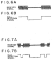
- FIG. 6A shows a waveform of a received DAB signal, in which the low-level portion indicates the null symbol portion.
- a null detection signal is formed in which it goes low during the period of the null symbol and high in the other portions as shown in FIG. 6B.
- the reference signal is set improperly or if a DAB signal is received on a moving vehicle on which an unwanted phenomenon such as fading takes place, the received signal is disturbed, resulting in poor reception of the DAB signal or causing a null detection signal to occur at positions where it should not.
- the envelope of the received signal becomes broad and narrow as shown in FIG. 7A. Namely, the envelope of the received signal becomes narrow in other portions than the null symbol period.
- null detection signal becomes low indicative of the detection of a null symbol also at positions other than where it should be present, thereby causing null symbol erroneous detection, thereby failing quick and correct null symbol detection.
- a null symbol position detecting method for receiving a signal and detecting a null symbol position from the received signal, in the signal of which a unit transmission frame has at least a null symbol at the beginning of the unit transmission frame and a plurality of transmission symbols following the null symbol, each of the plurality of transmission symbols having a guard band and a valid symbol, information included in a period of the guard band is made equal to information included in the valid symbol at an end thereof, and a length of a period of the null symbol is made different from a length or a period of each of the plurality of transmission symbols, the method comprising the steps of computing a correlation value between the received signal and a signal obtained by delaying the received signal by a length of a period of the valid symbol, and detecting the null symbol position on the basis of a variation in a period in which the correlation value is computed above a predetermined level.
- a signal multiplexed with a null symbol and one or more transmission symbols in a time division manner is received.
- a correlation value between the received signal and a signal obtained by delaying the received signal by one valid symbol period is computed. Because of the length of null symbol period is different from the length of transmission symbol period, the period in which a correlation value higher than a certain level is computed varies even within a unit transmission section (or a frame). A null symbol position is detected on the basis of this variation.
- a null symbol position is detected on the basis of the variation in the period in which a correlation value higher than a certain level is computed. This permits the quick and accurate detection of null symbol position without being affected by the variation in the reception level of a received signal due to fading for example, always ensuring the quick and accurate null symbol position detection.
- a null symbol position detecting method wherein a moving average for a period equal to the period of the guard band is computed for the correlation value between the received signal and a signal obtained by delaying the received signal by a length of a period of the valid symbol and the null symbol position is detected on the basis of a variation in a period in which the computed moving average peaks.
- a correlation value between the received signal and a signal obtained by delaying the received signal by one valid symbol period is computed. Because of the length of null symbol period is different from the length of transmission symbol period, the correlation value occurrence pattern varies within the unit transmission section in time or in correlation value level. The null symbol position is detected on the basis of this correlation value occurrence pattern.
- a null symbol position is detected on the basis or correlation value occurrence pattern. This permits the quick and accurate detection of null symbol position without being affected by the variation in the reception level of a received signal due to fading for example, always ensuring the quick and accurate null symbol position detection.
- null symbol position detecting method wherein the null symbol position is detected on the basis of a time interval in which the moving average peaks.
- the information of guard band period is made equal to the information of a portion (end portion) at the end of a valid symbol following that guard band, the portion (period) having the same length as the guard band period.
- a moving average is computed for a period equal to the guard band period. Consequently, the value of the moving average of the correlation value is peaked at the end of each transmission symbol (namely, in the boundary between transmission symbols).
- a peak-to-peak period of moving average correctly matches the transmission symbol period but, in the null symbol period, the peak level goes low. Therefore, the peak variation period and the peak occurrence pattern vary regularly, comparatively facilitating null symbol detection.
- the null symbol position in the received signal can be quickly and accurately detected by use of the peak of the moving average of the correlation value as a correlation value and on the basis of the variation in the period of this peak or on the basis of the peak occurrence pattern.
- a null symbol position detecting method for receiving a signal and detecting a null symbol position from the received signal, in the signal of which a unit transmission frame has at least a null symbol at the beginning of the unit transmission frame and a plurality of transmission symbols following the null symbol, each of the plurality of transmission symbols having a guard band and a valid symbol, information included in a period of the guard band is made equal to information included in the valid symbol at an end thereof, and a length of a period of the null symbol is made different from a length of a period of each of the plurality of transmission symbols, the method comprising the steps of computing a correlation value between the received signal and a signal obtained by delaying the received signal by a length of a period of the valid symbol, computing, for the correlation value, a moving average for a period equal to the period of the guard band to detect peaking of the moving average, and detecting the null symbol position on the basis of an occurrence pattern in which the moving average
- the information of guard band period is made equal to the information of a portion (end portion) at the end of a valid symbol following that guard band, the portion (period) having the same length as the guard band period.
- a moving average is computed for a period equal to the guard band period. Consequently, the value of the moving average of the correlation value is peaked at the end of each transmission symbol (namely, in the boundary between transmission symbols).
- a peak-to-peak period of moving average correctly matches the transmission symbol period but, in the null symbol period, the peak level goes low.
- the reception of the null symbol is detected on the basis of the occurrence pattern of the moving average peak.
- the peak-to-peak time interval is obtained. It is determined whether this time interval includes the null symbol period, thereby accurately detecting the null symbol position in the received signal.
- the use of the moving average peak of the correlation value between received signals allows the detection of null symbol position without being affected by the reception level of the received signal. And the use of the peak-to-peak time interval allows the accurate detection of null symbol position without involving erroneous detection.
- DAB has several modes. In the embodiment to be described below, DAB signals of mode 1 are used for example. Mode 1 is used for a Single Frequency Network. In this mode, length Tf of a unit transmission section (or a frame) is 96 ms, symbol length Ts is 1 ms, and guard band length Tg is 246 ⁇ s.
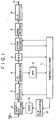
- FIG. 1 is a block diagram illustrating a DAB receiver of the above-mentioned preferred embodiment.
- the embodied receiver comprises an antenna 1, a front-end section (a receive and tune-in section) 2, an A/D converter 3, an I/Q demodulator 4, an automatic frequency controller (hereinafter referred to as AFC) 5, a Fast Fourier Transform section (hereinafter referred to as FFT) 6, a Viterbi decoder 7, an MPEG decoder 8, a D/A converter 9, an output terminal 10, a controller based on DSP (Digital Signal Processor) 11, a D/A converter 12, and a voltage-controlled crystal oscillator (hereinafter referred to as VCXO) 13.
- AFC automatic frequency controller
- FFT Fast Fourier Transform section
- MPEG decoder 8 an MPEG decoder 8
- D/A converter 9 an output terminal 10
- VCXO voltage-controlled crystal oscillator
- a DAB signal received at the antenna 1 is supplied to the front-end section 2.
- the front-end section 2 comprises a tuner and an intermediate frequency converter. On the basis of the oscillation frequency supplied from the VCXO 13 controlled by the controller 11, the front-end section 2 receives and tunes in to the DAB signal, converts the tuned-in broadcast signal into an intermediate frequency signal, and supplies it to the A/D converter 3.
- the A/D converter 3 converts the analog intermediate frequency signal into a digital signal and supplies it to the I/Q demodulator 4. From this digital intermediated frequency signal, the I/Q demodulator 4 demodulates signals of I-component and Q-component of a baseband signal and supplies them to the AFC 5 and the FFT 6.
- the FFT 6 OFDM-demodulates the I-component and Q-component signals supplied from the I/Q demodulator 4. Of the demodulated signals, a synchronization symbol (or a TFPR symbol) is supplied to the controller 11. The OFDM-demodulated FIC information and MSC information are supplied to the Viterbi decoder 7.
- the controller 11 obtains the frequency offset of the received and tuned-in DAB signal on the basis of the data obtained by the null symbol detection processing by the AFC 5 and the result of synchronization symbol frequency analysis from the FFT 6.
- the obtained frequency offset is converted by the D/A converter 12 into an analog signal, which is supplied to the VCXO 13.
- the oscillation frequency of the VCXO 13 is adjusted to correct the frequency offset of the DAB signal received and tuned in by the front-end section 2 and is supplied to the A/D converter 3.
- This frequency offset correction processing is performed as an initial operation. In this receiver, this processing is performed to receive a DAB signal or change tuned-in DAB signals.
- the DAB signal corrected in its frequency offset is supplied to the Viterbi decoder 7 through the I/Q demodulator 4 and the FFT 5.
- the Viterbi decoder 4 performs Viterbi decoding processing on the supplied DAB signal to restore the original DAB signal.
- the data of the FIC portion is supplied to the controller 11.
- a selection control signal according to the selection command given by the user of this receiver is supplied from the controller 11 to the Viterbi decoder 7.
- the audio data of the broadcast program specified by the selection control signal is extracted to be supplied to the MPEG decoder 8.
- the MPEG decoder 8 decompresses the MPEG-compressed audio data and supplies the decompressed audio data to the D/A converter 9.
- the D/A converter 9 converts the decompressed audio data into an analog signal, which is outputted through the output terminal 10.
- the audio signal is then supplied to a loudspeaker for example to be sounded as the broadcast program specified by the user.
- the detection of the null symbol position of a received and tuned-in DATA signal is not performed by use of the envelope waveform of the received signal. Rather, the null symbol position is detected by computing, in the AFC 5, the correlation value between the received and tuned-in DAB signal and a signal obtained by delaying this DAB signal by one valid symbol period.
- FIG. 2 is a block diagram illustrating the configuration of the above-mentioned AFC 5.
- the AFC 5 comprises an I-component delay circuit 51, a Q-component delay circuit 52, a correlation circuit 53, a moving average circuit 54, an absolute value circuit 55, a peak decision circuit 56, a peak time detection circuit 57, a symbol counter 58, a local time counter 59, a peak value temporary hold circuit 60, a peak time temporary hold circuit 61, a level pattern decision circuit 62, a time interval decision circuit 63, and a null decision circuit 64.
- the I-component and Q-component signals of the baseband signal are supplied from the I/Q demodulator 4 to the AFC 5.
- the I-component signal I and the Q-component signal Q are supplied to the correlation circuit 53.
- the I-component signal I is supplied to the I-component delay circuit 51 and the Q-component signal Q is supplied to the Q-component delay circuit 52.
- the I-component delay circuit 51 delays the supplied I-component signal I by one valid symbol period and supplies the resultant delay signal Id to the correlation circuit 53.
- the Q-component delay circuit 52 delays the supplied Q-component signal Q by one valid symbol period and supplies a resultant delay signal Qd to the correlation circuit 53.
- the correlation values (complex vectors) computed by the correlation circuit 53 are supplied to the moving average circuit 54.
- the moving average circuit 54 computes moving averages Ia and Qa for a period equal to guard band period and supplies the computed Ia and Qa to the absolute value circuit 55.
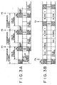
- FIGs. 3A and 3B illustrate an operation in which the moving averages of the correlation values Ir and Qr are peaked in the boundary of transmission symbols.
- the guard band period information is the same as the information of the period DK having the same length as the period of the guard band at the end of each valid symbol.
- a correlation value between the information of the period DK at the end of each valid symbol and the guard band period information is obtained by obtaining a correlation between the DAB signal and a signal obtained by delaying the DAB signal by one valid symbol period.
- guard band period information is the same as the information of the period DK of each valid symbol
- the value of the moving average of the correlation value is maximized in positions P1, P2, P3, and so on at the end of the transmission symbols (or in the boundary between the transmission symbols).
- the value of the moving average for the guard band of the correlation value is maximized, so that, in a period where transmission symbols Continue in a row, the moving average of the correlation value peaks every 1 ms which is the length of transmission symbol period.
- the level of correlation in the obtained correlation values is low because there is no transmission information to be transmitted as data as described above.
- the moving average of correlation value peaks every symbol period (every 1 ms), while the peak level of moving average is very low in null symbol portion.
- the period between moving average high-level peak occurrence position Pe of the correlation value immediately before a null symbol and next high-level peak occurrence position Ps is the period obtained by adding null symbol period and block 1 period. This indicates that the occurrence period of the high-level peak of correlation value moving average is different from the period in which transmission symbols continue in a row.
- the periods of symbols other than null symbol have a same length but the length of null symbol period is greater than those of other symbols by about several 10 ⁇ s.
- a moving average peak is obtained from the absolute value of moving average (complex vector) to detect the occurrence period of the peak as will be described, thereby detecting null symbol position.
- null symbol position is detected by use of vector phase difference information.
- the peak decision circuit 56 compares the absolute value S supplied last time and the absolute value S supplied this time and keeps the larger one in the peak decision circuit 56.
- the peak decision circuit 56 may also compare the absolute value S supplied from the absolute value circuit 55 with a preset threshold for example before comparing the previously supplied absolute value S with the newly supplied absolute value S, thereby regarding the absolute value S smaller than the threshold as no peak.
- the peak decision circuit 56 When an absolute value S has been supplied, the peak decision circuit 56 notifies the peak time detection circuit 57 thereof. Upon reception of this notification, the peak time detection circuit 57 detects time information (a count value) indicative of the occurrence point of the absolute value S from the local time counter 59 and holds the detected count value.
- the peak value temporary hold circuit 60 latches the absolute value S (the peak) held in the peak decision circuit 56.
- the peak rime temporary hold circuit 61 latches the time information (peak time) held in the peak time detection circuit 57.
- the symbol counter 58 generates one clock of timing signal every one symbol period of a DAB signal.
- the local time counter 59 performs count processing with a clock of about 1.5 ⁇ s for example, completing one cycle in one frame of a DAB signal.
- the receiver of the present embodiment receives a DAB signal of mode 1 as described above, so that the symbol counter 58 generates a clock signal of symbol unit time and the local time counter 59 performs count processing by a clock signal of 1.5 ⁇ s for example to complete one cycle in 96 ms.
- the peak value temporary hold circuit 60 latches the peak of the moving average of the correlation value that is maximized in the boundary between transmission symbols and the peak time temporary hold circuit 61 latches the peak time indicative of the occurrence time of the peak latched by the peak value temporary hold circuit 60.
- the peak value temporary hold circuit 60 supplies the peak supplied from the peak decision circuit 56 to the level pattern decision circuit 62.
- the peak time temporary bald circuit 61 supplies the peak time supplied from the peak time detection circuit 57 to the time interval decision circuit 63.
- the peak value temporary hold circuit 60 and the peak time temporary hold circuit 61 latch peak and peak time respectively in response to the timing signals supplied from the symbol counter 58, supply the latched information to the level pattern decision circuit 62 and the time interval decision circuit 63 respectively, and then clear the peak and the peak time upon receiving next timing signals supplied from the symbol counter 58.
- the level pattern decision circuit 62 is adapted to hold n (n being an integer of 2 or higher) peaks.
- the time interval decision circuit 63 can hold n peak times corresponding to n peaks held in the level pattern decision circuit 62.
- the level pattern decision circuit 62 can hold 3 peaks.
- the time interval decision circuit 63 can bold 3 peak times.
- the level pattern decision circuit 62 determines whether a null symbol has been received on the basis of the level pattern of the 3 peaks held in it. Namely, as described with reference to FIGs. 3A and 3B, during the period in which transmission symbols continue in a row, the peak of the moving average of correlation values is at high level and the peak takes place for every transmission symbol period. However, in a null symbol period, which is longer than a transmission symbol period, the peak of the moving average of correlation values is at low level. In this case, the interval between adjacent peaks of high level is broader.
- the time interval decision circuit 63 obtains the time interval between peaks.
- the time interval decision circuit 63 determines whether the length of the time interval between peaks including a null symbol matches the length in the case where the null symbol of the DAB signal in mode 1 is included. Consequently, the time interval decision circuit 63 can determine whether the interval found including a null symbol truly includes a null symbol.
- the information indicative of the decision results supplied from the level pattern decision circuit 62 and the time interval decision circuit 63 is supplied to the null decision circuit 64. Then, as described, if a null symbol is detected by the time interval decision circuit 64, the null decision circuit 64 obtains a local time of the final end of this frame on the basis of the peak supplied from the level pattern decision circuit 62 for every symbol period, the supply timing of this peak, or the peak time supplied from the time interval decision circuit 63. The null decision circuit 64 supplies the obtained local time to the local time counter 59 at the final end of this frame.
- the local time counter 59 resets the current count value and starts counting from "0" at the beginning of the null symbol of each frame of the received and tuned-in DAB signal.
- the null decision circuit 64 is adapted to supply a null symbol detection signal to the controller 11 of the present embodiment at the beginning of the null symbol.
- the AFC 5 of the present embodiment functions as a null symbol position detecting apparatus.
- the null symbol detecting circuit is composed of the level pattern decision circuit 62, the time interval decision circuit 63, and the null symbol decision circuit 64.
- the position of the null symbol of the received and tuned-in DAB signal namely the beginning of each frame, can be detected by digital processing.
- the null symbol detection processing to be performed by the level pattern decision circuit 62, the time interval decision circuit 63, and the null symbol decision circuit 64.
- the null symbol detection processing shown in FIG. 4 is executed immediately after the reception and tune-in of a DAB signal, after changing channels by the receiver of the present embodiment, or after a temporary signal drop and restoration therefrom in a very weak electromagnetic field environment such as inside a tunnel.
- the level pattern decision circuit 62 determines whether a new peak has been supplied from the peak value temporary hold circuit 60 (step S201). If no new peak is found supplied, the level pattern decision circuit 62 repeats the processing of step S201. If a new peak is found supplied, the level pattern decision circuit 62 compares levels of past n (for example, 3) peaks including the newly supplied peak held in the circuit 62 (step S202) to determine whether there is any low-level peak (step S203).
- n for example, 3
- the level pattern decision circuit 62 deletes the oldest of the n peaks held in it (step S207) and repeats the processing of step S201 and on.
- step S203 If, in step S203, one low-level peak is found by the level pattern decision circuit 62, namely the level pattern decision circuit 62 has determined it is highly possible that this period is a period including a null symbol, the time interval decision circuit 63 computes the time interval of the period between the peaks that includes the null symbol on the basis of the peak time corresponding to each peak (step S204).
- the time interval decision circuit 63 determines whether the computed peak-to-peak time interval matches the length of the period including the null symbol of the corresponding mode (step S205). Namely, if this period is a period that includes a null symbol, the peak-to-peak interval is a sum of the length of null symbol period and the length of transmission symbol (block 1 in FIG. 3B) period as described with reference to FIG. 3B. On the other hand, if it is a period in which transmission symbols continue in a row but only one of the peaks of correlation value moving average merely dropped for some reason, the length of the peak-to-peak period only becomes twice as high as the transmission symbol period.
- the length of the null symbol period can be computed by subtracting the length of the period for one transmission symbol from the length of the period between peaks Pe and Ps.
- the matching can be determined by comparing the computed length of null symbol period with the length of null symbol period of a target mode.
- the level pattern decision circuit 62 deletes the oldest of the n peaks held in it (step S207) and repeats the processing of step S201 and on.
- the null symbol decision circuit 64 obtains the local time at the final end of each DAB signal frame on the basis of the information supplied from the level pattern decision circuit 62 and the information such as the peak time supplied from the time interval decision circuit 63.
- the null decision circuit 64 sets the obtained local time to the local time counter 59 (step S206) at the final end of that frame.
- the local time counter 59 When the local time is supplied from the null decision circuit 64, the local time counter 59 is reset. Subsequently, the local time counter 59 starts always with "0" at the beginning of the null symbol of the received signal.
- the null decision circuit 64 supplies a null symbol detection signal at the beginning of each frame to the controller 11. This allows the controller 11 to correctly obtain the frequency offset of the received signal, thereby quickly and accurately correcting this frequency offset by controlling the VCXO13.
- the null symbol position of a received signal is detected by digital processing by considering the correlation of the received signals. Consequently, the null symbol position is always detected quickly and correctly without being affected by the reception level of a received DAB signal even if the reception level fluctuates due to fading or the like.
- the length of the period in which the possibility of null symbol inclusion is high is matched against the length of the period in which the null symbol of the broadcast signal of a target mode is included. This prevents a transmission symbol period in which a high-level peak is missing by chance from being mistakenly determined as a null symbol period.
- a correlation value between a received and tuned-in DAB signal and a signal obtained by delaying this DAB signal by one valid symbol period is obtained and the moving average for the same period as the length of the period of the guard band of this obtained correlation value, thereby causing the moving average to peak in the boundary between received symbols.
- the same purpose can also be attained without use of moving average.
- a high-level correlation value continuing for a period of the same length as the guard band is followed by the beginning of a next transmission symbol. Use of this information can identify the local time at the final end of that frame and set the local time at that final end to the local time counter 59, thereby resetting the same.
- null symbol reception is determined by a peak occurrence pattern. If a null symbol is found received, the time interval between peaks is computed to determine whether a null symbol has been truly received or not.
- the present invention is not limited to this configuration.
- the position of the received null symbol may be identified for null symbol detection.
- only the time interval between peaks adjacent in time may be monitored for the detection of null symbol position.
- a null symbol position may be detected on the basis of the information about the change in peak occurrence period or the information about peak occurrence pattern. Additional consideration of the time interval between peaks as the change in peak occurrence period can surely prevent the erroneous detection or null symbols.
- a null symbol position may be detected on the basis of the information about the change in peak occurrence period or the information about peak occurrence pattern.
- the above-mentioned receiver of the present embodiment has been described by use of an example in which a DAB signal of mode 1 is received.
- the DAB signals that can be received and tuned in by this receiver are not limited to the mode 1 signal. Namely, the receiver can also handle the DAB signals of mode 2 and mode 3 for example.
- the receiver can also be adapted to receive and process only the mode 1 DAB signal.
- the receiver can also be adapted to receive and tune in the broadcast signals of all modes such as mode 1, mode 2, and mode 3. In this case, a null symbol position is detected according to the mode of a received and tuned-in DAB signal by switching between the DAB signal modes according to the received and tuned-in broadcast signal or by the operator of this receiver.
- null symbol position detecting apparatus may be formed and installed on various receivers.
- the present invention is not only applicable to DAB signals.
- the present invention is also applicable to various types of digital audio broadcast signals and various terrestrial digital television signals having a null symbol, using OFDM, and having a guard band period.
- the present invention is applicable to not only broadcast signals but also various transmission signals on which null symbols and transmission symbols are multiplexed in a time division manner, each transmission symbol being composed of a guard band and a valid symbol, the information of the guard band being the same as the information about a part of the valid symbol.
- a null symbol position is detected by use of the correlation between received signals, thereby quickly and accurately detecting a null symbol position if the reception level of a received signal changes due to fading for example. Consequently, the novel configuration can quickly and accurately obtain the frequency offset of a received signal and quickly correct the obtained frequency offset to make the broadcast signal available always in a quick and good state.
- null symbol position is detected by digital processing. Consequently, unlike analog received signals, a null symbol can be quickly and accurately detected from a received signal without causing a delay in null symbol detection.
Landscapes
- Engineering & Computer Science (AREA)
- Computer Networks & Wireless Communication (AREA)
- Signal Processing (AREA)
- Circuits Of Receivers In General (AREA)
- Synchronisation In Digital Transmission Systems (AREA)
- Monitoring And Testing Of Transmission In General (AREA)
Applications Claiming Priority (2)
| Application Number | Priority Date | Filing Date | Title |
|---|---|---|---|
| JP12346599 | 1999-04-30 | ||
| JP12346599A JP4164609B2 (ja) | 1999-04-30 | 1999-04-30 | ヌルシンボル位置検出方法、ヌルシンボル位置検出装置および受信機 |
Publications (2)
| Publication Number | Publication Date |
|---|---|
| EP1054540A2 true EP1054540A2 (de) | 2000-11-22 |
| EP1054540A3 EP1054540A3 (de) | 2006-11-02 |
Family
ID=14861312
Family Applications (1)
| Application Number | Title | Priority Date | Filing Date |
|---|---|---|---|
| EP00303528A Withdrawn EP1054540A3 (de) | 1999-04-30 | 2000-04-27 | Verfahren, Vorrichtung und Empfänger zur Erkennung der Lage des Nullsymbols |
Country Status (5)
| Country | Link |
|---|---|
| US (1) | US6731702B1 (de) |
| EP (1) | EP1054540A3 (de) |
| JP (1) | JP4164609B2 (de) |
| KR (1) | KR100650744B1 (de) |
| CN (1) | CN1299452C (de) |
Cited By (2)
| Publication number | Priority date | Publication date | Assignee | Title |
|---|---|---|---|---|
| WO2004054144A1 (en) * | 2002-12-10 | 2004-06-24 | Matsushita Electric Industrial Co., Ltd. | Null symbol detection device |
| EP2259523A3 (de) * | 2009-06-04 | 2012-02-08 | Sony Corporation | Empfangsvorrichtung, Empfangsverfahren und Programm und Empfangssystem |
Families Citing this family (17)
| Publication number | Priority date | Publication date | Assignee | Title |
|---|---|---|---|---|
| GB2353680A (en) * | 1999-08-27 | 2001-02-28 | Mitsubishi Electric Inf Tech | OFDM frame synchronisation |
| KR100333818B1 (ko) * | 2000-08-16 | 2002-04-26 | 윤종용 | 디지털 오디오 수신기에서 널 심볼을 이용한 전송 모드검출 장치 및 방법 |
| JP4240184B2 (ja) * | 2000-11-06 | 2009-03-18 | ソニー株式会社 | デジタル音声放送の受信機 |
| US20020114310A1 (en) * | 2000-12-22 | 2002-08-22 | Molnar Karl J. | Methods, communication apparatus, and computer program products for detecting an information field in a signal by averaging symbol values across multiple time slot intervals |
| WO2003032542A1 (en) * | 2001-09-28 | 2003-04-17 | Fujitsu Limited | Frequency synchronizing method, and frequency synchronizing device |
| JP3880358B2 (ja) * | 2001-10-04 | 2007-02-14 | シャープ株式会社 | Ofdm復調回路及びこれを用いたofdm受信装置 |
| JP3935120B2 (ja) * | 2003-08-11 | 2007-06-20 | 株式会社東芝 | 受信装置 |
| JP4373469B2 (ja) * | 2005-02-14 | 2009-11-25 | パイオニア株式会社 | ディジタル放送受信機及び同期検出方法 |
| DE102005013480B3 (de) * | 2005-03-23 | 2006-09-21 | Texas Instruments Deutschland Gmbh | Verfahren zur Übertragung eines seriellen Bitstroms und elektronischer Sender zur Übertragung eines seriellen Bitstroms |
| JP2006270831A (ja) * | 2005-03-25 | 2006-10-05 | Sanyo Electric Co Ltd | 受信方法および装置 |
| TWI331861B (en) * | 2007-01-24 | 2010-10-11 | Realtek Semiconductor Corp | Null symbol detecting device and method |
| US20090103667A1 (en) * | 2007-10-17 | 2009-04-23 | Augusta Technology, Inc. | Methods for Modified Signal Acquisition for OFDM Schemes |
| CN101431494B (zh) * | 2007-11-06 | 2012-08-29 | 瑞昱半导体股份有限公司 | 空符元检测装置及方法 |
| US9761940B2 (en) * | 2008-03-05 | 2017-09-12 | Ethertronics, Inc. | Modal adaptive antenna using reference signal LTE protocol |
| US8223682B2 (en) * | 2008-07-08 | 2012-07-17 | Lg Electronics Inc. | Transmitting/receiving system and method of processing data in the transmitting/receiving system |
| US8693591B1 (en) * | 2012-09-20 | 2014-04-08 | Phuong Huynh | Apparatus and method for tuning the frequency of a bandpass filter to an offset frequency around a carrier frequency |
| CN105282079B (zh) * | 2014-06-25 | 2018-06-29 | 无锡明波微电子技术有限公司 | Ofdm空置符号检测方法及其检测装置 |
Family Cites Families (7)
| Publication number | Priority date | Publication date | Assignee | Title |
|---|---|---|---|---|
| JP3074103B2 (ja) * | 1993-11-16 | 2000-08-07 | 株式会社東芝 | Ofdm同期復調回路 |
| JP2731722B2 (ja) * | 1994-05-26 | 1998-03-25 | 日本電気株式会社 | クロック周波数自動制御方式及びそれに用いる送信装置と受信装置 |
| JPH08265291A (ja) * | 1995-03-20 | 1996-10-11 | Toshiba Corp | Ofdm伝送方式とofdm送受信装置 |
| JPH10209998A (ja) * | 1997-01-20 | 1998-08-07 | Sony Corp | 復調装置 |
| JP3563231B2 (ja) * | 1997-04-04 | 2004-09-08 | 株式会社デノン | 周波数制御装置および方法、受信装置、ならびに、通信装置 |
| JPH10313284A (ja) * | 1997-05-12 | 1998-11-24 | Sony Corp | 復調装置及び復調方法 |
| US5991289A (en) * | 1997-08-05 | 1999-11-23 | Industrial Technology Research Institute | Synchronization method and apparatus for guard interval-based OFDM signals |
-
1999
- 1999-04-30 JP JP12346599A patent/JP4164609B2/ja not_active Expired - Fee Related
-
2000
- 2000-04-27 EP EP00303528A patent/EP1054540A3/de not_active Withdrawn
- 2000-04-28 KR KR1020000022890A patent/KR100650744B1/ko not_active Expired - Fee Related
- 2000-04-28 US US09/559,059 patent/US6731702B1/en not_active Expired - Fee Related
- 2000-04-30 CN CNB001188267A patent/CN1299452C/zh not_active Expired - Fee Related
Cited By (6)
| Publication number | Priority date | Publication date | Assignee | Title |
|---|---|---|---|---|
| WO2004054144A1 (en) * | 2002-12-10 | 2004-06-24 | Matsushita Electric Industrial Co., Ltd. | Null symbol detection device |
| US7292669B2 (en) | 2002-12-10 | 2007-11-06 | Matsushita Electric Industrial Co., Ltd. | Null symbol detection device |
| CN100505724C (zh) * | 2002-12-10 | 2009-06-24 | 松下电器产业株式会社 | 空符号检测设备 |
| EP2259523A3 (de) * | 2009-06-04 | 2012-02-08 | Sony Corporation | Empfangsvorrichtung, Empfangsverfahren und Programm und Empfangssystem |
| TWI425824B (zh) * | 2009-06-04 | 2014-02-01 | Sony Corp | 接收裝置、接收方法及程式及接收系統 |
| US9258165B2 (en) | 2009-06-04 | 2016-02-09 | Sony Corporation | Receiving apparatus, receiving method and program, and receiving system |
Also Published As
| Publication number | Publication date |
|---|---|
| CN1275843A (zh) | 2000-12-06 |
| JP2000315990A (ja) | 2000-11-14 |
| EP1054540A3 (de) | 2006-11-02 |
| US6731702B1 (en) | 2004-05-04 |
| JP4164609B2 (ja) | 2008-10-15 |
| KR100650744B1 (ko) | 2006-11-27 |
| KR20010039589A (ko) | 2001-05-15 |
| CN1299452C (zh) | 2007-02-07 |
Similar Documents
| Publication | Publication Date | Title |
|---|---|---|
| US6731702B1 (en) | Null symbol position detecting method, null symbol position detecting apparatus, and receiver | |
| US7668260B2 (en) | Method of and apparatus for detecting impulsive noise, method of operating a demodulator, demodulator and radio receiver | |
| US7123669B2 (en) | TPS decoder in an orthogonal frequency division multiplexing receiver | |
| US6710814B1 (en) | Digital broadcast receiving system for detecting short-breaks and holding information based on same | |
| US20070133699A1 (en) | Apparatus and method for recovering frequency in an orthogonal frequency division multiplexing system | |
| EP0901260A2 (de) | Synchronisation von Rahmen und Symbolen in Mehrträgerempfängern | |
| US7433425B1 (en) | Adaptive signal tuning for digital radio receivers operating, in FM bands | |
| EP1841107A2 (de) | DAB-kompatibler T-MMB-Empfänger | |
| US6563896B1 (en) | Digital broadcast receiver and receiving method | |
| US20050254608A1 (en) | Method and apparatus for antenna diversity | |
| US6549589B1 (en) | Digital audio broadcasting receiver | |
| US6516039B1 (en) | Digital audio broadcast receiver acquiring frame synchronization quickly in the presence of noise | |
| US7184726B2 (en) | Broadcast receiver | |
| US6836518B1 (en) | Synchronization control method for receiver apparatus of data transmission system utilizing orthogonal frequency division multiplex, and data transmission system | |
| US6047034A (en) | Discriminating apparatus for digital audio broadcasting | |
| JP2818151B2 (ja) | Ofdm伝送方式とofdm送受信装置 | |
| EP0944193B1 (de) | Empfänger für den Empfang von digitalen Rundfunkprogrammen | |
| EP2151925B1 (de) | Digitaler broadcast-empfänger | |
| EP0994586B1 (de) | Verfahren und Datenrahmenstruktur zur digitalen Nachrichtenübertragung mit quasi-nahtlosem Umschalten auf alternative Frequenzen | |
| CA2265260C (en) | Digital broadcast receiver | |
| KR100648331B1 (ko) | 디지털 텔레비젼 방송의 vsb/cofdm 신호 판별방법 | |
| JP2000165338A (ja) | Ofdm受信装置 | |
| EP1009114A2 (de) | Empfänger für den Empfang von digitalen Rundfunkübertragungen | |
| JP4059861B2 (ja) | デジタル放送受信装置 | |
| EP1150469A2 (de) | Neuabstimmung in einem DAB-Empfänger |
Legal Events
| Date | Code | Title | Description |
|---|---|---|---|
| PUAI | Public reference made under article 153(3) epc to a published international application that has entered the european phase |
Free format text: ORIGINAL CODE: 0009012 |
|
| AK | Designated contracting states |
Kind code of ref document: A2 Designated state(s): AT BE CH CY DE DK ES FI FR GB GR IE IT LI LU MC NL PT SE |
|
| AX | Request for extension of the european patent |
Free format text: AL;LT;LV;MK;RO;SI |
|
| PUAL | Search report despatched |
Free format text: ORIGINAL CODE: 0009013 |
|
| AK | Designated contracting states |
Kind code of ref document: A3 Designated state(s): AT BE CH CY DE DK ES FI FR GB GR IE IT LI LU MC NL PT SE |
|
| AX | Request for extension of the european patent |
Extension state: AL LT LV MK RO SI |
|
| 17P | Request for examination filed |
Effective date: 20070405 |
|
| AKX | Designation fees paid |
Designated state(s): DE FR GB |
|
| STAA | Information on the status of an ep patent application or granted ep patent |
Free format text: STATUS: THE APPLICATION HAS BEEN WITHDRAWN |
|
| 18W | Application withdrawn |
Effective date: 20070821 |