EP1054583B1 - Appareil pour refroidir des composants électroniques - Google Patents
Appareil pour refroidir des composants électroniques Download PDFInfo
- Publication number
- EP1054583B1 EP1054583B1 EP00110248A EP00110248A EP1054583B1 EP 1054583 B1 EP1054583 B1 EP 1054583B1 EP 00110248 A EP00110248 A EP 00110248A EP 00110248 A EP00110248 A EP 00110248A EP 1054583 B1 EP1054583 B1 EP 1054583B1
- Authority
- EP
- European Patent Office
- Prior art keywords
- heat
- heat pipe
- cooling apparatus
- capillary tube
- radiator
- Prior art date
- Legal status (The legal status is an assumption and is not a legal conclusion. Google has not performed a legal analysis and makes no representation as to the accuracy of the status listed.)
- Expired - Lifetime
Links
- 238000001816 cooling Methods 0.000 title claims abstract description 72
- 230000004907 flux Effects 0.000 claims description 10
- 229910000679 solder Inorganic materials 0.000 claims description 7
- 239000012530 fluid Substances 0.000 claims description 4
- 230000005855 radiation Effects 0.000 claims description 2
- XAGFODPZIPBFFR-UHFFFAOYSA-N aluminium Chemical compound [Al] XAGFODPZIPBFFR-UHFFFAOYSA-N 0.000 description 12
- 229910052782 aluminium Inorganic materials 0.000 description 12
- 239000000463 material Substances 0.000 description 6
- XLYOFNOQVPJJNP-UHFFFAOYSA-N water Substances O XLYOFNOQVPJJNP-UHFFFAOYSA-N 0.000 description 6
- 230000000052 comparative effect Effects 0.000 description 3
- 239000000498 cooling water Substances 0.000 description 2
- 230000003247 decreasing effect Effects 0.000 description 2
- 238000010438 heat treatment Methods 0.000 description 2
- 238000009434 installation Methods 0.000 description 2
- 238000000034 method Methods 0.000 description 2
- 230000000630 rising effect Effects 0.000 description 2
- LVGUZGTVOIAKKC-UHFFFAOYSA-N 1,1,1,2-tetrafluoroethane Chemical compound FCC(F)(F)F LVGUZGTVOIAKKC-UHFFFAOYSA-N 0.000 description 1
- OHMHBGPWCHTMQE-UHFFFAOYSA-N 2,2-dichloro-1,1,1-trifluoroethane Chemical compound FC(F)(F)C(Cl)Cl OHMHBGPWCHTMQE-UHFFFAOYSA-N 0.000 description 1
- 229910045601 alloy Inorganic materials 0.000 description 1
- 239000000956 alloy Substances 0.000 description 1
- 239000001273 butane Substances 0.000 description 1
- 238000010276 construction Methods 0.000 description 1
- 239000002826 coolant Substances 0.000 description 1
- 238000001704 evaporation Methods 0.000 description 1
- 239000004519 grease Substances 0.000 description 1
- 230000010354 integration Effects 0.000 description 1
- 239000007788 liquid Substances 0.000 description 1
- 238000003754 machining Methods 0.000 description 1
- IJDNQMDRQITEOD-UHFFFAOYSA-N n-butane Chemical compound CCCC IJDNQMDRQITEOD-UHFFFAOYSA-N 0.000 description 1
- OFBQJSOFQDEBGM-UHFFFAOYSA-N n-pentane Natural products CCCCC OFBQJSOFQDEBGM-UHFFFAOYSA-N 0.000 description 1
- 230000000717 retained effect Effects 0.000 description 1
- 238000007789 sealing Methods 0.000 description 1
- 239000010935 stainless steel Substances 0.000 description 1
- 229910001220 stainless steel Inorganic materials 0.000 description 1
Images





Classifications
-
- H—ELECTRICITY
- H05—ELECTRIC TECHNIQUES NOT OTHERWISE PROVIDED FOR
- H05K—PRINTED CIRCUITS; CASINGS OR CONSTRUCTIONAL DETAILS OF ELECTRIC APPARATUS; MANUFACTURE OF ASSEMBLAGES OF ELECTRICAL COMPONENTS
- H05K7/00—Constructional details common to different types of electric apparatus
- H05K7/20—Modifications to facilitate cooling, ventilating, or heating
- H05K7/20536—Modifications to facilitate cooling, ventilating, or heating for racks or cabinets of standardised dimensions, e.g. electronic racks for aircraft or telecommunication equipment
- H05K7/20663—Liquid coolant with phase change, e.g. heat pipes
- H05K7/20672—Liquid coolant with phase change, e.g. heat pipes within sub-racks for removing heat from electronic boards
-
- F—MECHANICAL ENGINEERING; LIGHTING; HEATING; WEAPONS; BLASTING
- F28—HEAT EXCHANGE IN GENERAL
- F28D—HEAT-EXCHANGE APPARATUS, NOT PROVIDED FOR IN ANOTHER SUBCLASS, IN WHICH THE HEAT-EXCHANGE MEDIA DO NOT COME INTO DIRECT CONTACT
- F28D15/00—Heat-exchange apparatus with the intermediate heat-transfer medium in closed tubes passing into or through the conduit walls ; Heat-exchange apparatus employing intermediate heat-transfer medium or bodies
- F28D15/02—Heat-exchange apparatus with the intermediate heat-transfer medium in closed tubes passing into or through the conduit walls ; Heat-exchange apparatus employing intermediate heat-transfer medium or bodies in which the medium condenses and evaporates, e.g. heat pipes
- F28D15/0233—Heat-exchange apparatus with the intermediate heat-transfer medium in closed tubes passing into or through the conduit walls ; Heat-exchange apparatus employing intermediate heat-transfer medium or bodies in which the medium condenses and evaporates, e.g. heat pipes the conduits having a particular shape, e.g. non-circular cross-section, annular
Definitions
- the present invention relates to a cooling apparatus for electronic components, such as a transistor for a power supply circuit. Particularly, it relates to an electronic component cooling system which has sufficient coolability, even when a heat radiating portion having a plate fin type radiator is spaced apart from the electronic component, and has high flexibility in design.
- a cooling apparatus is known from EP-A-0 863 696 disclosing the pre-characterizing features of claim 1.
- power ICs such as an IGBT(Insulated Gate type Bipolar Transistor)
- IGBT Insulated Gate type Bipolar Transistor
- Fig.10 is a schematic perspective view of a conventional air-cooled electronic components cooling apparatus 501.
- a plate-fin type radiator (a heat radiating portion) 511, 515 is disposed at each top and bottom end of the boards 519.
- Each of the plate-fin type radiators 511, 515 has honeycomb shaped vent holes 511a and 515a,through which air flows in the arrow direction in Fig.10.
- Most of the heat produced by the elements on the boards 519 is transferred through the boards 519 and then to the plate-fin type radiators 511, 515 and finally to be radiated into the outside air.
- an aluminum plate (not shown) may be embedded in the boards.
- the plate-fin type radiator 511, 515 has to be disposed around the boards 519 and in contact with the boards 519. So, flexibility in design is poor, and because of the large volume of the plate-fin type radiator 511, 515, the whole apparatus becomes bulky.
- Fig.11 is a schematic side-sectional view of a conventional water-cooled electronic component cooling apparatus 401.
- a water-cooled heat exchanger 611 is disposed around boards 619.
- a honeycomb shaped water conduit 611a is formed within which a cooling water (coolant) flows.
- the water-cooled electronic component cooling apparatus shown in Fig.11 has large heat transfer capacity and has a higher coolability than the air-cooled apparatus shown in Fig.10.
- the water-cooled electronic component cooling apparatus of Fig.11 requires a water-cooling facility, such as a circulation pipe line for cooling water, a heat exchanger, and the like. So, since the apparatus becomes large and complicated and the system configuration requires more elements than the air-cooled type, the whole facility of the water-cooling system becomes complicated.
- the object of the present invention is to provide an electronic component cooling apparatus which has sufficient coolability even when the heat radiating portion having a plate-fin type radiator is spaced apart from an electronic component, and which has high design flexibility.
- a cooling apparatus for cooling an electronic component or boards on which the electronic component is mounted, comprises an air-cooled or water-cooled heat radiating portion and a meandering capillary tube heat pipe arranged to transfer heat between the above-mentioned electronic component or the board and the heat radiating portion.
- Meandering capillary tube heat pipes have a very large heat transfer capability and are able to transfer heat along a long distance with a low thermal resistance. Therefore, even when the distance between the heat radiating portion and the electronic component or the board on which the electronic component is mounted becomes long, the temperature rise of the electronic component and the like can be suppressed. Therefore, it is possible to separate the board apart from the heat radiating portion, thus improving flexibility in arrangement of the electronic component or the heat radiating portion, so that various shaped apparatus can be designed and manufactured. And, a higher-density mounting of electronic components (Integrated Circuits and the like) is achieved and thus miniaturzation of the apparatus is achieved.
- meandering capillary tube heat pipe means a heat pipe which has the following characteristics (disclosed in Japanese Laid-open Patent Publication No.Hei4(1992)-190090 (US PAT 5219020 (Jun.15,1993)), the entire contents of which are incorporated herein by reference).
- the plate type heat pipe disclosed in Japanese Laid-open Patent Publication No.Hei9(1997)-49692 uses, as a material, an aluminum extruded material which has many small channels, thereby reducing the material cost and machining cost.
- the heat radiating portion comprises a set of radiation fins with an outer-shape of a substantially flat plate (plate fin type radiator)and the meandering capillary tube heat pipe comprises a plate type heat pipe with an outer-shape of a substantially flat plate and connected along the heat radiating portion.
- the meandering capillary tube heat pipe is connected along the heat radiating portion, a wide contact area between the heat pipe and the heat radiating portion may be retained to reduce the thermal resistance through the contacting portion between them.
- a hedgehog-type heat sink made by TS Heatronics Co., Ltd. (Japanese Laid-open Patent Publication No.Hei5(1993)-315482 (US PAT 5507092 (Apr.16,1996)) may be used.
- the electronic component cooling apparatus for cooling a plurality of boards on which electronic components are mounted, the boards being arranged in a row, comprises a plate fin type air-cooled or water-cooled radiator and a plate type meandering capillary tube heat pipe that transfers heat between an end face of the boards and the heat radiator.
- the meandering capillary tube heat pipe has one part constituting a sidewall of the electric component cooling apparatus and another part bent at the end of the sidewall and connected along the heat radiating portion.
- the thermal resistance at the connecting portion (contacting face) between the heat radiating portion and the meandering capillary tube heat pipe is between 0.001°C/W and 3.00°C/W, and the heat flux of the same is between 0.01W/cm 2 and 30W/cm 2 .
- the range of the thermal resistance on the same area is more preferably between 0,01°C/W and 0.5°C/W, and the range of the heat flux of the same area is preferably between 0.01W/ cm 2 and 10W/ cm 2 .
- the thermal resistance at the contacted portion between the end face of the board and the meandering capillary tube heat pipe is between 0.001°C/W and 3.00°C /W, and the heat flux of the same is between 0.01W/ cm 2 and 30W/ cm 2 .
- the range of the thermal resistance on the same portion is preferably between 0.0.1°C/W and 0.5°C/W, and the heat flux of the same portion is preferably between 0.01W/ cm 2 and 10W/cm 2 .
- a bracket is preferably provided which secures the board between the end face of the board and the meandering capillary tube heat pipe.
- the bracket is preferably secured to the heat pipe by solder and/or a screw.
- the meandering capillary tube heat pipe is secured to the plate fin type radiator by a screw, and a screw-threaded hole (female screw thread) is formed in the plate-fin type radiator.
- the female screw thread is preferably formed in a lock insert which is installed to the radiator.
- the female screw thread is formed into a lock insert, which is inserted into the plate fin type radiator. Using this technique, the screw can be firmly tightened so that the meandering capillary tube heat pipe can be securely contacted with the plate fin type radiator, and disadvantageous high thermal resistance can be removed.
- an electronic component cooling apparatus is provided with an air-cooled or water-cooled radiator and a meandering capillary tube heat pipe to carry out heat transfer between the board and the radiator.
- the meandering capillary tube heat pipe is attached along a surface of the board.
- the heat produced from the board is removed by the heat pipe, which is just located reverse of the board, so that it does not need to transfer the heat for the long distance through the board, which thermal conductivity is generally low.
- this arrangement has good coolability.
- Figs.1(A) and 1(B) show an electronic component cooling apparatus according to one embodiment of the present invention.
- Fig.1(A) shows a perspective view of the whole apparatus
- Fig.1(B) is an enlarged side sectional view showing details of a bracket and a heat pipe.
- the electronic component cooling apparatus 1 has a rectangular box shape as a whole, and mainly comprises a lid 11, a plate type heat pipe 13 and a plate fin type radiator 21.
- the height(H) direction of the embodiment of Fig.1(A) is called the top and bottom direction
- the width(W) direction is called the left and right direction
- the depth(L) direction is called the front and back direction.
- the lid 11 is a flat plate made of aluminum or the like, and is bridged between the top ends of the heat pipe 13 (sidewalls 13b) shown on the left and right of Fig.1(A).
- the lid 11 protects the inside of the apparatus.
- the heat pipe 13 is part of the left and the right sidewalls of the electronic component cooling apparatus.
- the heat pipe 13 is a relatively thin flat plate made of aluminum and the like, in which a meandering capillary 13c which makes a loop is formed.
- a heating medium such as Fleon (HCFC-123, HFC-134a, and the like), water and butane, is enclosed.
- Fleon HCFC-123, HFC-134a, and the like
- the detailed embodiments like this plate type heat pipe are disclosed in Japanese Laid-open Patent Publication No.Hei7(1995)-63487 (US PAT 5697428 (Dec.16,1997)) and No.Hei9(1997)-49692 (US PAT 5737840 (Apr.14,1998)).
- the heat pipe 13 has an L-shaped side shape.
- the heat pipe 13 has a side (sidewall 13b) which forms the sidewalls of the electric component cooling apparatus and a bottom (contacting portion 13a) which are contacted to the plate fin type radiator 21.
- the bottom face of each of the connecting portions 13a contacts the top face of the plate fin type radiator 21.
- the meandering capillary 13c is meandering through the sidewalls 13b and the connecting portions 13a to form a zigzag pattern between them.
- a bracket 15 is mounted inside of the sidewall 13b of the heat pipe, as shown enlarged in Fig.1(B), a bracket 15 is mounted.
- the bracket 15 is a part which is channel shaped in cross section, and which opens laterally.
- the bracket 15 is extended to the depth(L) direction, and the extended length thereof is almost the same as the dimension L.
- the bracket 15 is secured to the heat pipe 13 by screw 31 and solder 33.
- the screw 31 is screwed to the heat pipe 13 through bottom face of the channel shaped bracket 15.
- the screw hole in the sidewall 13b is located away from the meandering capillary 13c.
- the solder 33 is attached to corners of both sides of the bracket 15. By such securing method, the proper locating of the bracket 15, and a high heat conduction, are ensured.
- the material of the solder 33 for example in the case of heat pipe base aluminum (A1100), is aluminum solder.
- a wedge clamp 17 is disposed on the board 19.
- elements, such as power transistors and resistors and the like, are disposed on the board 19.
- the four boards 19 are arranged in parallel to bridge between the left and right sidewalls 13b of the heat pipe.
- the wedge clamp 17 which comprises a wedge and a screw that drives the wedge (both of them not shown), presses the end of the board 19 to the inside of the bracket 15.
- the wedge clamp 17 is generally used for these type of electronic component cooling apparatuses, for example Wedge-LOK made by EG&G Co. and the like is used.
- the wedge clamp 17 When the board 19 is mounted, the wedge clamp 17 is loosened to insert the board 19 from the front to the back in Fig.1(A). Then, the wedge clamp 17 is tightened to press the end of the board 19 to the inside of the bracket 15. By this, good heat conduction between the end of the board 19 and the bracket 15 can be ensured.
- the plate fin type radiator (radiating portion) 21 has a plurality of honeycomb-shaped vent holes 21a located inside thereof.
- the vent holes 21a are extended in the left and right direction in Fig.1(A), and open in the left and right end face. When air runs through the vent holes 21a, the electronic component cooling apparatus is cooled.
- the plate fin type radiator 21 generally uses, as a heat exchange fin, a thin sheet of aluminum (A3003 and the like) which is bent into a corrugated shape.
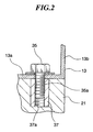
- Fig.2 is an enlarged front sectional view of the connecting portion between the plate fin type radiator 21 and the heat pipe.
- the contacting portion 13a which is a bottom of the L-shaped heat pipe 13, is contacted with the top face of the heat exchanger 21. And, both of them are tightened together by a bolt 35.
- a female screw thread 37a of the heat exchanger 21 is formed in a lock insert 37.
- the lock insert 37 is made of a relatively hard material, such as stainless steel and the like, and is a hollow cylindrical part with the female screw thread formed in the inside thereof.
- the lock insert 37 is secured in a hole of the heat exchanger 21 by the spring force of itself(interference fit) and the friction force with the male screw.
- the strength of the connection using the female screw thread 37a is improved so that the bolt 35 can be firmly tightened.
- the contact between the heat pipe contacting portion 13a and the heat exchanger 21 becomes so tight as to be able to decrease the thermal resistance between them.
- a high heat conduction grease for example, STYCAST910-50-40 made by Emerson & Cuming Co.
- a high heat conduction sheet for example, THERMATTACH TAPE made by Comerics Co.
- a high heat conduction gel for example, Si gel made by SUZUKI SOUGYOU
- Si gel made by SUZUKI SOUGYOU can be also used so that, by removing an air space in the heat exchanger surface of the contacting portion, the sealability can be improved.
- the heat produced from the element (not shown) on the board 19 is transferred to the board 19, and through the board 19 in the left and right directions to the brackets 15. Further, the heat is transferred from the brackets 15 to the heat pipe sidewalls 13b and is then transferred through the inside of the heat pipe and from the heat pipe contacting portion 13a to the heat exchanger 21.
- the heat exchanger 21 which is cooled be air or liquid, radiates the heat out to the air.
- the heat transferring medium evaporates at the sidewall 13b and condenses at the contacting portion 13a.
- the heat transferring medium is circulated through the meandering capillary in the heat pipe 13. This heat transfer associated with the evaporating and condensing of the heating medium is so efficiently carried out that the heat is able to be transferred for a long distance in the heat pipe 13 with a low thermal resistance.
- the thickness of the heat pipe 13 is about between 0.5 and 15 mm
- the diameter of the meandering capillary is about between 0.2 and 10 mm
- the pitch of the meandering capillary is about between 0.3 and 20 mm
- the thermal resistance is about between 0.01 and 2.0 °C/W.
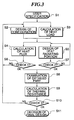
- Fig.3 is a flowchart of the basic design of the electronic component cooling apparatus.
- S1 a user specification is provided(S1).
- the user specification includes the amount of heat produced by the board, a size of the boards, the number of boards, a size of the electronic component cooling apparatus, a size of the heat radiating portion, amount of cooling air (or water), a temperature of the cooling air and a temperature of the water, and the like.
- the configuration (the first) of the electronic component cooling apparatus is determined(S2). And, a heat load is calculated(S3). Next, a heat flux is calculated(S4) and the shape of the heat radiating portion, and the like, is designed(S5).
- the check 1(S6) it is checked whether the heat flux is in the preferred range (above-mentioned) or not. In the case that the check is NG, the flow goes back to S2, and the shape of the electronic component cooling apparatus will be corrected.
- the design of the heat radiating portion, at the check 2(S7) it is checked whether the design of the heat radiating portion is in the preferred range (above-mentioned) or not. In the case that the check is NG, the flow goes back to S5, and the dimension and shape of the heat radiating portion for the electronic component will be corrected.
- Fig.4 shows a heat transfer model (the thermal resistance of each part) of the electronic component cooling apparatus according to one embodiment of the present invention.
- the symbols in Fig.4 are as follows.
- R1-2 the thermal resistance between the center and the end of the board
- R2-3 the thermal resistance between the end of the board or the wedge clamp and the bracket
- R3-4 the thermal resistance between the bracket and the sidewall of the heat pipe
- R4-5a the thermal resistance in the sidewall of the heat pipe
- R5a-5d the thermal resistance in the sidewall of the heat pipe
- R5d-6 the thermal resistance in the contacting portion of the heat pipe
- R6-7 the thermal resistance between the heat pipe connecting portion and the plate fin type radiator
- R7-8 the thermal resistance in the plate fin type radiator
- R0-8 the thermal resistance in the cooling air.
- Fig. 5 is a graph of a calculation example of the electronic component cooling apparatus according to one embodiment of the present invention.
- the abscissa shows the thermal resistance(°C/W), and the ordinate shows the temperature rise.
- the broken line shows the characteristics of the electronic component cooling apparatus according to the present embodiment, and the solid line shows the characteristics of the comparative example.
- the comparative example is an example of replacing the heat pipe of the embodiment according to the present invention with an aluminum plate.
- the total thermal resistance (between the center of the board and the cooling air) of the embodiment according to the present invention is low (about 1.1°C/W) and the temperature rise of the board is low (about 40°C ⁇ 154°C; 114°C rising).
- the total thermal resistance is high(about 2.1°C /W) and the temperature rise of the board is high (about 40°C ⁇ 295°C; 255°C rising). The reason for this is because the thermal resistance in the heat pipe is very low (about 0.1°C/W), but the thermal resistance in the aluminum plate is high (about 0.9°C/W).
- the electronic component cooling apparatus according to the above-described embodiment of the present invention, the heat transfer efficiency is so improved that the boards or the elements can be sufficiently cooled.
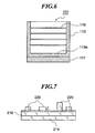
- Fig.6 is a schematic view of an electronic component cooling apparatus according to another embodiment of the present invention.
- the connecting portion 113a of the heat pipe 113 is formed over the full surface of the width direction of the heat exchanger 121.
- the symbol 119 in Fig.6 shows a printed board.
- Fig.7 is a schematic view of an electronic component cooling apparatus according to still another embodiment of the present invention.
- a plate type heat pipe 214 is attached.
- Fig.8 is a schematic view of another embodiment of the arrangement shown in Fig.7.
- a board 314 itself is comprised of a heat pipe. In this case, since there is no thermal resistance between the board and the heat pipe, the thermal resistance is further decreased.
- Fig.9 is a schematic view of still another embodiment of the arrangement shown in Fig.8.
- all of the boards 414 are made of a heat pipe.
- the heat is transferred through the sidewall 413 of the heat pipe to a plate fin type radiator (heat radiating portion)421 via connecting portion 413a.
- the present invention provides an electronic component cooling apparatus which has sufficient coolability, even when the distance between the heat radiating portion of the plate fin type radiator and the like, and the electronic component is great, and also provides improved flexibility in design.
Landscapes
- Engineering & Computer Science (AREA)
- Physics & Mathematics (AREA)
- Thermal Sciences (AREA)
- Life Sciences & Earth Sciences (AREA)
- Sustainable Development (AREA)
- Mechanical Engineering (AREA)
- General Engineering & Computer Science (AREA)
- Aviation & Aerospace Engineering (AREA)
- Microelectronics & Electronic Packaging (AREA)
- Cooling Or The Like Of Semiconductors Or Solid State Devices (AREA)
- Cooling Or The Like Of Electrical Apparatus (AREA)
- Details Of Measuring And Other Instruments (AREA)
Claims (12)
- Appareil de refroidissement (1) pour un composant électronique ou une carte (par ex. 19) sur laquelle le composant électronique est monté, l'appareil comprenant :un radiateur (21) refroidi par air ou refroidi par liquide ; etun caloduc à tube capillaire (par ex. 13) agencé pour transférer la chaleur entre: (a) le composant électronique ou la carte (19) et (b) le radiateur (21);dans lequel:(i) le caloduc à tube capillaire (13) comprend un capillaire fermé hermétiquement (13c) ;(ii) une partie du capillaire (13c) agit en tant que partie de rayonnement de chaleur et une autre partie du capillaire (13c) agit en tant que partie de réception de chaleur ;(iii) la partie de réception de chaleur et la partie de rayonnement de chaleur sont agencées de manière alternée;(iv) un fluide de travail condensable à deux phases est enfermé hermétiquement à l'intérieur du capillaire (13c) ; et(v) le capillaire (13c) a un diamètre inférieur à un diamètre maximum qui permet au fluide de travail condensable à deux phases de circuler et de se déplacer tandis qu'il est enfermé hermétiquement à l'intérieur du capillaire (13c),caractérisé en ce que
le capillaire (13c) serpente entre la partie de réception de chaleur et la partie de rayonnement de chaleur, et une pluralité de cartes (19) sont prévues, sur lesquelles des composants électroniques (par ex. 220) sont montés, les cartes (19) étant agencées en une rangée, dans lequel l'appareil comprend:un radiateur (21) refroidi par air ou refroidi par liquide du type à plaques-ailettes ; etle caloduc étant un caloduc à tube capillaire (13) serpentant du type à plaques qui transfère la chaleur entre les faces d'extrémité des cartes (19) et le radiateur (21) ;dans lequel le caloduc à tube capillaire (13) serpentant du type à plaques comprend une première partie qui est une paroi latérale (13b) de l'appareil de refroidissement de composant électronique (1), et une deuxième partie qui est pliée à une extrémité de la paroi latérale (13b) et qui est reliée le long du radiateur (21). - Appareil de refroidissement selon la revendication 1, dans lequel :le radiateur (21) comprend un ensemble d'ailettes de rayonnement, et a une forme extérieure de plaque sensiblement plate ; etle caloduc du type à plaques est relié le long du radiateur (21).
- Appareil de refroidissement selon la revendication 2, dans lequel une résistance thermique au niveau d'une partie de liaison (13a) entre le radiateur (21) et le caloduc capillaire (13) serpentant est entre environ 0,001 °C/W et environ 3,00 °C/W, et un flux thermique est entre environ 0,01 W/cm2 et environ 30 W/cm2.
- Appareil de refroidissement selon la revendication 2, dans lequel une résistance thermique au niveau d'une surface de contact entre une surface d'extrémité de la carte (19) sur laquelle le composant électronique est monté et le caloduc à tube capillaire (13) serpentant est entre environ 0,001 °C/W et environ 3,00 °C/W, et un flux thermique est entre environ 0,01 W/cm2 et environ 30 W/cm2.
- Appareil de refroidissement selon la revendication 2, dans lequel:le caloduc à tube capillaire (13) serpentant est fixé au radiateur (21) par une vis (35) ; etun trou de vis fileté (37a) est formé dans un insert de verrouillage (37) qui est monté dans le radiateur (21).
- Appareil de refroidissement selon la revendication 1, comprenant en outre des supports (15) montés entre les faces d'extrémité des cartes (19) et le caloduc à tube capillaire (13) serpentant du type à plaques pour fixer les plaques (19) au caloduc à tube capillaire (13) serpentant du type à plaques.
- Appareil de refroidissement selon la revendication 6, dans lequel les supports (15) sont fixés au caloduc à tube capillaire (13) serpentant du type à plaques par au moins l'une d'une vis (31) et d'une soudure (33).
- Appareil de refroidissement selon la revendication 6, dans lequel les supports (15) sont fixés au caloduc à tube capillaire (13) serpentant du type à plaques à la fois par une vis (31) et une soudure (33).
- Appareil de refroidissement selon la revendication 1, dans lequel une résistance thermique au niveau d'une partie de liaison (13a) entre le radiateur (21) et le caloduc à tube capillaire (13) serpentant du type à plaques est entre environ 0,001 °C/W et environ 3,00 °C/W, et un flux thermique est entre environ 0,01 W/cm2 et environ 30 W/cm2.
- Appareil de refroidissement selon la revendication 1, dans lequel une résistance thermique au niveau d'une surface de contact entre les faces d'extrémité des cartes (19) et le caloduc à tube capillaire (13) serpentant du type à plaques est entre environ 0,001 °C/W et environ 3,00 °C/W, et un flux thermique est entre environ 0,01 W/cm2 et environ 30 W/cm2.
- Appareil de refroidissement selon la revendication 1, dans lequel :le caloduc à tube capillaire (13) serpentant du type à plaques est fixé au radiateur (21) par une vis ; etun trou de vis fileté (37a) est formé dans un insert de verrouillage (37) qui est monté dans le radiateur (21).
- Appareil de refroidissement selon la revendication 1, dans lequel:le caloduc à tube capillaire (214) serpentant est fixé à la carte (219) le long d'une surface de face de la carte (219).
Applications Claiming Priority (4)
| Application Number | Priority Date | Filing Date | Title |
|---|---|---|---|
| JP13960699 | 1999-05-20 | ||
| JP13960699 | 1999-05-20 | ||
| JP14686799A JP4223628B2 (ja) | 1999-05-20 | 1999-05-26 | 電子機器冷却装置 |
| JP14686799 | 1999-05-26 |
Publications (3)
| Publication Number | Publication Date |
|---|---|
| EP1054583A2 EP1054583A2 (fr) | 2000-11-22 |
| EP1054583A3 EP1054583A3 (fr) | 2001-06-20 |
| EP1054583B1 true EP1054583B1 (fr) | 2007-03-07 |
Family
ID=26472359
Family Applications (1)
| Application Number | Title | Priority Date | Filing Date |
|---|---|---|---|
| EP00110248A Expired - Lifetime EP1054583B1 (fr) | 1999-05-20 | 2000-05-19 | Appareil pour refroidir des composants électroniques |
Country Status (5)
| Country | Link |
|---|---|
| US (1) | US6360813B1 (fr) |
| EP (1) | EP1054583B1 (fr) |
| JP (1) | JP4223628B2 (fr) |
| AT (1) | ATE356540T1 (fr) |
| DE (1) | DE60033727D1 (fr) |
Cited By (1)
| Publication number | Priority date | Publication date | Assignee | Title |
|---|---|---|---|---|
| US7907409B2 (en) | 2008-03-25 | 2011-03-15 | Raytheon Company | Systems and methods for cooling a computing component in a computing rack |
Families Citing this family (36)
| Publication number | Priority date | Publication date | Assignee | Title |
|---|---|---|---|---|
| US6762907B2 (en) * | 2001-06-07 | 2004-07-13 | Hewlett-Packard Development Company, L.P. | Disc drive having integral base cooling |
| WO2002102124A2 (fr) * | 2001-06-12 | 2002-12-19 | Liebert Corporation | Systeme de transfert thermique a bus simple ou double |
| US6536510B2 (en) * | 2001-07-10 | 2003-03-25 | Thermal Corp. | Thermal bus for cabinets housing high power electronics equipment |
| USD475354S1 (en) | 2001-12-21 | 2003-06-03 | Tung-Yuan Wang | Heat pipe of radiator of computer |
| US6819561B2 (en) * | 2002-02-22 | 2004-11-16 | Satcon Technology Corporation | Finned-tube heat exchangers and cold plates, self-cooling electronic component systems using same, and methods for cooling electronic components using same |
| US20050213306A1 (en) * | 2004-03-25 | 2005-09-29 | Lockheed Martin Corporation | Environmental control method and apparatus for electronic device enclosures |
| WO2006080793A2 (fr) * | 2005-01-27 | 2006-08-03 | Lg Electronics, Inc. | Unite interieure de climatiseur |
| WO2006137763A1 (fr) * | 2005-06-23 | 2006-12-28 | Telefonaktiebolaget Lm Ericsson (Publ) | Ensemble de refroidissement |
| DE102005036299B4 (de) * | 2005-08-02 | 2008-01-24 | Siemens Ag | Kühlanordnung |
| US8240359B2 (en) * | 2006-04-17 | 2012-08-14 | Gerald Garrett | Liquid storage and cooling computer case |
| US8651172B2 (en) | 2007-03-22 | 2014-02-18 | Raytheon Company | System and method for separating components of a fluid coolant for cooling a structure |
| US20090165996A1 (en) * | 2007-12-26 | 2009-07-02 | Lynch Thomas W | Reticulated heat dissipation with coolant |
| US8582298B2 (en) * | 2009-06-22 | 2013-11-12 | Xyber Technologies | Passive cooling enclosure system and method for electronics devices |
| US9036351B2 (en) * | 2009-06-22 | 2015-05-19 | Xyber Technologies, Llc | Passive cooling system and method for electronics devices |
| US8816220B2 (en) * | 2011-01-28 | 2014-08-26 | Raytheon Company | Enclosure cooling apparatus |
| DE102011119174A1 (de) * | 2011-11-23 | 2013-05-23 | Inheco Industrial Heating And Cooling Gmbh | Vapor Chamber |
| FR2984472B1 (fr) * | 2011-12-20 | 2015-10-02 | Astrium Sas | Dispositif de regulation thermique passif |
| US10209003B2 (en) | 2012-02-21 | 2019-02-19 | Thermal Corp. | Electronics cabinet and rack cooling system and method |
| EP2848101B1 (fr) | 2012-05-07 | 2019-04-10 | Phononic Devices, Inc. | Composant d'échangeur de chaleur thermoélectrique comprenant un couvercle d'étalement de la chaleur protecteur et une résistance d'interface thermique optimale |
| US20130291555A1 (en) | 2012-05-07 | 2013-11-07 | Phononic Devices, Inc. | Thermoelectric refrigeration system control scheme for high efficiency performance |
| EP3131376B1 (fr) * | 2014-06-04 | 2021-08-04 | Huawei Technologies Co., Ltd. | Dispositif électronique |
| US9593871B2 (en) | 2014-07-21 | 2017-03-14 | Phononic Devices, Inc. | Systems and methods for operating a thermoelectric module to increase efficiency |
| US10458683B2 (en) | 2014-07-21 | 2019-10-29 | Phononic, Inc. | Systems and methods for mitigating heat rejection limitations of a thermoelectric module |
| US10209009B2 (en) | 2016-06-21 | 2019-02-19 | General Electric Company | Heat exchanger including passageways |
| CN107734829A (zh) * | 2017-09-25 | 2018-02-23 | 郑州云海信息技术有限公司 | 一种高效的pcb内层散热系统及实现方法 |
| US11427330B2 (en) | 2019-11-15 | 2022-08-30 | General Electric Company | System and method for cooling a leading edge of a high speed vehicle |
| US11260953B2 (en) | 2019-11-15 | 2022-03-01 | General Electric Company | System and method for cooling a leading edge of a high speed vehicle |
| US11267551B2 (en) | 2019-11-15 | 2022-03-08 | General Electric Company | System and method for cooling a leading edge of a high speed vehicle |
| US11260976B2 (en) | 2019-11-15 | 2022-03-01 | General Electric Company | System for reducing thermal stresses in a leading edge of a high speed vehicle |
| US11352120B2 (en) | 2019-11-15 | 2022-06-07 | General Electric Company | System and method for cooling a leading edge of a high speed vehicle |
| DE102020107173A1 (de) | 2020-03-16 | 2021-09-16 | Bayerische Motoren Werke Aktiengesellschaft | Kühlungsanordnung für zumindest eine stromführende Komponente eines Kraftfahrzeugs |
| US11425842B2 (en) | 2020-09-14 | 2022-08-23 | Hewlett Packard Enterprise Development Lp | Thermal design of an access point |
| DE102020212698A1 (de) | 2020-10-08 | 2022-04-14 | Robert Bosch Gesellschaft mit beschränkter Haftung | Anordnung, Abgasnachbehandlungssystem |
| US11745847B2 (en) | 2020-12-08 | 2023-09-05 | General Electric Company | System and method for cooling a leading edge of a high speed vehicle |
| US11407488B2 (en) | 2020-12-14 | 2022-08-09 | General Electric Company | System and method for cooling a leading edge of a high speed vehicle |
| US11577817B2 (en) | 2021-02-11 | 2023-02-14 | General Electric Company | System and method for cooling a leading edge of a high speed vehicle |
Family Cites Families (19)
| Publication number | Priority date | Publication date | Assignee | Title |
|---|---|---|---|---|
| DE3044314C2 (de) * | 1980-11-25 | 1986-08-14 | kabelmetal electro GmbH, 3000 Hannover | Gehäuse zur Aufnahme von mit Wärme erzeugenden elektronischen Bauteilen bestückten gedruckten Schaltungen |
| US4616699A (en) * | 1984-01-05 | 1986-10-14 | Mcdonnell Douglas Corporation | Wick-fin heat pipe |
| DE3679978D1 (de) * | 1985-12-13 | 1991-08-01 | Hasler Ag Ascom | Verfahren und vorrichtung zum abfuehren der verlustwaerme wenigstens einer baugruppe elektrischer elemente. |
| JPH0697147B2 (ja) | 1990-11-22 | 1994-11-30 | アクトロニクス株式会社 | ループ型細管ヒートパイプ |
| US5219020A (en) | 1990-11-22 | 1993-06-15 | Actronics Kabushiki Kaisha | Structure of micro-heat pipe |
| FR2682746B1 (fr) | 1991-10-17 | 1994-01-28 | Etudes Electroniques Mecaniques | Echangeur de chaleur destine aux dissipateurs thermiques a effet caloduc et comportant une structure a plusieurs etages d'echanges thermiques. |
| JP2873765B2 (ja) | 1992-04-13 | 1999-03-24 | アクトロニクス 株式会社 | ▲l▼字形状ピン群を有する剣山型ヒートシンク |
| US5283715A (en) * | 1992-09-29 | 1994-02-01 | International Business Machines, Inc. | Integrated heat pipe and circuit board structure |
| US5343940A (en) * | 1992-10-29 | 1994-09-06 | Amigo Jean | Flexible heat transfer device |
| JP2544701B2 (ja) | 1993-08-24 | 1996-10-16 | アクトロニクス株式会社 | プレ―ト形ヒ―トパイプ |
| US5697428A (en) | 1993-08-24 | 1997-12-16 | Actronics Kabushiki Kaisha | Tunnel-plate type heat pipe |
| JPH07211826A (ja) * | 1994-01-13 | 1995-08-11 | Toyo Electric Mfg Co Ltd | 電気車用半導体冷却装置 |
| DE19515095A1 (de) | 1995-04-25 | 1996-10-31 | Dornier Gmbh | Kapillarverdampfer |
| US5507092A (en) | 1995-06-06 | 1996-04-16 | Hisateru Akachi | L-type heat sink |
| DE69615946T2 (de) | 1995-07-14 | 2002-04-04 | Actronics K.K., Isehara | Verfahren zur Herstellung von Tunnelplatten-Wärmerohren |
| JP3932518B2 (ja) | 1995-08-09 | 2007-06-20 | アクトロニクス株式会社 | 細径トンネルプレートヒートパイプの製造方法 |
| US6104611A (en) * | 1995-10-05 | 2000-08-15 | Nortel Networks Corporation | Packaging system for thermally controlling the temperature of electronic equipment |
| CA2199239A1 (fr) | 1997-03-05 | 1998-09-05 | Trevor Zapach | Appareil electronique |
| US6115251A (en) * | 1999-04-15 | 2000-09-05 | Hewlett Packard Company | Cooling apparatus for computer subsystem |
-
1999
- 1999-05-26 JP JP14686799A patent/JP4223628B2/ja not_active Expired - Fee Related
-
2000
- 2000-05-19 AT AT00110248T patent/ATE356540T1/de not_active IP Right Cessation
- 2000-05-19 EP EP00110248A patent/EP1054583B1/fr not_active Expired - Lifetime
- 2000-05-19 US US09/574,484 patent/US6360813B1/en not_active Expired - Lifetime
- 2000-05-19 DE DE60033727T patent/DE60033727D1/de not_active Expired - Lifetime
Cited By (1)
| Publication number | Priority date | Publication date | Assignee | Title |
|---|---|---|---|---|
| US7907409B2 (en) | 2008-03-25 | 2011-03-15 | Raytheon Company | Systems and methods for cooling a computing component in a computing rack |
Also Published As
| Publication number | Publication date |
|---|---|
| JP2001035976A (ja) | 2001-02-09 |
| DE60033727D1 (de) | 2007-04-19 |
| US6360813B1 (en) | 2002-03-26 |
| EP1054583A2 (fr) | 2000-11-22 |
| ATE356540T1 (de) | 2007-03-15 |
| EP1054583A3 (fr) | 2001-06-20 |
| JP4223628B2 (ja) | 2009-02-12 |
Similar Documents
| Publication | Publication Date | Title |
|---|---|---|
| US6360813B1 (en) | Electronic components cooling apparatus | |
| EP2677261B1 (fr) | Système de refroidissement biphasé pour composants électroniques | |
| US8958208B2 (en) | Semiconductor device | |
| US20070144707A1 (en) | Cooling assembly with successively contracting and expanding coolant flow | |
| JPH08264695A (ja) | 電子部品用冷却装置 | |
| US11876036B2 (en) | Fluid cooling system including embedded channels and cold plates | |
| JPH10215094A (ja) | Pcカードアレイからの熱除去装置 | |
| JP2004111968A (ja) | 部品と直接接触したヒートパイプ付きヒートシンク | |
| US20250344343A1 (en) | Liquid-cooling devices, and systems, to cool multi-chip modules | |
| US20220046827A1 (en) | Server | |
| WO2025039711A1 (fr) | Dispositif de dissipation de chaleur et serveur | |
| JP4150647B2 (ja) | 電子部品の冷却装置 | |
| CN115003121B (zh) | 一种可实现电子元器件集中散热及密封的结构及制备方法 | |
| CN218473718U (zh) | 散热装置 | |
| CN218550265U (zh) | 电路板散热装置和电子设备 | |
| JP4229738B2 (ja) | ヒートパイプ式放熱ユニット | |
| JP3810119B2 (ja) | 沸騰冷却装置 | |
| EP4668057A1 (fr) | Système de refroidissement par liquide | |
| TWI922323B (zh) | 主機板冷卻系統及主機殼 | |
| CN217770750U (zh) | 一种组合式散热模组 | |
| CN215062455U (zh) | 一种空调器 | |
| JPH065749A (ja) | 放熱装置 | |
| JPH06216554A (ja) | 電子部品のヒートパイプ式冷却装置 | |
| CN117613021A (zh) | 一种水冷恒温散热器 | |
| JPH08250629A (ja) | 熱交換器 |
Legal Events
| Date | Code | Title | Description |
|---|---|---|---|
| PUAI | Public reference made under article 153(3) epc to a published international application that has entered the european phase |
Free format text: ORIGINAL CODE: 0009012 |
|
| AK | Designated contracting states |
Kind code of ref document: A2 Designated state(s): AT BE CH CY DE DK ES FI FR GB GR IE IT LI LU MC NL PT SE |
|
| AX | Request for extension of the european patent |
Free format text: AL;LT;LV;MK;RO;SI |
|
| PUAL | Search report despatched |
Free format text: ORIGINAL CODE: 0009013 |
|
| AK | Designated contracting states |
Kind code of ref document: A3 Designated state(s): AT BE CH CY DE DK ES FI FR GB GR IE IT LI LU MC NL PT SE |
|
| AX | Request for extension of the european patent |
Free format text: AL;LT;LV;MK;RO;SI |
|
| 17P | Request for examination filed |
Effective date: 20011217 |
|
| AKX | Designation fees paid |
Free format text: AT BE CH CY DE DK ES FI FR GB GR IE IT LI LU MC NL PT SE |
|
| 17Q | First examination report despatched |
Effective date: 20041025 |
|
| GRAP | Despatch of communication of intention to grant a patent |
Free format text: ORIGINAL CODE: EPIDOSNIGR1 |
|
| GRAS | Grant fee paid |
Free format text: ORIGINAL CODE: EPIDOSNIGR3 |
|
| GRAA | (expected) grant |
Free format text: ORIGINAL CODE: 0009210 |
|
| AK | Designated contracting states |
Kind code of ref document: B1 Designated state(s): AT BE CH CY DE DK ES FI FR GB GR IE IT LI LU MC NL PT SE |
|
| PG25 | Lapsed in a contracting state [announced via postgrant information from national office to epo] |
Ref country code: NL Free format text: LAPSE BECAUSE OF FAILURE TO SUBMIT A TRANSLATION OF THE DESCRIPTION OR TO PAY THE FEE WITHIN THE PRESCRIBED TIME-LIMIT Effective date: 20070307 Ref country code: LI Free format text: LAPSE BECAUSE OF FAILURE TO SUBMIT A TRANSLATION OF THE DESCRIPTION OR TO PAY THE FEE WITHIN THE PRESCRIBED TIME-LIMIT Effective date: 20070307 Ref country code: FI Free format text: LAPSE BECAUSE OF FAILURE TO SUBMIT A TRANSLATION OF THE DESCRIPTION OR TO PAY THE FEE WITHIN THE PRESCRIBED TIME-LIMIT Effective date: 20070307 Ref country code: AT Free format text: LAPSE BECAUSE OF FAILURE TO SUBMIT A TRANSLATION OF THE DESCRIPTION OR TO PAY THE FEE WITHIN THE PRESCRIBED TIME-LIMIT Effective date: 20070307 Ref country code: CH Free format text: LAPSE BECAUSE OF FAILURE TO SUBMIT A TRANSLATION OF THE DESCRIPTION OR TO PAY THE FEE WITHIN THE PRESCRIBED TIME-LIMIT Effective date: 20070307 Ref country code: BE Free format text: LAPSE BECAUSE OF FAILURE TO SUBMIT A TRANSLATION OF THE DESCRIPTION OR TO PAY THE FEE WITHIN THE PRESCRIBED TIME-LIMIT Effective date: 20070307 |
|
| REG | Reference to a national code |
Ref country code: GB Ref legal event code: FG4D |
|
| REG | Reference to a national code |
Ref country code: CH Ref legal event code: EP |
|
| REF | Corresponds to: |
Ref document number: 60033727 Country of ref document: DE Date of ref document: 20070419 Kind code of ref document: P |
|
| REG | Reference to a national code |
Ref country code: IE Ref legal event code: FG4D |
|
| PG25 | Lapsed in a contracting state [announced via postgrant information from national office to epo] |
Ref country code: SE Free format text: LAPSE BECAUSE OF FAILURE TO SUBMIT A TRANSLATION OF THE DESCRIPTION OR TO PAY THE FEE WITHIN THE PRESCRIBED TIME-LIMIT Effective date: 20070607 |
|
| PG25 | Lapsed in a contracting state [announced via postgrant information from national office to epo] |
Ref country code: ES Free format text: LAPSE BECAUSE OF FAILURE TO SUBMIT A TRANSLATION OF THE DESCRIPTION OR TO PAY THE FEE WITHIN THE PRESCRIBED TIME-LIMIT Effective date: 20070618 |
|
| PG25 | Lapsed in a contracting state [announced via postgrant information from national office to epo] |
Ref country code: PT Free format text: LAPSE BECAUSE OF FAILURE TO SUBMIT A TRANSLATION OF THE DESCRIPTION OR TO PAY THE FEE WITHIN THE PRESCRIBED TIME-LIMIT Effective date: 20070807 |
|
| ET | Fr: translation filed | ||
| NLV1 | Nl: lapsed or annulled due to failure to fulfill the requirements of art. 29p and 29m of the patents act | ||
| REG | Reference to a national code |
Ref country code: CH Ref legal event code: PL |
|
| PLBE | No opposition filed within time limit |
Free format text: ORIGINAL CODE: 0009261 |
|
| STAA | Information on the status of an ep patent application or granted ep patent |
Free format text: STATUS: NO OPPOSITION FILED WITHIN TIME LIMIT |
|
| PG25 | Lapsed in a contracting state [announced via postgrant information from national office to epo] |
Ref country code: MC Free format text: LAPSE BECAUSE OF NON-PAYMENT OF DUE FEES Effective date: 20070531 Ref country code: DE Free format text: LAPSE BECAUSE OF FAILURE TO SUBMIT A TRANSLATION OF THE DESCRIPTION OR TO PAY THE FEE WITHIN THE PRESCRIBED TIME-LIMIT Effective date: 20070609 Ref country code: DK Free format text: LAPSE BECAUSE OF FAILURE TO SUBMIT A TRANSLATION OF THE DESCRIPTION OR TO PAY THE FEE WITHIN THE PRESCRIBED TIME-LIMIT Effective date: 20070307 |
|
| 26N | No opposition filed |
Effective date: 20071210 |
|
| GBPC | Gb: european patent ceased through non-payment of renewal fee |
Effective date: 20070607 |
|
| PG25 | Lapsed in a contracting state [announced via postgrant information from national office to epo] |
Ref country code: GR Free format text: LAPSE BECAUSE OF FAILURE TO SUBMIT A TRANSLATION OF THE DESCRIPTION OR TO PAY THE FEE WITHIN THE PRESCRIBED TIME-LIMIT Effective date: 20070608 Ref country code: IT Free format text: LAPSE BECAUSE OF FAILURE TO SUBMIT A TRANSLATION OF THE DESCRIPTION OR TO PAY THE FEE WITHIN THE PRESCRIBED TIME-LIMIT Effective date: 20070307 |
|
| PG25 | Lapsed in a contracting state [announced via postgrant information from national office to epo] |
Ref country code: GB Free format text: LAPSE BECAUSE OF NON-PAYMENT OF DUE FEES Effective date: 20070607 Ref country code: IE Free format text: LAPSE BECAUSE OF NON-PAYMENT OF DUE FEES Effective date: 20070521 |
|
| PG25 | Lapsed in a contracting state [announced via postgrant information from national office to epo] |
Ref country code: CY Free format text: LAPSE BECAUSE OF FAILURE TO SUBMIT A TRANSLATION OF THE DESCRIPTION OR TO PAY THE FEE WITHIN THE PRESCRIBED TIME-LIMIT Effective date: 20070307 |
|
| PG25 | Lapsed in a contracting state [announced via postgrant information from national office to epo] |
Ref country code: LU Free format text: LAPSE BECAUSE OF NON-PAYMENT OF DUE FEES Effective date: 20070519 |
|
| PGFP | Annual fee paid to national office [announced via postgrant information from national office to epo] |
Ref country code: FR Payment date: 20110523 Year of fee payment: 12 |
|
| REG | Reference to a national code |
Ref country code: FR Ref legal event code: ST Effective date: 20130131 |
|
| PG25 | Lapsed in a contracting state [announced via postgrant information from national office to epo] |
Ref country code: FR Free format text: LAPSE BECAUSE OF NON-PAYMENT OF DUE FEES Effective date: 20120531 |