EP1054737B1 - Procede et dispositif pour separer des particules a conductions electriques differentes - Google Patents
Procede et dispositif pour separer des particules a conductions electriques differentes Download PDFInfo
- Publication number
- EP1054737B1 EP1054737B1 EP99906222A EP99906222A EP1054737B1 EP 1054737 B1 EP1054737 B1 EP 1054737B1 EP 99906222 A EP99906222 A EP 99906222A EP 99906222 A EP99906222 A EP 99906222A EP 1054737 B1 EP1054737 B1 EP 1054737B1
- Authority
- EP
- European Patent Office
- Prior art keywords
- particles
- eddy
- separated
- magnet system
- cooled
- Prior art date
- Legal status (The legal status is an assumption and is not a legal conclusion. Google has not performed a legal analysis and makes no representation as to the accuracy of the status listed.)
- Expired - Lifetime
Links
- 239000002245 particle Substances 0.000 title claims abstract description 59
- 238000000034 method Methods 0.000 title claims abstract description 16
- 238000001816 cooling Methods 0.000 claims abstract description 25
- 238000000926 separation method Methods 0.000 claims abstract description 25
- 239000000463 material Substances 0.000 claims abstract description 13
- 239000002699 waste material Substances 0.000 claims abstract description 7
- IJGRMHOSHXDMSA-UHFFFAOYSA-N Atomic nitrogen Chemical compound N#N IJGRMHOSHXDMSA-UHFFFAOYSA-N 0.000 claims description 18
- 229910052757 nitrogen Inorganic materials 0.000 claims description 9
- CWYNVVGOOAEACU-UHFFFAOYSA-N Fe2+ Chemical compound [Fe+2] CWYNVVGOOAEACU-UHFFFAOYSA-N 0.000 claims description 6
- 239000007788 liquid Substances 0.000 claims description 4
- 239000002923 metal particle Substances 0.000 claims description 2
- XEEYBQQBJWHFJM-UHFFFAOYSA-N Iron Chemical compound [Fe] XEEYBQQBJWHFJM-UHFFFAOYSA-N 0.000 abstract description 6
- 230000001965 increasing effect Effects 0.000 abstract description 6
- 229910052742 iron Inorganic materials 0.000 abstract description 3
- 239000013528 metallic particle Substances 0.000 abstract 1
- 238000011144 upstream manufacturing Methods 0.000 abstract 1
- 229910052751 metal Inorganic materials 0.000 description 15
- 239000002184 metal Substances 0.000 description 15
- -1 ferrous metals Chemical class 0.000 description 10
- 230000005291 magnetic effect Effects 0.000 description 8
- RYGMFSIKBFXOCR-UHFFFAOYSA-N Copper Chemical compound [Cu] RYGMFSIKBFXOCR-UHFFFAOYSA-N 0.000 description 5
- 229910052782 aluminium Inorganic materials 0.000 description 5
- XAGFODPZIPBFFR-UHFFFAOYSA-N aluminium Chemical compound [Al] XAGFODPZIPBFFR-UHFFFAOYSA-N 0.000 description 5
- FYYHWMGAXLPEAU-UHFFFAOYSA-N Magnesium Chemical compound [Mg] FYYHWMGAXLPEAU-UHFFFAOYSA-N 0.000 description 4
- HCHKCACWOHOZIP-UHFFFAOYSA-N Zinc Chemical compound [Zn] HCHKCACWOHOZIP-UHFFFAOYSA-N 0.000 description 4
- 229910052802 copper Inorganic materials 0.000 description 4
- 239000010949 copper Substances 0.000 description 4
- 239000011777 magnesium Substances 0.000 description 4
- 229910052749 magnesium Inorganic materials 0.000 description 4
- 230000000694 effects Effects 0.000 description 3
- 230000001939 inductive effect Effects 0.000 description 3
- 239000011701 zinc Substances 0.000 description 3
- 229910052725 zinc Inorganic materials 0.000 description 3
- 230000003247 decreasing effect Effects 0.000 description 2
- 238000004064 recycling Methods 0.000 description 2
- 239000000126 substance Substances 0.000 description 2
- 238000010521 absorption reaction Methods 0.000 description 1
- 238000005054 agglomeration Methods 0.000 description 1
- 230000002776 aggregation Effects 0.000 description 1
- 239000004411 aluminium Substances 0.000 description 1
- 238000009835 boiling Methods 0.000 description 1
- 239000004020 conductor Substances 0.000 description 1
- 238000010276 construction Methods 0.000 description 1
- 239000002826 coolant Substances 0.000 description 1
- 230000001419 dependent effect Effects 0.000 description 1
- 238000010586 diagram Methods 0.000 description 1
- 238000005516 engineering process Methods 0.000 description 1
- 230000005294 ferromagnetic effect Effects 0.000 description 1
- 239000003302 ferromagnetic material Substances 0.000 description 1
- 239000006148 magnetic separator Substances 0.000 description 1
- 239000000203 mixture Substances 0.000 description 1
- 239000012811 non-conductive material Substances 0.000 description 1
- 230000000704 physical effect Effects 0.000 description 1
- 239000002994 raw material Substances 0.000 description 1
- 230000008685 targeting Effects 0.000 description 1
Images

Classifications
-
- B—PERFORMING OPERATIONS; TRANSPORTING
- B03—SEPARATION OF SOLID MATERIALS USING LIQUIDS OR USING PNEUMATIC TABLES OR JIGS; MAGNETIC OR ELECTROSTATIC SEPARATION OF SOLID MATERIALS FROM SOLID MATERIALS OR FLUIDS; SEPARATION BY HIGH-VOLTAGE ELECTRIC FIELDS
- B03C—MAGNETIC OR ELECTROSTATIC SEPARATION OF SOLID MATERIALS FROM SOLID MATERIALS OR FLUIDS; SEPARATION BY HIGH-VOLTAGE ELECTRIC FIELDS
- B03C1/00—Magnetic separation
- B03C1/02—Magnetic separation acting directly on the substance being separated
- B03C1/23—Magnetic separation acting directly on the substance being separated with material carried by oscillating fields; with material carried by travelling fields, e.g. generated by stationary magnetic coils; Eddy-current separators, e.g. sliding ramp
- B03C1/24—Magnetic separation acting directly on the substance being separated with material carried by oscillating fields; with material carried by travelling fields, e.g. generated by stationary magnetic coils; Eddy-current separators, e.g. sliding ramp with material carried by travelling fields
- B03C1/247—Magnetic separation acting directly on the substance being separated with material carried by oscillating fields; with material carried by travelling fields, e.g. generated by stationary magnetic coils; Eddy-current separators, e.g. sliding ramp with material carried by travelling fields obtained by a rotating magnetic drum
-
- B—PERFORMING OPERATIONS; TRANSPORTING
- B03—SEPARATION OF SOLID MATERIALS USING LIQUIDS OR USING PNEUMATIC TABLES OR JIGS; MAGNETIC OR ELECTROSTATIC SEPARATION OF SOLID MATERIALS FROM SOLID MATERIALS OR FLUIDS; SEPARATION BY HIGH-VOLTAGE ELECTRIC FIELDS
- B03C—MAGNETIC OR ELECTROSTATIC SEPARATION OF SOLID MATERIALS FROM SOLID MATERIALS OR FLUIDS; SEPARATION BY HIGH-VOLTAGE ELECTRIC FIELDS
- B03C1/00—Magnetic separation
- B03C1/02—Magnetic separation acting directly on the substance being separated
- B03C1/23—Magnetic separation acting directly on the substance being separated with material carried by oscillating fields; with material carried by travelling fields, e.g. generated by stationary magnetic coils; Eddy-current separators, e.g. sliding ramp
-
- B—PERFORMING OPERATIONS; TRANSPORTING
- B03—SEPARATION OF SOLID MATERIALS USING LIQUIDS OR USING PNEUMATIC TABLES OR JIGS; MAGNETIC OR ELECTROSTATIC SEPARATION OF SOLID MATERIALS FROM SOLID MATERIALS OR FLUIDS; SEPARATION BY HIGH-VOLTAGE ELECTRIC FIELDS
- B03C—MAGNETIC OR ELECTROSTATIC SEPARATION OF SOLID MATERIALS FROM SOLID MATERIALS OR FLUIDS; SEPARATION BY HIGH-VOLTAGE ELECTRIC FIELDS
- B03C2201/00—Details of magnetic or electrostatic separation
- B03C2201/20—Magnetic separation of bulk or dry particles in mixtures
Definitions
- the invention relates to a method for separating different electrical conductive non-ferrous particles, in particular from waste materials, as well as a Device for performing the method.
- separating is of ferromagnetic substances, in particular iron, without any problems possible using simple magnetic methods.
- the further separation of Non-ferrous metals among themselves and from plastic can be removed of ferromagnetic materials due to the different electrical Conductivity by means of eddy current separation.
- the eddy current separator In the eddy current separator is in an inducing magnetic field in the guided by the magnetic field particles to be separated induce a current depending on their conductivity and thus generates a force that forces the particles out of the magnetic field.
- EP 0 305 881 A1 describes one method and one Device for sorting non-ferrous metal particles by means of a Wirbeistromabscheidung.
- a conveyor belt runs around a rotating one Magnet system and the different particles are in different Throwing parabolas are thrown out and can be sorted to a certain extent.
- EP 0 339 195 B1 describes a magnetic separator as an improved version with a via a belt drum made of non-electrically conductive material guided conveyor belt for the transport of a fraction to be sorted from more or less good electrically conductive particles with one in the belt drum higher rotational speed than that of the belt drum rotatably driven Magnet system and one in the material discharge zone of the belt drum arranged collection container for the separated electrically conductive Particles. It specifies in particular how damaged the belt drum by particles passing between the conveyor belt and the belt drum, especially iron particles can be avoided. This is done by a certain geometry in the construction.
- a disadvantage of the known eddy current separators is that separation of different non-ferrous metals with each other only with difficulty and is possible with errors. This is mainly because of the ability to separate determining physical properties only slight differences exhibit.
- the task is therefore to improve the separation of non-ferrous metals from one another to achieve in the eddy current separation.
- a device for The implementation of this method is characterized in that a Cooling chamber is provided through which the particles are guided, and that a Eddy current separator (magnet system) is provided, which is still cooled Particles are fed in a transport stream
- the ⁇ / ⁇ ratio in the temperature range differs from 100 - 300 K for aluminum, magnesium, copper and zinc, as in the one in FIG. 1 shown graphic indicated.
- the values are taken from: CRC Handbook of Chemistry and Physics, publisher: David R. Lide, born 1992 - 93, 73rd edition, publisher CRC Press, Boca Raton etc.
- the graphic shows that with decreasing temperatures both ⁇ / ⁇ for each element increases in absolute terms and ⁇ ( ⁇ / ⁇ ) for every two elements. With that is a higher yield and with a sharper separation, especially under 150 K, to be expected when separating waste.
- Cooling is therefore preferred to 100 - 150 K of the particles. It is also sufficient if at least the surfaces of the particles are cooled to the desired temperature are, since the eddy currents generated by the inducing magnetic fields in flow essentially on the surface of the particles.
- liquid nitrogen is used to cool the particles, one will achieved simple and effective cooling of the particles. Since the boiling point of Nitrogen is approximately 80 K, the preferred temperature range can at least can be achieved on the surfaces of the particles. Another influence of the Operation through the nitrogen is excluded.
- the different materials also have different thermal conductivity coefficients; they react differently quickly and differently intensely on the cooling. Because this cooling process is finite Time takes place and the separation is made in terms of time closely to the cooling the temperature of the particles to be sorted is different, despite being identical acting cooling system.
- the cooling chamber is as closed channel with a feed opening and a discharge opening for the particles to be separated. That brought in the closed channel Coolants, such as liquid nitrogen, can be metered sparingly become.
- the supply of the particles to be separated through the channel is ensured that the channel is designed as a slide or vibrating conveyor.
- the channel has a substantially rectangular cross section, a Avoid agglomeration of the particles to be separated.
- the Channel the width of the downstream conveyor belt for eddy current separation.
- To generate the guided along the rotatable magnet system Transport stream has in particular a conveyor belt made of electrically non-conductive Proven material.
- the axis of rotation of the rotatable magnet system should be parallel to the transport stream of the particles to be separated.
- the rotatable magnet system is preferred between the upper run and lower run arranged of the conveyor belt.
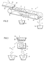
- a structure of a device according to the invention is schematically represented spatially in FIG .
- the particle stream to be separated is fed from the left and passed through a cooling chamber 2.
- the cooling chamber 2 essentially has a rectangular cross section, as can be seen in the front view in FIG. 3 .
- the cooling chamber 2 is elongated and has a feed opening (not shown) and an outlet opening 21, which is arranged directly above a conveyor belt 11.
- the conveyor belt 11 is guided over deflection rollers 12, 13. Between the upper run and the lower run of the conveyor belt 11 is a rotatable magnet system 14 arranged. The axis of rotation of the rotatable magnet system 14 is parallel aligned with the transport direction of the conveyor belt 11.
- This part forms a conventional eddy current separator 1, which is a separation differently conductive particles X, Y allowed.
- the electrically conductive Particles X experience on the conveyor belt 11 above the rotating magnet system 14 a deflection and get into a next to the conveyor belt 11 Collection container 15.
- the non-electrically conductive particles Y for example made of plastic, get over the deflection roller 13 of the conveyor belt 11 in one Collection container 16.
- the spatial arrangement of the collecting container 15, 16 is supplementary from one 3 shows a front view of the device according to the invention.
- the cooling chamber 2 consists of a closed channel, which consists of a U-shaped Lower part 22 and a cover 23 is formed.
- cooling particles X, Y fed therein are supplied with liquid nitrogen.
- the nitrogen flows through the channel 22, 23 and thus cools the surfaces in particular the particle.
- the nitrogen is wrapped around a cell, the one Contains part of the conveyor belt and the magnetic field.
- the air in the cell is brought to the desired operating temperature, preferably below 150 K, cooled and kept stable by an appropriate flow of nitrogen.
- the cooling of the material to be separated comes from heat conduction and convection conditions. Because the eddy current density is greatest on the material surface it is not necessary to bring about a complete temperature equalization. A very rough estimate shows that aluminum and copper with a thickness of 1 mm the cooling takes place in the time ⁇ 1 s, so that with the known conveyor belt speeds at room temperature Eddy current separators can be worked.
- the channel 22, 23 is used as a slide or vibratory conveyor for the transport of the particles educated.
- the particles X, Y which pass through and are cooled in this way fall down to the discharge opening 21 on the conveyor belt 11 and are with the Conveyor belt 11 made of non-conductive material via the rotating one Magnet system 14 transported.
- There the electrically conductive particles X experience depending on their conductivity and density, a material-dependent lateral Deflection.
- non-conductive substances for example Plastic
- electrically conductive non-ferrous metals as well as the separation of the non-ferrous metals possible with each other.
- Fig. 1 Particles made of aluminum experience a greater deflection than from Magnesium existing particles and this a greater distraction than from Copper particles and this is a greater deflection than zinc particles Particle.
Landscapes
- Physical Or Chemical Processes And Apparatus (AREA)
- Manufacture And Refinement Of Metals (AREA)
- Processing Of Solid Wastes (AREA)
- Water Treatment By Electricity Or Magnetism (AREA)
- Sorting Of Articles (AREA)
- Electrostatic Separation (AREA)
Claims (11)
- Procédé de séparation de particules non ferreuses électroconductrices de façon différente, en particulier de déchets, dans lequel les particules (X, Y) amenées à séparer sont refroidies et ensuite soumises à l'état refroidi à une séparation par courant de Foucault.
- Procédé selon la revendication 1, caractérisé en ce que le refroidissement a lieu immédiatement avant la séparation par courant de Foucault.
- Procédé selon la revendication 1 ou 2, caractérisé en ce qu'au moins les surfaces des particules sont refroidies jusqu'à environ 100 à 150 K.
- Procédé selon la revendication 1, 2 ou 3, caractérisé en ce que de l'azote liquide est utilisé pour le refroidissement des particules.
- Procédé selon l'une quelconque des revendications précédentes, caractérisé en ce que la température actuelle des particules (X, Y) à séparer est réglée différemment en exploitant les différentes constantes matérielles pour la conductibilité thermique.
- Dispositif pour réaliser le procédé selon l'une quelconque des revendications 1 à 5, caractérisé en ce qu'une chambre de refroidissement (2) est prévue, à travers laquelle on guide les particules (X, Y), et en ce qu'un séparateur par courant de Foucault avec un système magnétique rotatif (14) est prévu, auquel les particules (X, Y) toujours refroidies sont amenées dans un flux de transport.
- Dispositif selon la revendication 6, caractérisé en ce que la chambre de refroidissement (2) est réalisée comme un canal fermé (22, 23) avec un orifice d'admission et un orifice de sortie (21) pour les particules (X, Y) à séparer.
- Dispositif selon la revendication 7, caractérisé en ce que le canal (22, 23) est réalisé comme une glissière ou un convoyeur à secousses.
- Dispositif selon la revendication 7 ou 8, caractérisé en ce que le canal (22, 23) présente une section transversale essentiellement rectangulaire.
- Dispositif selon la revendication 6, 7, 8 ou 9, caractérisé en ce que pour le transport des particules (X, Y), au moins au niveau du séparateur par courant de Foucault, d'un système magnétique rotatif (14), un tapis roulant (11) est prévu.
- Dispositif selon la revendication 6, 7, 8, 9 ou 10, caractérisé en ce que l'axe de rotation du système magnétique rotatif (14) est agencé en parallèle au flux de transport des particules (X, Y) à séparer.
Priority Applications (1)
| Application Number | Priority Date | Filing Date | Title |
|---|---|---|---|
| SI9930150T SI1054737T1 (en) | 1998-02-09 | 1999-02-09 | Method and device for separating different electrically conductive particles |
Applications Claiming Priority (3)
| Application Number | Priority Date | Filing Date | Title |
|---|---|---|---|
| DE19804878A DE19804878A1 (de) | 1998-02-09 | 1998-02-09 | Verfahren und Vorrichtung zur Trennung von unterschiedlich elektrisch leitfähigen Partikeln |
| DE19804878 | 1998-02-09 | ||
| PCT/EP1999/000845 WO1999039831A1 (fr) | 1998-02-09 | 1999-02-09 | Procede et dispositif pour separer des particules a conductions electriques differentes |
Publications (2)
| Publication Number | Publication Date |
|---|---|
| EP1054737A1 EP1054737A1 (fr) | 2000-11-29 |
| EP1054737B1 true EP1054737B1 (fr) | 2002-11-13 |
Family
ID=7856929
Family Applications (1)
| Application Number | Title | Priority Date | Filing Date |
|---|---|---|---|
| EP99906222A Expired - Lifetime EP1054737B1 (fr) | 1998-02-09 | 1999-02-09 | Procede et dispositif pour separer des particules a conductions electriques differentes |
Country Status (9)
| Country | Link |
|---|---|
| US (1) | US6318558B1 (fr) |
| EP (1) | EP1054737B1 (fr) |
| AT (1) | ATE227606T1 (fr) |
| AU (1) | AU2622999A (fr) |
| DE (2) | DE19804878A1 (fr) |
| DK (1) | DK1054737T3 (fr) |
| ES (1) | ES2182488T3 (fr) |
| PT (1) | PT1054737E (fr) |
| WO (1) | WO1999039831A1 (fr) |
Cited By (2)
| Publication number | Priority date | Publication date | Assignee | Title |
|---|---|---|---|---|
| WO2011067402A1 (fr) | 2009-12-04 | 2011-06-09 | Hubertus Exner | Dispositif et procédé de séparation de particules ayant des conductibilités électriques différentes |
| DE202016103266U1 (de) | 2016-06-21 | 2016-08-02 | Sebastian Anton Schley | Vorrichtung zur Trennung von Partikeln unterschiedlicher elektrischer Leitfähigkeit in einem inhomogenen Sortiergut |
Families Citing this family (15)
| Publication number | Priority date | Publication date | Assignee | Title |
|---|---|---|---|---|
| DE19809729A1 (de) * | 1998-03-06 | 1999-09-09 | Rottefella As | Langlauf- oder Tourenskibindung |
| ES2238889B1 (es) * | 2002-12-17 | 2006-11-16 | Claudino Jose Cardoso Saturnino | Sistema de separacion de metales no ferricos. |
| US7341155B2 (en) * | 2004-10-07 | 2008-03-11 | Rineco Chemical Industries, Inc. | Systems and methods for processing waste materials |
| US20060081504A1 (en) * | 2004-10-07 | 2006-04-20 | Rineco Chemical Industries, Inc. | Systems and methods for processing waste materials |
| WO2008125699A1 (fr) * | 2007-04-11 | 2008-10-23 | Felemamg, S.L. | Séparateur magnétique linéaire à courants de foucault |
| DE102009044631A1 (de) * | 2009-11-23 | 2011-05-26 | Jäger, Reinhold | Einrichtung zum Transportieren |
| DE102010036267A1 (de) * | 2010-09-03 | 2012-03-08 | Alexander Koslow | Trennverfahren und -vorrichtung für NE-Metalle |
| US8857746B2 (en) | 2010-11-09 | 2014-10-14 | Eriez Manufacturing Co. | Process for improving the quality of separated materials in the scrap metal industry |
| US10434519B2 (en) * | 2011-03-24 | 2019-10-08 | Aamon Ross | Systems and methods for separating refuse |
| WO2015052368A1 (fr) * | 2013-10-10 | 2015-04-16 | Magsort Oy | Procédé et dispositif pour séparer des particules faiblement magnétiques |
| TWI546158B (zh) * | 2013-12-20 | 2016-08-21 | 中國砂輪企業股份有限公司 | 低磁性化學機械研磨修整器 |
| US10427167B2 (en) | 2015-04-14 | 2019-10-01 | Magsort Oy | Device and method for separating weakly magnetic particles |
| US10675638B2 (en) * | 2016-09-21 | 2020-06-09 | Magnetic Systems International | Non contact magnetic separator system |
| CN111589578B (zh) * | 2020-05-14 | 2025-07-22 | 河南中孚炭素有限公司 | 一种铁质分选器及其安装分选方法 |
| KR102654702B1 (ko) * | 2023-06-13 | 2024-04-09 | 주식회사 세정크린 | 재활용품 자동 분류장치 |
Family Cites Families (24)
| Publication number | Priority date | Publication date | Assignee | Title |
|---|---|---|---|---|
| US401415A (en) * | 1889-04-16 | Magnetic separator | ||
| US731043A (en) * | 1900-04-14 | 1903-06-16 | Theodore J Mayer | Separating diamagnetic metal from sands, &c. |
| CH315808A (de) * | 1953-09-18 | 1956-09-15 | Roth Erwin | Magnetabscheider |
| US4609109A (en) * | 1982-07-06 | 1986-09-02 | Cryogenic Consultants Limited | Superconducting magnetic separators |
| US4743364A (en) * | 1984-03-16 | 1988-05-10 | Kyrazis Demos T | Magnetic separation of electrically conducting particles from non-conducting material |
| HUT47761A (en) * | 1987-04-27 | 1989-03-28 | Mta Koezponti Fiz Kutato Intez | Method and apparatus for improving the quality of superconducting substances with the method of variable temperature magnetic separation |
| WO1988009768A1 (fr) * | 1987-06-09 | 1988-12-15 | Mitsubishi Denki Kabushiki Kaisha | Procede de production d'un supraconducteur a base d'oxyde |
| US4935463A (en) * | 1987-06-15 | 1990-06-19 | Chemco Technologies, Inc. | Surface composition for a substrate and method of preparation |
| US4828685A (en) * | 1987-06-24 | 1989-05-09 | General Atomics | Method and apparatus for the enhancement of superconductive materials |
| JPS6422359A (en) | 1987-07-16 | 1989-01-25 | Fujikura Ltd | Production of superconductive material |
| US4834870A (en) * | 1987-09-04 | 1989-05-30 | Huron Valley Steel Corporation | Method and apparatus for sorting non-ferrous metal pieces |
| JPH01107856A (ja) | 1987-10-21 | 1989-04-25 | Nippon Mining Co Ltd | 超電導物質の分離回収方法 |
| JPH01107857A (ja) * | 1987-10-21 | 1989-04-25 | Mitsubishi Electric Corp | 超電導物質の分離方法 |
| US5049540A (en) * | 1987-11-05 | 1991-09-17 | Idaho Research Foundation | Method and means for separating and classifying superconductive particles |
| JPH01130745A (ja) * | 1987-11-17 | 1989-05-23 | Mitsubishi Electric Corp | 超電導物質の分離方法および分離装置 |
| US5182253A (en) * | 1987-12-09 | 1993-01-26 | Canon Kabushiki Kaisha | Purification apparatus for superconductor fine particles |
| JPH01155953A (ja) | 1987-12-14 | 1989-06-19 | Chiyoda Corp | 超電導体素材の分離方法 |
| JPH01179704A (ja) * | 1988-01-09 | 1989-07-17 | Fujikura Ltd | 超電導酸化物単結晶の分離方法 |
| US5047387A (en) * | 1988-01-19 | 1991-09-10 | The United States Of America As Represented By The Secretary Of The Navy | Method for the selecting superconducting powders |
| JPH01194951A (ja) | 1988-01-29 | 1989-08-04 | Matsushita Electric Ind Co Ltd | 超電導物質の分離方法 |
| JPH01304060A (ja) * | 1988-02-02 | 1989-12-07 | Koujiyundo Kagaku Kenkyusho:Kk | 超伝導粉末の分離方法とその装置 |
| JPH01210044A (ja) * | 1988-02-18 | 1989-08-23 | Koujiyundo Kagaku Kenkyusho:Kk | 超伝導粉末の分離装置 |
| DE19600647A1 (de) * | 1996-01-10 | 1997-07-17 | Ktb Kommunale Technologie Bera | Verfahren und Anlage zur Verwertung von Kabelmuffen mittels Tieftemperaturtechnik |
| US5919737A (en) * | 1998-04-21 | 1999-07-06 | Broide; Efim | Method of separating a superconducting fraction from a mixture |
-
1998
- 1998-02-09 DE DE19804878A patent/DE19804878A1/de not_active Withdrawn
-
1999
- 1999-02-09 ES ES99906222T patent/ES2182488T3/es not_active Expired - Lifetime
- 1999-02-09 WO PCT/EP1999/000845 patent/WO1999039831A1/fr not_active Ceased
- 1999-02-09 DK DK99906222T patent/DK1054737T3/da active
- 1999-02-09 US US09/601,968 patent/US6318558B1/en not_active Expired - Fee Related
- 1999-02-09 PT PT99906222T patent/PT1054737E/pt unknown
- 1999-02-09 EP EP99906222A patent/EP1054737B1/fr not_active Expired - Lifetime
- 1999-02-09 AT AT99906222T patent/ATE227606T1/de not_active IP Right Cessation
- 1999-02-09 DE DE59903394T patent/DE59903394D1/de not_active Expired - Fee Related
- 1999-02-09 AU AU26229/99A patent/AU2622999A/en not_active Abandoned
Cited By (4)
| Publication number | Priority date | Publication date | Assignee | Title |
|---|---|---|---|---|
| WO2011067402A1 (fr) | 2009-12-04 | 2011-06-09 | Hubertus Exner | Dispositif et procédé de séparation de particules ayant des conductibilités électriques différentes |
| DE102009056717A1 (de) | 2009-12-04 | 2011-06-09 | Hubertus Exner | Vorrichtung und Verfahren zur Trennung von unterschiedlich elektrisch leitfähigen Partikeln |
| DE202016103266U1 (de) | 2016-06-21 | 2016-08-02 | Sebastian Anton Schley | Vorrichtung zur Trennung von Partikeln unterschiedlicher elektrischer Leitfähigkeit in einem inhomogenen Sortiergut |
| EP3260203A1 (fr) | 2016-06-21 | 2017-12-27 | Sebastian Anton Schley | Dispositif de séparation de particules présentant différentes conductibilités électriques dans un produit de tri hétérogène |
Also Published As
| Publication number | Publication date |
|---|---|
| AU2622999A (en) | 1999-08-23 |
| ATE227606T1 (de) | 2002-11-15 |
| DK1054737T3 (da) | 2003-03-10 |
| WO1999039831A1 (fr) | 1999-08-12 |
| US6318558B1 (en) | 2001-11-20 |
| DE59903394D1 (de) | 2002-12-19 |
| ES2182488T3 (es) | 2003-03-01 |
| EP1054737A1 (fr) | 2000-11-29 |
| PT1054737E (pt) | 2003-03-31 |
| DE19804878A1 (de) | 1999-08-12 |
Similar Documents
| Publication | Publication Date | Title |
|---|---|---|
| EP1054737B1 (fr) | Procede et dispositif pour separer des particules a conductions electriques differentes | |
| EP0898496B1 (fr) | Procede et dispositif de separation de particules avec un systeme magnetique rotatif | |
| DE3872986T2 (de) | Verfahren und apparat zur ausscheidung von nichteisenmetall-stuecken. | |
| EP2089201B1 (fr) | Procédé de réduction de matériaux composites | |
| EP2506978B1 (fr) | Appareil et méthode de séparation de particules avec différentes conductivités électriques | |
| EP2274103B1 (fr) | Procédé et installation pour préparer une fraction lourde riche en matières plastiques | |
| DE2427070C3 (de) | Verfahren und Anlage zum Herstellen von Gummigranulat aus Luftreifen | |
| WO2009124651A1 (fr) | Procédé et installation pour le traitement de déchets à teneur élevée en matières plastiques | |
| DE102010036267A1 (de) | Trennverfahren und -vorrichtung für NE-Metalle | |
| DE10056658C1 (de) | Vorrichtung und Verfahren zum Separieren von einer Metalle enthaltenden Feststoffmischung | |
| EP0524396A2 (fr) | Procédé et dispositif pour la récupération des rebuts d'appareils | |
| EP3133176B1 (fr) | Tri d'alliages d'aluminium au moyen de valeurs de conductivite electrique | |
| EP0881952B1 (fr) | Procede et dispositif pour augmenter la precision de separation de separateurs a courant de foucault | |
| DE102012014849A1 (de) | Verfahren zur Aussonderung von Dauermagneten aus einem Schrottgemisch | |
| DE19737161A1 (de) | Verfahren, Anlage und Vorrichtungen zum trockenen Abtrennen von Metallen aus zerkleinerten Schüttgütern, insbesondere Schrottgemischen | |
| DE2509638A1 (de) | Abtrennungsverfahren und vorrichtung zur durchfuehrung | |
| DE2611264A1 (de) | Verfahren und einrichtung zum aussortieren von leitfaehigen, nicht ferromagnetischen metallen aus einem gemisch verschiedener nichtferromagnetischer stoffe | |
| DE3805875A1 (de) | Verfahren zur wiedergewinnung von kunststoffen aus metall-/kunststoffabfaellen | |
| EP3921084A1 (fr) | Procédé et dispositif pour séparer une charge | |
| DE19629110C1 (de) | Verfahren und Vorrichtung zum Trennen von feinteiligen Stoffgemischen mittels eines magnetischen Feldes | |
| DE102012204050B4 (de) | Vorrichtung und Verfahren zum Bearbeiten von Silizium-Stücken | |
| DE3916676C2 (fr) | ||
| EP0208363A1 (fr) | Installation de tri pour déchets | |
| EP3260203A1 (fr) | Dispositif de séparation de particules présentant différentes conductibilités électriques dans un produit de tri hétérogène | |
| DE10122569B4 (de) | Verfahren zur Erzeugung von reinen, feinkörnigen, nichtmagnetisierbaren Schüttgütern |
Legal Events
| Date | Code | Title | Description |
|---|---|---|---|
| PUAI | Public reference made under article 153(3) epc to a published international application that has entered the european phase |
Free format text: ORIGINAL CODE: 0009012 |
|
| 17P | Request for examination filed |
Effective date: 20000902 |
|
| AK | Designated contracting states |
Kind code of ref document: A1 Designated state(s): AT BE CH CY DE DK ES FI FR GB GR IE IT LI LU NL PT SE |
|
| AX | Request for extension of the european patent |
Free format text: SI PAYMENT 20000902 |
|
| GRAG | Despatch of communication of intention to grant |
Free format text: ORIGINAL CODE: EPIDOS AGRA |
|
| 17Q | First examination report despatched |
Effective date: 20011205 |
|
| GRAG | Despatch of communication of intention to grant |
Free format text: ORIGINAL CODE: EPIDOS AGRA |
|
| GRAH | Despatch of communication of intention to grant a patent |
Free format text: ORIGINAL CODE: EPIDOS IGRA |
|
| GRAH | Despatch of communication of intention to grant a patent |
Free format text: ORIGINAL CODE: EPIDOS IGRA |
|
| GRAA | (expected) grant |
Free format text: ORIGINAL CODE: 0009210 |
|
| AK | Designated contracting states |
Kind code of ref document: B1 Designated state(s): AT BE CH CY DE DK ES FI FR GB GR IE IT LI LU NL PT SE |
|
| AX | Request for extension of the european patent |
Free format text: SI PAYMENT 20000902 |
|
| REF | Corresponds to: |
Ref document number: 227606 Country of ref document: AT Date of ref document: 20021115 Kind code of ref document: T |
|
| REG | Reference to a national code |
Ref country code: GB Ref legal event code: FG4D Free format text: NOT ENGLISH |
|
| REG | Reference to a national code |
Ref country code: CH Ref legal event code: EP |
|
| REG | Reference to a national code |
Ref country code: CH Ref legal event code: NV Representative=s name: KELLER & PARTNER PATENTANWAELTE AG |
|
| REG | Reference to a national code |
Ref country code: IE Ref legal event code: FG4D Free format text: GERMAN |
|
| REF | Corresponds to: |
Ref document number: 59903394 Country of ref document: DE Date of ref document: 20021219 |
|
| GBT | Gb: translation of ep patent filed (gb section 77(6)(a)/1977) |
Effective date: 20021217 |
|
| REG | Reference to a national code |
Ref country code: GR Ref legal event code: EP Ref document number: 20030400313 Country of ref document: GR |
|
| REG | Reference to a national code |
Ref country code: ES Ref legal event code: FG2A Ref document number: 2182488 Country of ref document: ES Kind code of ref document: T3 |
|
| REG | Reference to a national code |
Ref country code: DK Ref legal event code: T3 |
|
| REG | Reference to a national code |
Ref country code: PT Ref legal event code: SC4A Free format text: AVAILABILITY OF NATIONAL TRANSLATION Effective date: 20030123 |
|
| ET | Fr: translation filed | ||
| PLBE | No opposition filed within time limit |
Free format text: ORIGINAL CODE: 0009261 |
|
| STAA | Information on the status of an ep patent application or granted ep patent |
Free format text: STATUS: NO OPPOSITION FILED WITHIN TIME LIMIT |
|
| 26N | No opposition filed |
Effective date: 20030814 |
|
| PGFP | Annual fee paid to national office [announced via postgrant information from national office to epo] |
Ref country code: DK Payment date: 20040123 Year of fee payment: 6 |
|
| PGFP | Annual fee paid to national office [announced via postgrant information from national office to epo] |
Ref country code: GB Payment date: 20040209 Year of fee payment: 6 |
|
| PGFP | Annual fee paid to national office [announced via postgrant information from national office to epo] |
Ref country code: FI Payment date: 20040210 Year of fee payment: 6 |
|
| PGFP | Annual fee paid to national office [announced via postgrant information from national office to epo] |
Ref country code: IE Payment date: 20040212 Year of fee payment: 6 |
|
| PGFP | Annual fee paid to national office [announced via postgrant information from national office to epo] |
Ref country code: NL Payment date: 20040216 Year of fee payment: 6 |
|
| PGFP | Annual fee paid to national office [announced via postgrant information from national office to epo] |
Ref country code: DE Payment date: 20040217 Year of fee payment: 6 Ref country code: CH Payment date: 20040217 Year of fee payment: 6 |
|
| PGFP | Annual fee paid to national office [announced via postgrant information from national office to epo] |
Ref country code: SE Payment date: 20040218 Year of fee payment: 6 |
|
| PGFP | Annual fee paid to national office [announced via postgrant information from national office to epo] |
Ref country code: ES Payment date: 20040223 Year of fee payment: 6 |
|
| PGFP | Annual fee paid to national office [announced via postgrant information from national office to epo] |
Ref country code: GR Payment date: 20040225 Year of fee payment: 6 |
|
| PGFP | Annual fee paid to national office [announced via postgrant information from national office to epo] |
Ref country code: PT Payment date: 20040226 Year of fee payment: 6 |
|
| PGFP | Annual fee paid to national office [announced via postgrant information from national office to epo] |
Ref country code: FR Payment date: 20040227 Year of fee payment: 6 Ref country code: BE Payment date: 20040227 Year of fee payment: 6 Ref country code: AT Payment date: 20040227 Year of fee payment: 6 |
|
| PGFP | Annual fee paid to national office [announced via postgrant information from national office to epo] |
Ref country code: LU Payment date: 20040302 Year of fee payment: 6 |
|
| PGFP | Annual fee paid to national office [announced via postgrant information from national office to epo] |
Ref country code: CY Payment date: 20040303 Year of fee payment: 6 |
|
| REG | Reference to a national code |
Ref country code: SI Ref legal event code: IF |
|
| PG25 | Lapsed in a contracting state [announced via postgrant information from national office to epo] |
Ref country code: LU Free format text: LAPSE BECAUSE OF NON-PAYMENT OF DUE FEES Effective date: 20050209 Ref country code: IT Free format text: LAPSE BECAUSE OF NON-PAYMENT OF DUE FEES Effective date: 20050209 Ref country code: IE Free format text: LAPSE BECAUSE OF NON-PAYMENT OF DUE FEES Effective date: 20050209 Ref country code: GB Free format text: LAPSE BECAUSE OF NON-PAYMENT OF DUE FEES Effective date: 20050209 Ref country code: FI Free format text: LAPSE BECAUSE OF NON-PAYMENT OF DUE FEES Effective date: 20050209 Ref country code: AT Free format text: LAPSE BECAUSE OF NON-PAYMENT OF DUE FEES Effective date: 20050209 |
|
| PG25 | Lapsed in a contracting state [announced via postgrant information from national office to epo] |
Ref country code: SE Free format text: LAPSE BECAUSE OF NON-PAYMENT OF DUE FEES Effective date: 20050210 Ref country code: ES Free format text: LAPSE BECAUSE OF NON-PAYMENT OF DUE FEES Effective date: 20050210 |
|
| PG25 | Lapsed in a contracting state [announced via postgrant information from national office to epo] |
Ref country code: LI Free format text: LAPSE BECAUSE OF NON-PAYMENT OF DUE FEES Effective date: 20050228 Ref country code: DK Free format text: LAPSE BECAUSE OF NON-PAYMENT OF DUE FEES Effective date: 20050228 Ref country code: CH Free format text: LAPSE BECAUSE OF NON-PAYMENT OF DUE FEES Effective date: 20050228 Ref country code: BE Free format text: LAPSE BECAUSE OF NON-PAYMENT OF DUE FEES Effective date: 20050228 |
|
| PG25 | Lapsed in a contracting state [announced via postgrant information from national office to epo] |
Ref country code: PT Free format text: LAPSE BECAUSE OF NON-PAYMENT OF DUE FEES Effective date: 20050809 |
|
| BERE | Be: lapsed |
Owner name: *EXNER HUBERTUS Effective date: 20050228 |
|
| PG25 | Lapsed in a contracting state [announced via postgrant information from national office to epo] |
Ref country code: NL Free format text: LAPSE BECAUSE OF NON-PAYMENT OF DUE FEES Effective date: 20050901 Ref country code: DE Free format text: LAPSE BECAUSE OF NON-PAYMENT OF DUE FEES Effective date: 20050901 |
|
| PG25 | Lapsed in a contracting state [announced via postgrant information from national office to epo] |
Ref country code: GR Free format text: LAPSE BECAUSE OF NON-PAYMENT OF DUE FEES Effective date: 20050905 |
|
| GBPC | Gb: european patent ceased through non-payment of renewal fee |
Effective date: 20050209 |
|
| REG | Reference to a national code |
Ref country code: DK Ref legal event code: EBP |
|
| EUG | Se: european patent has lapsed | ||
| REG | Reference to a national code |
Ref country code: CH Ref legal event code: PL |
|
| PG25 | Lapsed in a contracting state [announced via postgrant information from national office to epo] |
Ref country code: FR Free format text: LAPSE BECAUSE OF NON-PAYMENT OF DUE FEES Effective date: 20051031 |
|
| REG | Reference to a national code |
Ref country code: PT Ref legal event code: MM4A Effective date: 20050809 |
|
| NLV4 | Nl: lapsed or anulled due to non-payment of the annual fee |
Effective date: 20050901 |
|
| REG | Reference to a national code |
Ref country code: IE Ref legal event code: MM4A |
|
| REG | Reference to a national code |
Ref country code: FR Ref legal event code: ST Effective date: 20051031 |
|
| REG | Reference to a national code |
Ref country code: SI Ref legal event code: KO00 Effective date: 20051207 |
|
| REG | Reference to a national code |
Ref country code: ES Ref legal event code: FD2A Effective date: 20050210 |
|
| BERE | Be: lapsed |
Owner name: *EXNER HUBERTUS Effective date: 20050228 |