EP1055588A2 - Vorderbau einer Kraftfahrzeugkarosserie - Google Patents
Vorderbau einer Kraftfahrzeugkarosserie Download PDFInfo
- Publication number
- EP1055588A2 EP1055588A2 EP00304213A EP00304213A EP1055588A2 EP 1055588 A2 EP1055588 A2 EP 1055588A2 EP 00304213 A EP00304213 A EP 00304213A EP 00304213 A EP00304213 A EP 00304213A EP 1055588 A2 EP1055588 A2 EP 1055588A2
- Authority
- EP
- European Patent Office
- Prior art keywords
- frames
- floor
- dash panel
- front side
- passenger compartment
- Prior art date
- Legal status (The legal status is an assumption and is not a legal conclusion. Google has not performed a legal analysis and makes no representation as to the accuracy of the status listed.)
- Granted
Links
Images
Classifications
-
- B—PERFORMING OPERATIONS; TRANSPORTING
- B62—LAND VEHICLES FOR TRAVELLING OTHERWISE THAN ON RAILS
- B62D—MOTOR VEHICLES; TRAILERS
- B62D21/00—Understructures, i.e. chassis frame on which a vehicle body may be mounted
- B62D21/15—Understructures, i.e. chassis frame on which a vehicle body may be mounted having impact absorbing means, e.g. a frame designed to permanently or temporarily change shape or dimension upon impact with another body
- B62D21/152—Front or rear frames
Definitions
- the present invention relates to a structure for a front part of an automotive vehicle body.
- a front part of an automotive vehicle body comprises front side frames extending longitudinally above a front axle, intermediate frames connecting the rear ends of the front side frames to the front ends of floor frames extending longitudinally underneath a floor of a passenger compartment and a dash panel separating an engine compartment from the passenger compartment.
- the dash panel rises from connecting portions between the front side frames and the intermediate frames (refer to Japanese Patent Unexamined Publication No. Hei.lO-138953).
- a bending moment applied to the frames of a vehicle when a crash load is imparted from the front becomes a maximum at the respective connecting portions between the intermediate frames and the front side frames and at the respective connecting portions between the intermediate frames and the floor frames. Therefore, when the vehicle undergoes a frontal collision, the connecting portions between the rear ends of the front side frames and the front ends of the intermediate frames are bent, and in particular, with a structure being adopted in which the rear ends of the front side frames abut against a vertical plane of the dash panel, it is inevitable that the deformation so made affects as far as the passenger compartment. Since the excessive deformation of the passenger compartment is not preferable from an occupant protection point of view, conventionally, the frames are reinforced such that it is difficult to deform the connecting portions between the frames and the dash panel.
- the present invention was made with a view to solving the problem which is inherently found with the conventional technique.
- a structure for a front part of an automotive vehicle body comprising:
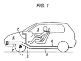
- Fig. 1 shows schematically a structure for a front part of an automotive vehicle to which the invention is applied.
- the illustrated structure for the front part of the automotive vehicle body comprises front side frames 2 extending longitudinally above a front axle 1, inclined forwardly upwardly intermediate frames 5 connecting rear ends of the front side frames 2 to front ends of floor frames 4 extending longitudinally underneath a floor of a passenger compartment 3, and a dash panel 7 separating the passenger compartment 3 from an engine compartment 6.
- the dash panel 7 extends upwardly from intermediate portions 5 which are located between the respective connecting portions of the front side frames 2 and floor frames 4. A lower edge of the dash panel 7 is connected to a floor panel 8 provided so as to extend from rear upper surfaces of the intermediate frames 5 to upper surfaces of the floor frames 4.
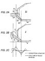
- FIG. 2A a conventional structure in which rear ends of front side frames 21 abut against a vertical plane of a dash panel 71, connecting points Al between the front side frames 21 and intermediate frames 51 are located at positions in the vicinity of the dash panel 71.
- a bending moment is applied to the front side frames 2 and the intermediate frames 5 by virtue of a load generated in the longitudinal direction of the vehicle body when the vehicle comes into a frontal collision
- a bending moment diagram around a Y axis becomes as shown by a broken line in Fig. 2C, whereby large peaks are generated at the respective connecting points A1, B1 between the intermediate frames 51 and the front side frames 21 and the floor frames 41.
- the inclined angle ⁇ of the intermediate frame 5 relative to the horizontal plane can be reduced by locating the connecting point A2 between the front side frame 2 and the intermediate frame 5 forward further than the conventional structure, as shown by a solid line in Fig. 2C, the peak of the bending moment can also be reduced. This, of course, contributes largely to reducing further the deformation amount of the passenger compartment 3.
- the construction described can largely contribute to the realization of the compatibility of a reduction in vehicle weight and the protection of the passenger compartment at an enhanced level.
Landscapes
- Engineering & Computer Science (AREA)
- Chemical & Material Sciences (AREA)
- Combustion & Propulsion (AREA)
- Transportation (AREA)
- Mechanical Engineering (AREA)
- Body Structure For Vehicles (AREA)
Applications Claiming Priority (2)
| Application Number | Priority Date | Filing Date | Title |
|---|---|---|---|
| JP13659499 | 1999-05-18 | ||
| JP13659499A JP3246900B2 (ja) | 1999-05-18 | 1999-05-18 | 自動車の前部車体構造 |
Publications (3)
| Publication Number | Publication Date |
|---|---|
| EP1055588A2 true EP1055588A2 (de) | 2000-11-29 |
| EP1055588A3 EP1055588A3 (de) | 2001-01-10 |
| EP1055588B1 EP1055588B1 (de) | 2004-03-10 |
Family
ID=15178958
Family Applications (1)
| Application Number | Title | Priority Date | Filing Date |
|---|---|---|---|
| EP00304213A Expired - Lifetime EP1055588B1 (de) | 1999-05-18 | 2000-05-18 | Vorderbau einer Kraftfahrzeugkarosserie |
Country Status (5)
| Country | Link |
|---|---|
| US (1) | US6435603B1 (de) |
| EP (1) | EP1055588B1 (de) |
| JP (1) | JP3246900B2 (de) |
| CN (1) | CN1104354C (de) |
| DE (1) | DE60008813T2 (de) |
Families Citing this family (8)
| Publication number | Priority date | Publication date | Assignee | Title |
|---|---|---|---|---|
| JP4010169B2 (ja) * | 2002-04-09 | 2007-11-21 | 三菱自動車工業株式会社 | 車体構造 |
| US7680688B2 (en) * | 2002-05-28 | 2010-03-16 | American Express Travel Related Services Company, Inc. | System and method for exchanging loyalty points for acquisitions |
| US6767050B2 (en) * | 2002-12-17 | 2004-07-27 | Ford Global Technologies, Llc | Passenger compartment isolator system for automotive vehicle |
| JP4051011B2 (ja) * | 2003-08-26 | 2008-02-20 | 本田技研工業株式会社 | 車体構造 |
| JP4329469B2 (ja) * | 2003-09-29 | 2009-09-09 | マツダ株式会社 | 車両の前部車体構造 |
| JP4900262B2 (ja) * | 2007-06-18 | 2012-03-21 | 日産自動車株式会社 | 車体前部構造 |
| JP6020944B2 (ja) | 2013-07-02 | 2016-11-02 | 本田技研工業株式会社 | 自動車の車体構造 |
| DE102016104568A1 (de) * | 2016-03-14 | 2017-09-14 | Teamobility Gmbh | Fahrzeug mit einer Mittelsitzposition |
Family Cites Families (7)
| Publication number | Priority date | Publication date | Assignee | Title |
|---|---|---|---|---|
| JPH0544230Y2 (de) | 1987-07-10 | 1993-11-09 | ||
| JPH0750301Y2 (ja) * | 1989-09-30 | 1995-11-15 | マツダ株式会社 | 自動車の前部車体構造 |
| JP2652928B2 (ja) | 1994-10-17 | 1997-09-10 | 本田技研工業株式会社 | 自動車の車体構造 |
| JP3357201B2 (ja) * | 1994-10-19 | 2002-12-16 | 本田技研工業株式会社 | 自動車の車体前部構造 |
| JP3489277B2 (ja) * | 1995-07-17 | 2004-01-19 | トヨタ自動車株式会社 | 車両用制動装置 |
| JP3478459B2 (ja) | 1996-11-12 | 2003-12-15 | スズキ株式会社 | 自動車の車体前部構造 |
| JP3458674B2 (ja) * | 1997-10-09 | 2003-10-20 | 日産自動車株式会社 | フロントサイドメンバ根元部構造 |
-
1999
- 1999-05-18 JP JP13659499A patent/JP3246900B2/ja not_active Expired - Fee Related
-
2000
- 2000-05-17 US US09/572,783 patent/US6435603B1/en not_active Expired - Lifetime
- 2000-05-18 EP EP00304213A patent/EP1055588B1/de not_active Expired - Lifetime
- 2000-05-18 DE DE60008813T patent/DE60008813T2/de not_active Expired - Lifetime
- 2000-05-18 CN CN00108588A patent/CN1104354C/zh not_active Expired - Fee Related
Also Published As
| Publication number | Publication date |
|---|---|
| EP1055588B1 (de) | 2004-03-10 |
| CN1273927A (zh) | 2000-11-22 |
| JP3246900B2 (ja) | 2002-01-15 |
| JP2000326868A (ja) | 2000-11-28 |
| CN1104354C (zh) | 2003-04-02 |
| DE60008813T2 (de) | 2004-08-12 |
| US6435603B1 (en) | 2002-08-20 |
| EP1055588A3 (de) | 2001-01-10 |
| DE60008813D1 (de) | 2004-04-15 |
Similar Documents
| Publication | Publication Date | Title |
|---|---|---|
| CN101332837B (zh) | 车身结构 | |
| CN109649498B (zh) | 前车身加强结构 | |
| US5048888A (en) | Subassembly for the front and rear region of a motor vehicle | |
| EP1332949A2 (de) | Fahrzeugvorderwagenaufbau | |
| US20090195019A1 (en) | Automotive vehicle body structure | |
| US5042837A (en) | Rear axle support for passenger vehicle | |
| EP2143584A1 (de) | Struktur zur Fahrzeugkanistermontage | |
| EP1055588B1 (de) | Vorderbau einer Kraftfahrzeugkarosserie | |
| CN110920755A (zh) | 车辆的前部车身结构 | |
| JPH0930452A (ja) | 自動車用サイドシル補強構造 | |
| US10981604B2 (en) | Vehicle bulkhead structure | |
| JP2002120755A (ja) | 自動車の前部車体構造 | |
| JP2003191750A (ja) | ウインドシールドガラス支持構造 | |
| JP3622715B2 (ja) | 車体前部構造 | |
| EP1177968B1 (de) | Stossenergieabsorbierende Struktur für ein Kraftfahrzeug | |
| JP3182973B2 (ja) | フロントボデーの構造 | |
| US12134422B2 (en) | Vehicle front body structure | |
| JPH1159496A (ja) | サスペンションメンバ取付構造 | |
| KR100339221B1 (ko) | 자동차의 차체보강구조 | |
| JPH0995260A (ja) | 車両の前部車体構造 | |
| JP2000302058A (ja) | 車両用ピラー構造 | |
| EP2428432B1 (de) | Vorderseitenchassis einer Fahrzeugkarosserie | |
| JPH08310442A (ja) | 自動車のセンタピラー補強構造 | |
| JP7317076B2 (ja) | 車室前部構造 | |
| KR100308977B1 (ko) | 차량용대쉬로워맴버보강구조 |
Legal Events
| Date | Code | Title | Description |
|---|---|---|---|
| PUAI | Public reference made under article 153(3) epc to a published international application that has entered the european phase |
Free format text: ORIGINAL CODE: 0009012 |
|
| PUAL | Search report despatched |
Free format text: ORIGINAL CODE: 0009013 |
|
| AK | Designated contracting states |
Kind code of ref document: A2 Designated state(s): DE FR GB |
|
| AX | Request for extension of the european patent |
Free format text: AL;LT;LV;MK;RO;SI |
|
| AK | Designated contracting states |
Kind code of ref document: A3 Designated state(s): AT BE CH CY DE DK ES FI FR GB GR IE IT LI LU MC NL PT SE |
|
| AX | Request for extension of the european patent |
Free format text: AL;LT;LV;MK;RO;SI |
|
| 17P | Request for examination filed |
Effective date: 20010319 |
|
| AKX | Designation fees paid |
Free format text: DE FR GB |
|
| 17Q | First examination report despatched |
Effective date: 20030114 |
|
| REG | Reference to a national code |
Ref country code: GB Ref legal event code: FG4D |
|
| GRAP | Despatch of communication of intention to grant a patent |
Free format text: ORIGINAL CODE: EPIDOSNIGR1 |
|
| GRAS | Grant fee paid |
Free format text: ORIGINAL CODE: EPIDOSNIGR3 |
|
| GRAA | (expected) grant |
Free format text: ORIGINAL CODE: 0009210 |
|
| AK | Designated contracting states |
Kind code of ref document: B1 Designated state(s): DE FR GB |
|
| REF | Corresponds to: |
Ref document number: 60008813 Country of ref document: DE Date of ref document: 20040415 Kind code of ref document: P |
|
| ET | Fr: translation filed | ||
| PLBE | No opposition filed within time limit |
Free format text: ORIGINAL CODE: 0009261 |
|
| STAA | Information on the status of an ep patent application or granted ep patent |
Free format text: STATUS: NO OPPOSITION FILED WITHIN TIME LIMIT |
|
| 26N | No opposition filed |
Effective date: 20041213 |
|
| PGFP | Annual fee paid to national office [announced via postgrant information from national office to epo] |
Ref country code: FR Payment date: 20050526 Year of fee payment: 6 |
|
| PGFP | Annual fee paid to national office [announced via postgrant information from national office to epo] |
Ref country code: GB Payment date: 20060512 Year of fee payment: 7 |
|
| REG | Reference to a national code |
Ref country code: FR Ref legal event code: ST Effective date: 20070131 |
|
| GBPC | Gb: european patent ceased through non-payment of renewal fee |
Effective date: 20070518 |
|
| PG25 | Lapsed in a contracting state [announced via postgrant information from national office to epo] |
Ref country code: FR Free format text: LAPSE BECAUSE OF NON-PAYMENT OF DUE FEES Effective date: 20060531 |
|
| PG25 | Lapsed in a contracting state [announced via postgrant information from national office to epo] |
Ref country code: GB Free format text: LAPSE BECAUSE OF NON-PAYMENT OF DUE FEES Effective date: 20070518 |
|
| PGFP | Annual fee paid to national office [announced via postgrant information from national office to epo] |
Ref country code: DE Payment date: 20130515 Year of fee payment: 14 |
|
| REG | Reference to a national code |
Ref country code: DE Ref legal event code: R119 Ref document number: 60008813 Country of ref document: DE |
|
| REG | Reference to a national code |
Ref country code: DE Ref legal event code: R119 Ref document number: 60008813 Country of ref document: DE Effective date: 20141202 |
|
| PG25 | Lapsed in a contracting state [announced via postgrant information from national office to epo] |
Ref country code: DE Free format text: LAPSE BECAUSE OF NON-PAYMENT OF DUE FEES Effective date: 20141202 |