EP1055862A1 - Installation de remplissage d'un volume de conditionnement avec du gaz - Google Patents
Installation de remplissage d'un volume de conditionnement avec du gaz Download PDFInfo
- Publication number
- EP1055862A1 EP1055862A1 EP00400532A EP00400532A EP1055862A1 EP 1055862 A1 EP1055862 A1 EP 1055862A1 EP 00400532 A EP00400532 A EP 00400532A EP 00400532 A EP00400532 A EP 00400532A EP 1055862 A1 EP1055862 A1 EP 1055862A1
- Authority
- EP
- European Patent Office
- Prior art keywords
- valve
- valves
- network
- filling
- control unit
- Prior art date
- Legal status (The legal status is an assumption and is not a legal conclusion. Google has not performed a legal analysis and makes no representation as to the accuracy of the status listed.)
- Granted
Links
- 238000011049 filling Methods 0.000 title claims description 59
- 238000000034 method Methods 0.000 claims abstract description 40
- 238000012545 processing Methods 0.000 claims abstract description 12
- 238000009434 installation Methods 0.000 claims description 56
- 238000004806 packaging method and process Methods 0.000 claims description 30
- 238000005303 weighing Methods 0.000 claims description 14
- 238000005259 measurement Methods 0.000 claims description 8
- 238000013022 venting Methods 0.000 claims description 8
- 238000011144 upstream manufacturing Methods 0.000 claims description 4
- 239000007789 gas Substances 0.000 description 58
- 239000000203 mixture Substances 0.000 description 19
- 238000009826 distribution Methods 0.000 description 13
- IJGRMHOSHXDMSA-UHFFFAOYSA-N Atomic nitrogen Chemical compound N#N IJGRMHOSHXDMSA-UHFFFAOYSA-N 0.000 description 10
- 230000003750 conditioning effect Effects 0.000 description 9
- QVGXLLKOCUKJST-UHFFFAOYSA-N atomic oxygen Chemical compound [O] QVGXLLKOCUKJST-UHFFFAOYSA-N 0.000 description 7
- 239000001301 oxygen Substances 0.000 description 7
- 229910052760 oxygen Inorganic materials 0.000 description 7
- 239000000523 sample Substances 0.000 description 6
- HSFWRNGVRCDJHI-UHFFFAOYSA-N Acetylene Chemical compound C#C HSFWRNGVRCDJHI-UHFFFAOYSA-N 0.000 description 5
- 230000001276 controlling effect Effects 0.000 description 5
- 229910052757 nitrogen Inorganic materials 0.000 description 5
- 230000001105 regulatory effect Effects 0.000 description 4
- 239000002904 solvent Substances 0.000 description 4
- 230000033228 biological regulation Effects 0.000 description 3
- 230000001143 conditioned effect Effects 0.000 description 3
- 125000002534 ethynyl group Chemical group [H]C#C* 0.000 description 3
- 238000003860 storage Methods 0.000 description 3
- CSCPPACGZOOCGX-UHFFFAOYSA-N Acetone Chemical compound CC(C)=O CSCPPACGZOOCGX-UHFFFAOYSA-N 0.000 description 2
- 230000005291 magnetic effect Effects 0.000 description 2
- 238000004458 analytical method Methods 0.000 description 1
- 238000004422 calculation algorithm Methods 0.000 description 1
- 125000004122 cyclic group Chemical group 0.000 description 1
- 235000021183 entrée Nutrition 0.000 description 1
- 230000009975 flexible effect Effects 0.000 description 1
- 238000007667 floating Methods 0.000 description 1
- 238000011010 flushing procedure Methods 0.000 description 1
- 230000010365 information processing Effects 0.000 description 1
- 239000007788 liquid Substances 0.000 description 1
- 239000000463 material Substances 0.000 description 1
- 238000002156 mixing Methods 0.000 description 1
- 238000012546 transfer Methods 0.000 description 1
Images


Classifications
-
- F—MECHANICAL ENGINEERING; LIGHTING; HEATING; WEAPONS; BLASTING
- F17—STORING OR DISTRIBUTING GASES OR LIQUIDS
- F17C—VESSELS FOR CONTAINING OR STORING COMPRESSED, LIQUEFIED OR SOLIDIFIED GASES; FIXED-CAPACITY GAS-HOLDERS; FILLING VESSELS WITH, OR DISCHARGING FROM VESSELS, COMPRESSED, LIQUEFIED, OR SOLIDIFIED GASES
- F17C5/00—Methods or apparatus for filling containers with liquefied, solidified, or compressed gases under pressures
- F17C5/002—Automated filling apparatus
-
- B—PERFORMING OPERATIONS; TRANSPORTING
- B01—PHYSICAL OR CHEMICAL PROCESSES OR APPARATUS IN GENERAL
- B01F—MIXING, e.g. DISSOLVING, EMULSIFYING OR DISPERSING
- B01F23/00—Mixing according to the phases to be mixed, e.g. dispersing or emulsifying
- B01F23/10—Mixing gases with gases
- B01F23/19—Mixing systems, i.e. flow charts or diagrams; Arrangements, e.g. comprising controlling means
-
- F—MECHANICAL ENGINEERING; LIGHTING; HEATING; WEAPONS; BLASTING
- F17—STORING OR DISTRIBUTING GASES OR LIQUIDS
- F17C—VESSELS FOR CONTAINING OR STORING COMPRESSED, LIQUEFIED OR SOLIDIFIED GASES; FIXED-CAPACITY GAS-HOLDERS; FILLING VESSELS WITH, OR DISCHARGING FROM VESSELS, COMPRESSED, LIQUEFIED, OR SOLIDIFIED GASES
- F17C2205/00—Vessel construction, in particular mounting arrangements, attachments or identifications means
- F17C2205/03—Fluid connections, filters, valves, closure means or other attachments
- F17C2205/0302—Fittings, valves, filters, or components in connection with the gas storage device
- F17C2205/0323—Valves
- F17C2205/0326—Valves electrically actuated
-
- F—MECHANICAL ENGINEERING; LIGHTING; HEATING; WEAPONS; BLASTING
- F17—STORING OR DISTRIBUTING GASES OR LIQUIDS
- F17C—VESSELS FOR CONTAINING OR STORING COMPRESSED, LIQUEFIED OR SOLIDIFIED GASES; FIXED-CAPACITY GAS-HOLDERS; FILLING VESSELS WITH, OR DISCHARGING FROM VESSELS, COMPRESSED, LIQUEFIED, OR SOLIDIFIED GASES
- F17C2205/00—Vessel construction, in particular mounting arrangements, attachments or identifications means
- F17C2205/05—Vessel or content identifications, e.g. labels
- F17C2205/054—Vessel or content identifications, e.g. labels by bar codes
-
- F—MECHANICAL ENGINEERING; LIGHTING; HEATING; WEAPONS; BLASTING
- F17—STORING OR DISTRIBUTING GASES OR LIQUIDS
- F17C—VESSELS FOR CONTAINING OR STORING COMPRESSED, LIQUEFIED OR SOLIDIFIED GASES; FIXED-CAPACITY GAS-HOLDERS; FILLING VESSELS WITH, OR DISCHARGING FROM VESSELS, COMPRESSED, LIQUEFIED, OR SOLIDIFIED GASES
- F17C2221/00—Handled fluid, in particular type of fluid
- F17C2221/01—Pure fluids
- F17C2221/011—Oxygen
-
- F—MECHANICAL ENGINEERING; LIGHTING; HEATING; WEAPONS; BLASTING
- F17—STORING OR DISTRIBUTING GASES OR LIQUIDS
- F17C—VESSELS FOR CONTAINING OR STORING COMPRESSED, LIQUEFIED OR SOLIDIFIED GASES; FIXED-CAPACITY GAS-HOLDERS; FILLING VESSELS WITH, OR DISCHARGING FROM VESSELS, COMPRESSED, LIQUEFIED, OR SOLIDIFIED GASES
- F17C2221/00—Handled fluid, in particular type of fluid
- F17C2221/01—Pure fluids
- F17C2221/014—Nitrogen
-
- F—MECHANICAL ENGINEERING; LIGHTING; HEATING; WEAPONS; BLASTING
- F17—STORING OR DISTRIBUTING GASES OR LIQUIDS
- F17C—VESSELS FOR CONTAINING OR STORING COMPRESSED, LIQUEFIED OR SOLIDIFIED GASES; FIXED-CAPACITY GAS-HOLDERS; FILLING VESSELS WITH, OR DISCHARGING FROM VESSELS, COMPRESSED, LIQUEFIED, OR SOLIDIFIED GASES
- F17C2221/00—Handled fluid, in particular type of fluid
- F17C2221/01—Pure fluids
- F17C2221/018—Acetylene
-
- F—MECHANICAL ENGINEERING; LIGHTING; HEATING; WEAPONS; BLASTING
- F17—STORING OR DISTRIBUTING GASES OR LIQUIDS
- F17C—VESSELS FOR CONTAINING OR STORING COMPRESSED, LIQUEFIED OR SOLIDIFIED GASES; FIXED-CAPACITY GAS-HOLDERS; FILLING VESSELS WITH, OR DISCHARGING FROM VESSELS, COMPRESSED, LIQUEFIED, OR SOLIDIFIED GASES
- F17C2221/00—Handled fluid, in particular type of fluid
- F17C2221/03—Mixtures
-
- F—MECHANICAL ENGINEERING; LIGHTING; HEATING; WEAPONS; BLASTING
- F17—STORING OR DISTRIBUTING GASES OR LIQUIDS
- F17C—VESSELS FOR CONTAINING OR STORING COMPRESSED, LIQUEFIED OR SOLIDIFIED GASES; FIXED-CAPACITY GAS-HOLDERS; FILLING VESSELS WITH, OR DISCHARGING FROM VESSELS, COMPRESSED, LIQUEFIED, OR SOLIDIFIED GASES
- F17C2223/00—Handled fluid before transfer, i.e. state of fluid when stored in the vessel or before transfer from the vessel
- F17C2223/01—Handled fluid before transfer, i.e. state of fluid when stored in the vessel or before transfer from the vessel characterised by the phase
- F17C2223/0107—Single phase
- F17C2223/0123—Single phase gaseous, e.g. CNG, GNC
-
- F—MECHANICAL ENGINEERING; LIGHTING; HEATING; WEAPONS; BLASTING
- F17—STORING OR DISTRIBUTING GASES OR LIQUIDS
- F17C—VESSELS FOR CONTAINING OR STORING COMPRESSED, LIQUEFIED OR SOLIDIFIED GASES; FIXED-CAPACITY GAS-HOLDERS; FILLING VESSELS WITH, OR DISCHARGING FROM VESSELS, COMPRESSED, LIQUEFIED, OR SOLIDIFIED GASES
- F17C2223/00—Handled fluid before transfer, i.e. state of fluid when stored in the vessel or before transfer from the vessel
- F17C2223/03—Handled fluid before transfer, i.e. state of fluid when stored in the vessel or before transfer from the vessel characterised by the pressure level
- F17C2223/036—Very high pressure (>80 bar)
-
- F—MECHANICAL ENGINEERING; LIGHTING; HEATING; WEAPONS; BLASTING
- F17—STORING OR DISTRIBUTING GASES OR LIQUIDS
- F17C—VESSELS FOR CONTAINING OR STORING COMPRESSED, LIQUEFIED OR SOLIDIFIED GASES; FIXED-CAPACITY GAS-HOLDERS; FILLING VESSELS WITH, OR DISCHARGING FROM VESSELS, COMPRESSED, LIQUEFIED, OR SOLIDIFIED GASES
- F17C2250/00—Accessories; Control means; Indicating, measuring or monitoring of parameters
- F17C2250/03—Control means
- F17C2250/032—Control means using computers
-
- F—MECHANICAL ENGINEERING; LIGHTING; HEATING; WEAPONS; BLASTING
- F17—STORING OR DISTRIBUTING GASES OR LIQUIDS
- F17C—VESSELS FOR CONTAINING OR STORING COMPRESSED, LIQUEFIED OR SOLIDIFIED GASES; FIXED-CAPACITY GAS-HOLDERS; FILLING VESSELS WITH, OR DISCHARGING FROM VESSELS, COMPRESSED, LIQUEFIED, OR SOLIDIFIED GASES
- F17C2250/00—Accessories; Control means; Indicating, measuring or monitoring of parameters
- F17C2250/04—Indicating or measuring of parameters as input values
- F17C2250/0404—Parameters indicated or measured
- F17C2250/0439—Temperature
-
- F—MECHANICAL ENGINEERING; LIGHTING; HEATING; WEAPONS; BLASTING
- F17—STORING OR DISTRIBUTING GASES OR LIQUIDS
- F17C—VESSELS FOR CONTAINING OR STORING COMPRESSED, LIQUEFIED OR SOLIDIFIED GASES; FIXED-CAPACITY GAS-HOLDERS; FILLING VESSELS WITH, OR DISCHARGING FROM VESSELS, COMPRESSED, LIQUEFIED, OR SOLIDIFIED GASES
- F17C2250/00—Accessories; Control means; Indicating, measuring or monitoring of parameters
- F17C2250/04—Indicating or measuring of parameters as input values
- F17C2250/0404—Parameters indicated or measured
- F17C2250/0447—Composition; Humidity
- F17C2250/046—Humidity
-
- F—MECHANICAL ENGINEERING; LIGHTING; HEATING; WEAPONS; BLASTING
- F17—STORING OR DISTRIBUTING GASES OR LIQUIDS
- F17C—VESSELS FOR CONTAINING OR STORING COMPRESSED, LIQUEFIED OR SOLIDIFIED GASES; FIXED-CAPACITY GAS-HOLDERS; FILLING VESSELS WITH, OR DISCHARGING FROM VESSELS, COMPRESSED, LIQUEFIED, OR SOLIDIFIED GASES
- F17C2250/00—Accessories; Control means; Indicating, measuring or monitoring of parameters
- F17C2250/04—Indicating or measuring of parameters as input values
- F17C2250/0486—Indicating or measuring characterised by the location
- F17C2250/0491—Parameters measured at or inside the vessel
-
- F—MECHANICAL ENGINEERING; LIGHTING; HEATING; WEAPONS; BLASTING
- F17—STORING OR DISTRIBUTING GASES OR LIQUIDS
- F17C—VESSELS FOR CONTAINING OR STORING COMPRESSED, LIQUEFIED OR SOLIDIFIED GASES; FIXED-CAPACITY GAS-HOLDERS; FILLING VESSELS WITH, OR DISCHARGING FROM VESSELS, COMPRESSED, LIQUEFIED, OR SOLIDIFIED GASES
- F17C2250/00—Accessories; Control means; Indicating, measuring or monitoring of parameters
- F17C2250/06—Controlling or regulating of parameters as output values
- F17C2250/0605—Parameters
- F17C2250/0626—Pressure
-
- F—MECHANICAL ENGINEERING; LIGHTING; HEATING; WEAPONS; BLASTING
- F17—STORING OR DISTRIBUTING GASES OR LIQUIDS
- F17C—VESSELS FOR CONTAINING OR STORING COMPRESSED, LIQUEFIED OR SOLIDIFIED GASES; FIXED-CAPACITY GAS-HOLDERS; FILLING VESSELS WITH, OR DISCHARGING FROM VESSELS, COMPRESSED, LIQUEFIED, OR SOLIDIFIED GASES
- F17C2250/00—Accessories; Control means; Indicating, measuring or monitoring of parameters
- F17C2250/06—Controlling or regulating of parameters as output values
- F17C2250/0605—Parameters
- F17C2250/0636—Flow or movement of content
-
- F—MECHANICAL ENGINEERING; LIGHTING; HEATING; WEAPONS; BLASTING
- F17—STORING OR DISTRIBUTING GASES OR LIQUIDS
- F17C—VESSELS FOR CONTAINING OR STORING COMPRESSED, LIQUEFIED OR SOLIDIFIED GASES; FIXED-CAPACITY GAS-HOLDERS; FILLING VESSELS WITH, OR DISCHARGING FROM VESSELS, COMPRESSED, LIQUEFIED, OR SOLIDIFIED GASES
- F17C2270/00—Applications
- F17C2270/02—Applications for medical applications
-
- F—MECHANICAL ENGINEERING; LIGHTING; HEATING; WEAPONS; BLASTING
- F17—STORING OR DISTRIBUTING GASES OR LIQUIDS
- F17C—VESSELS FOR CONTAINING OR STORING COMPRESSED, LIQUEFIED OR SOLIDIFIED GASES; FIXED-CAPACITY GAS-HOLDERS; FILLING VESSELS WITH, OR DISCHARGING FROM VESSELS, COMPRESSED, LIQUEFIED, OR SOLIDIFIED GASES
- F17C2270/00—Applications
- F17C2270/05—Applications for industrial use
-
- F—MECHANICAL ENGINEERING; LIGHTING; HEATING; WEAPONS; BLASTING
- F17—STORING OR DISTRIBUTING GASES OR LIQUIDS
- F17C—VESSELS FOR CONTAINING OR STORING COMPRESSED, LIQUEFIED OR SOLIDIFIED GASES; FIXED-CAPACITY GAS-HOLDERS; FILLING VESSELS WITH, OR DISCHARGING FROM VESSELS, COMPRESSED, LIQUEFIED, OR SOLIDIFIED GASES
- F17C2270/00—Applications
- F17C2270/05—Applications for industrial use
- F17C2270/059—Mass bottling, e.g. merry belts
Definitions
- Pure gases or gas mixtures are commonly conditioned in bottles or frames carrying a batch of bottles. These are filled in a filling facility and then transported to the site use of gas.
- filling installations conventionally include a network of valves allowing selective connection to the packaging volume to fill a variety of supply gas sources.
- opening and closing valves are entrusted to an operator. This one opens and closes the different valves, at determined times, and following a sequence determined. The operation of such an installation therefore requires the continuous presence of an experienced operator who determines the sequence operations.
- control unit is adapted to receive, at input, the specification of the gas to be introduced into the volume conditioning.
- the information entered consists in particular of the composition in mass, or in pressure of the various bodies constituting the gas.
- the information entered in the control unit is the expected result of the filling operation.
- the document FR-A-2.713.105 describes an installation filling a tank with a mixture of gases.
- This installation includes a computer controlling the cyclic opening and closing of valves arranged between the tank and pressurized gas sources.
- the computer receives the expected composition for mixing as a set point. It is suitable for determining and implementing a piloting cycle different valves in order to obtain the desired mixture.
- JP-2675633 describes an installation for filling cylinders with several gas sources which can selectively supply bottles under the control of a control unit. The operating steps of the control unit and the variables entered are not described.
- the object of the invention is to provide a simple filling installation. allowing uniformity and standardization of installations filling systems used on several sites, thus facilitating filling packaging volumes, while improving reproducibility and reliability of gas conditioning operations.
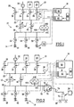
- the installation shown in Figure 1 includes, like any installation filling according to the invention, a set 10 of sources of supply gas and a network 12 of controlled valves, selectively connecting the outlet of each supply gas source, to a set 14 of fittings constituting connection points for packaging bottles. It also includes a unit 16 for controlling the network of valves 12.
- an oxygen storage 18 and a storage of nitrogen 20 are provided at the inlet of the valve network 12. These sources of gases are connected to a main supply line 22 through controlled valves 24 and 26.
- the main supply line 22 is connected to an outlet 28 of venting via a controlled valve 30.
- a vacuum pump 32 is connected to the main line supply 22 via a controlled valve 34.
- valves 24, 26, 30, 34 allowing the selective connection of the main supply line 22 to a gas source, at the outlet of vent 28 or vacuum pump 32, are controlled from the piloting 16.
- a supply pressure sensor 36 is mounted on the pipe main supply 22. This pressure sensor is connected to the control unit 16.
- the main supply line 22 is connected to a line main distribution 28 via a shut-off valve 40 and a control valve 42. These two valves 40, 42 are mounted in parallel and are controlled from the control unit 16. They regulate the filling rate of the bottles
- pressure sensors 44A, 44B, 44C On the distribution line 38 are provided three pressure sensors 44A, 44B, 44C having measuring ranges of 300 respectively bars, 40 bars and 5 bars. These pressure sensors are connected to the control unit 16 in order to communicate to the latter the pressure in the distribution 38.
- the set of points 14 for connecting the bottles are distributed along three ramps 46, 48, 50.
- Each ramp generally has sixteen connection points, each suitable for connecting a 50-liter bottle.
- the ramps 46, 48, 50 are connected in parallel to the distribution pipe 38 via a controlled sectioning valve 52, 54, 56 specific to each ramp. These valves are connected for their control to the control unit 16.
- an infrared probe 58 for measuring the temperature is provided. in the vicinity of the ramp 50.
- the probe 58 is connected to the control unit 16. It is suitable to be applied to a bottle and to measure the filling temperature of this bottle.
- the temperature measured by the probe 58 allows the control unit 16 to correct the target pressures as a function of the temperature, in order to to fill the bottles to a desired pressure in standard temperature conditions.
- control unit 16 comprises means 60 input of a recipe for filling a batch of sixteen bottles with a mixture of gases whose nature conforms to a given specification.
- Each recipe consists of a sequence of successive procedures.
- Each procedure describes a basic task that can be put implemented by the valve assembly under the control of the control unit 16.
- Each procedure is characterized by the designation of a valve, and information relating to the mode of control of the operation.
- this information first includes the actuation mode of the valve, the instruction to be reached which conditions the stopping of the actuation of the valve, the tolerance applicable to the percentage setpoint and the delay wait in seconds between completion of valve actuation and the start of actuation of the next valve.
- the recipes are established manually by transcribing with the defined formalism above, the successive elementary steps implemented by an operator.
- the recipes are established by processing means of information receiving as input the desired characteristics for the gas filling the bottles.
- the information processing means determine the sequence of procedures making up the recipe.
- This recipe is stored on a support allowing its implementation subsequent by an installation according to the invention.
- the control unit 16 is for example made up of an industrial computer or a programmable controller implementing a program adapted.
- the means 60 for entering a recipe include for example a barcode reader.
- the recipes are presented on a material support, such as a sheet of paper in the form of a succession of barcodes.
- a material support such as a sheet of paper in the form of a succession of barcodes.
- Each barcode advantageously corresponds to a recipe procedure.
- the recipes are stored on magnetic media, such as floppy disks.
- the input means 60 then comprise a reader suitable for magnetic media.
- the input means 60 comprise a connection to a local data transfer network, allowing sending recipes from a remote station to the control unit 16.
- control unit 16 includes means 62 for processing successive procedures constituting the recipe entered. These are suitable for controlling the network of valves 12 for the sequential implementation of the elementary tasks described in the sequence of procedures constituting the recipe. Each controlled valves is connected to the processing means 62.
- the means 62 for processing the procedures include a time delay adapted to postpone, by a specified waiting period, the implementation of the following elementary task, after the end of the actuation of the valve designated in the current procedure.
- the control unit 16 further comprises means 64 for collecting measurements made by the various sensors of the installation. These collection means are connected to means 62 for processing procedures successive so that the latter put an end to the actuation of a valve selected when the measurement made by a sensor reaches a setpoint.
- Table 1 describes by way of example the recipe for filling sixteen bottles with a volume of 50 liters with medical oxygen under a pressure of 201 bars absolute at 15 ° C with ⁇ 15%.
- the recipe presented here includes six procedures, each described by a line in the table.
- the first procedure implemented consists in venting the bottles by opening the vent valve 30, in order to ensure a pressure drop down to a pressure of 1.5 bar absolute ⁇ 20%. Once this pressure is reached, the vent valve 30 is closed. After a waiting time of one second, the vacuum valve 34 is open to ensure a descent of the pressure up to a setpoint of 0.20 bar absolute ⁇ 20%. After this pressure has been reached and after a waiting period of one second has expired, the oxygen inlet valve 24 is open to ensure a rise in cylinder pressure up to a pressure of 5 bar absolute ⁇ 20%.
- valve vent 30 is open until the pressure in the line distribution 38 reaches a set pressure value equal to 1.5 bar absolute ⁇ 20%.
- the distribution line 38 is put under vacuum by opening the vacuum valve 34 until the pressure down to a set pressure of 0.2 bar absolute ⁇ 20%.
- the oxygen supply valve 24 is then opened again until what the pressure in the distribution line 38 and therefore in the bottles reaches 201 bars absolute ⁇ 5%.
- each ramp is connected in parallel to the outlet of the valve network 12 through a clean valve 52, 54, 56.
- a clean valve 52, 54, 56 is connected to the outlet of the valve network 12 through a clean valve 52, 54, 56.
- a batch of sixteen bottles is filled on one of the ramps
- a another batch to be filled is installed on a second ramp, while a third lot of bottles, previously filled, is detached from the third ramp.
- the shut-off valve associated with this ramp is open, while the valves of the other ramps are kept closed, allowing intervention on the bottles.
- the installation can therefore fill bottles almost continuously.
- shut-off valve 40 mounted in parallel with the shut-off valve regulation 42 ensures a bypass of the gas flow when the flow gas is maximum, the control valve then being inoperative. On the contrary, for small flows, which must be precisely regulated, the bypass 40 is closed and most of the flow passes through the control valve 42.
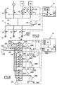
- the filling installation of figure 2 is intended for packaging mixtures of compressed gases as a function of the corrected pressure by the temperature and the weighing of a pilot bottle.
- a bypass is provided on the distribution pipe 38. 70 to which a pilot bottle 72 is connected. This bottle is connected at the end of a hose 74.
- the branch 70 includes a valve 76 and a block valve 78 mounted in bypass. These valves 76 and 78 are controlled by the control unit 16.
- a scale 80 is provided to ensure continuous weighing of the pilot bottle 72.
- the balance 80 is connected to the control unit 16.
- the temperature probe 58 is deported in the immediate vicinity of the pilot bottle 72, in order to determine the temperature of the gas contained in this one.
- Table 2 describes, by way of example, the recipe for filling sixteen bottles with a volume of 50 liters with a mixture of medical air consisting of 20% oxygen and 80% nitrogen with a difference 5% at a pressure of 201 bar absolute.
- the recipe presented here includes seven procedures, each described by a line in the table.
- the first procedure implemented consists in carrying out a air from the bottles by opening the vent valve 30 so ensure a drop in pressure to a pressure of 1.5 bar absolute ⁇ 20%. Once this pressure is reached, the vent valve 30 is closed. After a waiting period of one second, the vacuum valve 34 is open to ensure pressure drop to a set point from 0.20 bar absolute ⁇ 20%. After this pressure has been reached and after a waiting period of one second has expired, the inlet valve of nitrogen 26 is opened to ensure a pressure rise in the bottles up to a pressure of 5 bar absolute ⁇ 20%.
- valve vent 30 is open until the pressure in the line distribution 38 reaches a set pressure value equal to 1.5 bar absolute ⁇ 20%.
- the distribution line 38 is put under vacuum by opening the vacuum valve 34 until the pressure drops to a set pressure of 0.2 bar absolute ⁇ 20%.
- the oxygen supply valve 24 is then opened until the mass of the pilot bottle 72, determined by the scale 80, reaches 2.633 kg ⁇ 5%.
- valve 26 nitrogen inlet is open until the mass of one of the bottles reaches 9.294 kg ⁇ 5%.
- the filling installation of Figure 3 is intended for packaging mixtures of compressed gases as a function of the corrected pressure by the temperature and the weighing of the entire batch of bottles to be packaged.
- the installation includes a single conditioning ramp 100 to which all sixteen bottles 102 of a batch are connected fill.
- the conditioning ramp 100 is connected by a hose 104 to the main supply line 22.
- a control valve 106 mounted in parallel with a control valve sectioning 108.
- the valves 106 and 108 are connected for their control to the control unit 16.
- the pressure sensors 44A, 44B, 44C are mounted directly on the conditioning ramp 100.
- a balance 110 suitable for continuously weighing all the bottles 102 of the batch to be packaged are connected to the piloting 16.
- the temperature probe 58 is deported to the immediate vicinity of the batch of bottles 102.
- hose 104 allows the result of the weighing carried out by the scale 110 is not influenced by the rigidity of the ramp packaging 100, since the latter is floating and is not supported only by the bottles 102 alone.
- FIG. 4 shows a filling installation for the compressed gas mixture conditioning regulated according to the pressure corrected by temperature and by weighing one of the bottles in the batch to condition.
- FIG. 4 is substantially similar to that of FIG. 1. It further comprises a balance 120 adapted for weigh one, denoted 122, of the bottles connected to the filling ramp 50.
- the balance 120 is connected to the control unit 16.
- the temperature probe 58 is applied to the bottle 122.
- FIG. 5 The installation of FIG. 5 is intended for the conditioning of a gas unique with pressure regulation corrected by gas temperature.
- the installation is substantially similar to that of the figure 1.
- the bypass 40 and regulation 42 valves are eliminated.
- the valves 24 and 26, provided at the outlet of the sources of gases 18 and 20, are replaced by proportional valves 130, 132, controlled by the control unit 16.
- proportional valves 130, 132 are replaced by proportional valves 130, 132, controlled by the control unit 16.
- pressure sensors 134,136 connected to the control unit 16 in order to communicate the gas pressures feed.
- the flow rate of the supply gases is regulated not between the main supply line 22 and the supply line distribution 38, but directly at the outlet of gas sources 18 and 20 by through proportional valves 130, 132.
- FIGS. 4 and 5 operate by implementation a recipe made up of procedures defining the opening sequence and valve closures based on comparison of measurements collected by the sensors with the instructions defined in the procedures.
- Figure 6 The installation of Figure 6 is intended for gas conditioning liquefied regulated by weighing the liquefied gas, with rinsing of the bottles. The rinsing operations are carried out under pressure corrected by temperature.
- a phase of conditioning a gas includes a step initial rinsing of the bottle followed by a proper filling step said.
- the recipe defines a first rinsing step then a second filling step, the rinsing and filling steps each consisting of a sequence of procedures.
- FIG. 6 The installation of Figure 6 has three filling stations 200A, 200B, 200C identical and mounted in parallel.
- Each filling station has its own network of valves noted 202A, 202B, 202C.
- the valves of each network have their output connected to a line 204A, 204B, 204C intended for the connection of a cylinder to fill.
- These lines are each provided with a pressure sensor 206A, 2066, 206C connected to the control unit 16.
- Each valve network 202A, 202B, 202C includes a valve 210 vacuum system ensuring the selective connection of the bottles with a common vacuum pump 212.
- each valve network includes a valve 214 controlling a venting outlet 216.
- a valve 218 for controlling the supply gas is provided in each valve network. Upstream of the supply gas valves 218 is mounted a common control valve 220 disposed at the outlet of a source 222 of filling gas, such as liquid CO 2 . A pressure sensor 224, connected to the control unit 16, is provided at the outlet from the filling gas source 222.
- each valve network includes a valve 226 rinse ordering the connection of each bottle with a source flushing gas common 228.
- each valve network includes an analysis valve 230 ensuring the selective connection of the bottle with a humidity analyzer common 232, the latter being connected to the control unit 16.
- Balances 234A, 234B, 234C are provided at each station filling to continuously weigh the bottles.
- the initial rinsing and filling steps are carried out under the control of the piloting unit by implementing for each stage a succession of elementary tasks each defined by a procedure.
- Figure 7 is shown a solvent redosing installation of an acetylene bottle and control of the charge of that bottle after filling.
- It comprises a source of solvent 300 such as acetone supplying, through a proportional valve 302, a distribution line 304.
- a pressure sensor 305 is provided downstream of the source of solvent 300.
- Distribution line 304 has two branches supplying each a bottle to be filled, through a stop valve 306, 308.
- a pressure sensor 310, 312 is mounted at the outlet the corresponding stop valve.
- Valves 302, 306, 308 are controlled by the control unit 16 and the sensors 308, 310, 312 and the scales 314, 316 are connected to this same control unit.
- Two control bottles 320 are fitted with temperature sensors 322. One is placed inside a room while the other is arranged outside the room. Depending on the bottles to be redosed, and in particular their previous place of storage, namely inside a room or outside, one or other of the control bottles 320 is used as a reference temperature during redosage.
Landscapes
- Engineering & Computer Science (AREA)
- Chemical & Material Sciences (AREA)
- Chemical Kinetics & Catalysis (AREA)
- Mechanical Engineering (AREA)
- General Engineering & Computer Science (AREA)
- Filling Or Discharging Of Gas Storage Vessels (AREA)
- Agricultural Chemicals And Associated Chemicals (AREA)
Abstract
Description
- un ensemble de sources de gaz d'alimentation;
- au moins un raccord de liaison du ou de chaque volume de conditionnement;
- un réseau de vannes commandées, reliant sélectivement la sortie de chaque source de gaz d'alimentation au ou à chaque raccord ; et
- une unité de pilotage du réseau de vannes adaptée pour commander l'état des vannes pour le remplissage du ou de chaque volume de conditionnement avec un gaz conforme à la spécification donnée.
- un ensemble de sources de gaz d'alimentation;
- au moins un raccord de liaison du ou de chaque volume de conditionnement;
- un réseau de vannes commandées, reliant sélectivement la sortie de chaque source de gaz d'alimentation au ou à chaque raccord ; et
- une unité de pilotage du réseau de vannes adaptée pour commander l'état des vannes pour le remplissage du ou de chaque volume de conditionnement avec un gaz conforme à la spécification donnée;
- ladite unité de pilotage comporte des moyens d'entrée d'une recette
constituée d'une séquence de procédures, chaque procédure décrivant une
tâche élémentaire pouvant être mise en oeuvre par le réseau de vannes
sous la commande de l'unité de pilotage,
et en ce que ladite unité de pilotage comporte des moyens de traitement des procédures successives constituant la recette, lesquels moyens sont adaptés pour commander le réseau de vannes pour la mise en oeuvre séquentielle des tâches élémentaires décrites successivement dans la séquence de procédures constituant la recette.
- chaque procédure comporte la désignation d'une unique vanne devant être commandée dans le réseau de vannes, lors de la mise en oeuvre de la tâche élémentaire correspondante, et des informations relatives au mode d'actionnement de la vanne;
- les informations relatives au mode d'actionnement de chaque vanne comportent une valeur de consigne, l'installation comporte un ensemble de capteurs adaptés pour effectuer des mesures sur l'état de remplissage du ou de chaque volume de conditionnement, et les moyens de traitement sont adaptés pour mettre un terme à l'actionnement de la vanne lorsque la mesure effectuée atteint la valeur de consigne correspondante;
- l'ensemble de capteurs comporte au moins l'un parmi un capteur de mesure de la température du gaz dans au moins un volume de conditionnement, une balance de pesée d'au moins un volume de conditionnement, un capteur de pression disposé en amont d'au moins un volume de conditionnement, et un capteur d'humidité disposé en aval d'au moins un volume de conditionnement;
- les informations relatives au mode d'actionnement de la vanne comportent un délai d'attente, et en ce que les moyens de traitement comportent une temporisation adaptée pour différer, dudit délai d'attente, la mise en oeuvre de la tâche élémentaire suivante après la fin de l'actionnement de la vanne désignée dans la procédure en cours;
- elle comporte une pompe à vide et le réseau de vannes comporte des moyens pour relier sélectivement la pompe à vide au ou à chaque raccord sous la commande de ladite unité de pilotage mettant en oeuvre une tâche élémentaire de mise sous vide décrite dans la séquence de procédures constituant la recette;
- elle comporte une sortie de mise à l'air et le réseau de vannes comporte des moyens pour relier sélectivement la sortie de mise à l'air au ou à chaque raccord sous la commande de ladite unité de pilotage mettant en oeuvre une tâche élémentaire de mise à l'air décrite dans la séquence de procédure constituant la recette; et
- elle comporte au moins deux ensembles de raccords pour la liaison de volumes de conditionnement, lesquels ensembles de raccords sont reliés en parallèle à la sortie dudit réseau de vannes par l'intermédiaire d'une vanne de sectionnement propre à chaque ensemble de raccords.
- La figure 1 est une vue schématique d'une installation de remplissage de bouteilles avec un mélange de gaz comprimé, avec contrôle par la pression corrigée par la température;
- La figure 2 est une vue schématique d'une installation de remplissage de bouteilles avec un mélange de gaz comprimé, avec contrôle par la pression corrigée par la température et par la pesée d'une bouteille pilote;
- La figure 3 est une vue schématique d'une installation de remplissage d'un lot de bouteilles avec un mélange de gaz comprimé, avec contrôle par la pression corrigée par la température et par la pesée de la totalité du lot de bouteilles à conditionner;
- La figure 4 est une vue schématique d'une installation de remplissage d'un lot de bouteilles avec un mélange de gaz comprimé, avec contrôle par la pression corrigée par la température et par la pesée d'une des bouteilles du lot de bouteilles à conditionner;
- La figure 5 est une vue schématique d'une installation de remplissage de bouteilles avec un gaz pur, avec contrôle par la pression corrigée par la température de gaz pur;
- La figure 6 est une vue schématique d'une installation de remplissage de bouteilles avec un gaz pur liquéfié, avec contrôle par la pesée du gaz liquéfié et par la pression corrigée par la température avec rinçage initial des emballages ; et
- La figure 7 est une vue schématique d'une installation de redosage de bouteilles d'acétylène en solvant et contrôle de la charge d'acétylène des bouteilles après remplissage.



Claims (8)
- Installation de remplissage d'au moins un volume de conditionnement avec du gaz dont la nature est conforme à une spécification donnée, comportant :caractérisée en ce que :un ensemble de sources de gaz d'alimentation (18, 20 ; 222, 228 ; 300) ;au moins un raccord (14) de liaison du ou de chaque volume de conditionnement ;un réseau (12 ; 202A, 202B, 202C) de vannes commandées, reliant sélectivement la sortie de chaque source de gaz d'alimentation au ou à chaque raccord (14) ; etune unité (16) de pilotage du réseau de vannes adaptée pour commander l'état des vannes pour le remplissage du ou de chaque volume de conditionnement avec un gaz conforme à la spécification donnée ;ladite unité de pilotage (16) comporte des moyens (60) d'entrée d'une recette constituée d'une séquence de procédures, chaque procédure décrivant une tâche élémentaire pouvant être mise en oeuvre par le réseau de vannes sous la commande de l'unité de pilotage (16),
et en ce que ladite unité de pilotage (16) comporte des moyens (62) de traitement des procédures successives constituant la recette, lesquels moyens (62) sont adaptés pour commander le réseau de vannes (12) pour la mise en oeuvre séquentielle des tâches élémentaires décrites successivement dans la séquence de procédures constituant la recette. - Installation selon la revendication 1, caractérisée en ce que chaque procédure comporte la désignation d'une unique vanne devant être commandée dans le réseau (12) de vannes, lors de la mise en oeuvre de la tâche élémentaire correspondante, et des informations relatives au mode d'actionnement de la vanne.
- Installation selon la revendication 2, caractérisée en ce que les informations relatives au mode d'actionnement de chaque vanne comportent une valeur de consigne, en ce que l'installation comporte un ensemble de capteurs (36, 44A, 44B, 44C, 58 ; 80 ; 110 ; 120 ; 134, 136 ; 206A, 206B, 206C , 224, 234A, 234B , 234C ; 305, 310, 312, 314, 316) adaptés pour effectuer des mesures sur l'état de remplissage du ou de chaque volume de conditionnement, et en ce que les moyens de traitement (62) sont adaptés pour mettre un terme à l'actionnement de la vanne lorsque la mesure effectuée atteint la valeur de consigne correspondante.
- Installation selon la revendication 3, caractérisée en ce que l'ensemble de capteurs comporte au moins l'un parmi un capteur (58) de mesure de la température du gaz dans au moins un volume de conditionnement, une balance (80 ; 110 ; 120 ; 234A, 234B, 234C ; 314, 316) de pesée d'au moins un volume de conditionnement, un capteur (44A, 44B, 44C) de pression disposé en amont d'au moins un volume de conditionnement, et un capteur d'humidité (232) disposé en aval d'au moins un volume de conditionnement.
- Installation selon l'une quelconque des revendications 2, 3 ou 4, caractérisée en ce que les informations relatives au mode d'actionnement de la vanne comportent un délai d'attente, et en ce que les moyens de traitement (62) comportent une temporisation adaptée pour différer, dudit délai d'attente, la mise en oeuvre de la tâche élémentaire suivante après la fin de l'actionnement de la vanne désignée dans la procédure en cours.
- Installation de remplissage selon l'une quelconque des revendications précédentes, caractérisée en ce qu'elle comporte une pompe à vide (32) et le réseau de vannes (12) comporte des moyens pour relier sélectivement la pompe à vide (32) au ou à chaque raccord (14) sous la commande de ladite unité de pilotage (16) mettant en oeuvre une tâche élémentaire de mise sous vide décrite dans la séquence de procédures constituant la recette.
- Installation selon l'une quelconque des revendications précédentes, caractérisée en ce qu'elle comporte une sortie de mise à l'air (28) et le réseau de vannes (12) comporte des moyens pour relier sélectivement la sortie de mise à l'air (28) au ou à chaque raccord (14) sous la commande de ladite unité de pilotage (16) mettant en oeuvre une tâche élémentaire de mise à l'air décrite dans la séquence de procédure constituant la recette.
- Installation selon l'une quelconque des revendications précédentes, caractérisée en ce qu'elle comporte au moins deux ensembles de raccords (46, 48, 50) pour la liaison de volumes de conditionnement, lesquels ensembles de raccords (14) sont reliés en parallèle à la sortie dudit réseau de vannes (12) par l'intermédiaire d'une vanne de sectionnement (52, 54, 56) propre à chaque ensemble de raccords.
Applications Claiming Priority (2)
| Application Number | Priority Date | Filing Date | Title |
|---|---|---|---|
| FR9906651 | 1999-05-26 | ||
| FR9906651A FR2794216B1 (fr) | 1999-05-26 | 1999-05-26 | Installation de remplissage d'un volume de conditionnement avec du gaz |
Publications (2)
| Publication Number | Publication Date |
|---|---|
| EP1055862A1 true EP1055862A1 (fr) | 2000-11-29 |
| EP1055862B1 EP1055862B1 (fr) | 2008-10-29 |
Family
ID=9546022
Family Applications (1)
| Application Number | Title | Priority Date | Filing Date |
|---|---|---|---|
| EP00400532A Expired - Lifetime EP1055862B1 (fr) | 1999-05-26 | 2000-02-28 | Installation de remplissage d'un volume de conditionnement avec du gaz |
Country Status (9)
| Country | Link |
|---|---|
| US (1) | US6182713B1 (fr) |
| EP (1) | EP1055862B1 (fr) |
| JP (1) | JP2000337596A (fr) |
| AT (1) | ATE412848T1 (fr) |
| AU (1) | AU780042B2 (fr) |
| CA (1) | CA2290284C (fr) |
| DE (1) | DE60040632D1 (fr) |
| FR (1) | FR2794216B1 (fr) |
| ZA (1) | ZA997294B (fr) |
Cited By (3)
| Publication number | Priority date | Publication date | Assignee | Title |
|---|---|---|---|---|
| FR2915801A1 (fr) * | 2007-05-03 | 2008-11-07 | Taema Sa | Procede de controle d'un lot homogene de bouteilles de fluide sous pression |
| US8047079B2 (en) | 2007-05-03 | 2011-11-01 | L'air Liquide Societe Anonyme Pour L'etude Et Exploitation Des Procedes Georges Claude | Method for controlling an electronic pressure gauge and pressure gauge therefor |
| US8359171B2 (en) | 2007-05-03 | 2013-01-22 | L'air Liquide Societe Anonyme Pour L'etude Et L'exploitation Des Procedes Georges Claude | Electronic pressure gauge for measuring pressure |
Families Citing this family (13)
| Publication number | Priority date | Publication date | Assignee | Title |
|---|---|---|---|---|
| JP2003065495A (ja) * | 2001-08-28 | 2003-03-05 | Nippon Sanso Corp | 混合ガス充填方法とその装置 |
| US6655422B2 (en) | 2001-09-26 | 2003-12-02 | Atnl, Inc. | Computer controlled apparatus and method of filling cylinders with gas |
| US6827084B2 (en) * | 2002-06-21 | 2004-12-07 | Lloyd Thomas Grubb, Jr. | Automatic gas blender |
| US6823906B2 (en) * | 2002-08-16 | 2004-11-30 | Western International Gas & Cylinder Inc. | Acetylene distribution system |
| US20050076954A1 (en) * | 2003-10-08 | 2005-04-14 | Western International Gas & Cylinder Inc. | Acetylene cylinder manifold assembly |
| FR2884592B1 (fr) * | 2005-04-13 | 2007-08-03 | Air Liquide | Procede de controle du remplissage de bouteilles de gaz |
| US7337794B2 (en) * | 2005-10-05 | 2008-03-04 | Medra Arabia Trading | Method and apparatus for the delivery of compressed gas in the field |
| DE102006016554A1 (de) * | 2006-04-07 | 2007-10-11 | L'Air Liquide, S.A. a Directoire et Conseil de Surveillance pour l'Etude et l'Exploitation des Procédés Georges Claude | Verfahren zum Befüllen mindestens eines Druckgasbehälters mit mindestens einem Gas, Zwischenstück zum Verbinden mit einer Öffnung eines Druckgasbehälters und Druckgasflaschenarmatur |
| JP2008261406A (ja) * | 2007-04-11 | 2008-10-30 | Nippon Tansan Gas Co Ltd | ガス充填方法 |
| DE102009015511B3 (de) * | 2009-04-02 | 2010-12-09 | Tauchtechnik Schmitt Gmbh | Vorrichtung zum Befüllen einer Tauchflasche und ein Verfahren zum Betreiben dieser |
| US8899278B2 (en) | 2011-06-17 | 2014-12-02 | Air Products And Chemicals, Inc. | Pressure cycle management in compressed gas dispensing systems |
| US9996090B2 (en) * | 2013-05-17 | 2018-06-12 | Entegris, Inc. | Preparation of high pressure BF3/H2 mixtures |
| GB2516959B (en) * | 2013-08-08 | 2018-01-10 | Intelligent Energy Ltd | Gas filling apparatus and method |
Citations (5)
| Publication number | Priority date | Publication date | Assignee | Title |
|---|---|---|---|---|
| DE2640842A1 (de) * | 1976-09-10 | 1978-03-23 | Linde Ag | Verfahren und vorrichtung zum fuellen einer anzahl von behaeltern mit acetylen |
| US4582100A (en) * | 1982-09-30 | 1986-04-15 | Aga, A.B. | Filling of acetylene cylinders |
| DE3637925A1 (de) * | 1986-11-05 | 1987-07-09 | Hahn Meitner Kernforsch | Verfahren zum befuellen von druckdosen mit unterschiedlichen technischen gasen |
| EP0660027A1 (fr) * | 1993-12-22 | 1995-06-28 | SIRAGA S.A.(société anonyme) | Installation de remplissage de récipients destinés à contenir un fluide, notamment des bouteilles de gaz, comprenant un carrousel pourvu de bascules |
| US5901758A (en) * | 1997-04-30 | 1999-05-11 | The Boc Group, Inc. | Method of filling gas containers |
Family Cites Families (3)
| Publication number | Priority date | Publication date | Assignee | Title |
|---|---|---|---|---|
| US5409046A (en) * | 1989-10-02 | 1995-04-25 | Swenson; Paul F. | System for fast-filling compressed natural gas powered vehicles |
| US5488978A (en) * | 1994-05-02 | 1996-02-06 | Gas Research Institute | Apparatus and method for controlling the charging of NGV cylinders from natural gas refueling stations |
| US5673735A (en) * | 1995-02-07 | 1997-10-07 | Aurora Technology Corporation | Process for storing and delivering gas |
-
1999
- 1999-05-26 FR FR9906651A patent/FR2794216B1/fr not_active Expired - Fee Related
- 1999-08-13 US US09/373,631 patent/US6182713B1/en not_active Expired - Fee Related
- 1999-11-22 CA CA002290284A patent/CA2290284C/fr not_active Expired - Fee Related
- 1999-11-24 ZA ZA9907294A patent/ZA997294B/xx unknown
- 1999-11-26 AU AU61725/99A patent/AU780042B2/en not_active Ceased
- 1999-12-02 JP JP11343516A patent/JP2000337596A/ja not_active Withdrawn
-
2000
- 2000-02-28 AT AT00400532T patent/ATE412848T1/de not_active IP Right Cessation
- 2000-02-28 EP EP00400532A patent/EP1055862B1/fr not_active Expired - Lifetime
- 2000-02-28 DE DE60040632T patent/DE60040632D1/de not_active Expired - Lifetime
Patent Citations (5)
| Publication number | Priority date | Publication date | Assignee | Title |
|---|---|---|---|---|
| DE2640842A1 (de) * | 1976-09-10 | 1978-03-23 | Linde Ag | Verfahren und vorrichtung zum fuellen einer anzahl von behaeltern mit acetylen |
| US4582100A (en) * | 1982-09-30 | 1986-04-15 | Aga, A.B. | Filling of acetylene cylinders |
| DE3637925A1 (de) * | 1986-11-05 | 1987-07-09 | Hahn Meitner Kernforsch | Verfahren zum befuellen von druckdosen mit unterschiedlichen technischen gasen |
| EP0660027A1 (fr) * | 1993-12-22 | 1995-06-28 | SIRAGA S.A.(société anonyme) | Installation de remplissage de récipients destinés à contenir un fluide, notamment des bouteilles de gaz, comprenant un carrousel pourvu de bascules |
| US5901758A (en) * | 1997-04-30 | 1999-05-11 | The Boc Group, Inc. | Method of filling gas containers |
Cited By (5)
| Publication number | Priority date | Publication date | Assignee | Title |
|---|---|---|---|---|
| FR2915801A1 (fr) * | 2007-05-03 | 2008-11-07 | Taema Sa | Procede de controle d'un lot homogene de bouteilles de fluide sous pression |
| WO2008139074A1 (fr) * | 2007-05-03 | 2008-11-20 | L'Air Liquide Société Anonyme pour l'Etude et l'Exploitation des Procédés Georges Claude | Procédé de contrôle d'un lot homogène de bouteilles de fluide sous pression |
| US8047079B2 (en) | 2007-05-03 | 2011-11-01 | L'air Liquide Societe Anonyme Pour L'etude Et Exploitation Des Procedes Georges Claude | Method for controlling an electronic pressure gauge and pressure gauge therefor |
| US8359171B2 (en) | 2007-05-03 | 2013-01-22 | L'air Liquide Societe Anonyme Pour L'etude Et L'exploitation Des Procedes Georges Claude | Electronic pressure gauge for measuring pressure |
| US9046219B2 (en) | 2007-05-03 | 2015-06-02 | L'Air Liquide, Société Anonyme pour l'Etude et l'Exploitation des Procédés Georges Claude | Method for controlling a homogeneous batch of pressurized-fluid cylinders |
Also Published As
| Publication number | Publication date |
|---|---|
| ZA997294B (en) | 2000-05-29 |
| DE60040632D1 (de) | 2008-12-11 |
| CA2290284C (fr) | 2007-09-04 |
| FR2794216A1 (fr) | 2000-12-01 |
| EP1055862B1 (fr) | 2008-10-29 |
| FR2794216B1 (fr) | 2001-08-03 |
| JP2000337596A (ja) | 2000-12-05 |
| AU780042B2 (en) | 2005-02-24 |
| ATE412848T1 (de) | 2008-11-15 |
| US6182713B1 (en) | 2001-02-06 |
| AU6172599A (en) | 2000-11-30 |
| CA2290284A1 (fr) | 2000-11-26 |
Similar Documents
| Publication | Publication Date | Title |
|---|---|---|
| EP1055862B1 (fr) | Installation de remplissage d'un volume de conditionnement avec du gaz | |
| AU2014228296B2 (en) | Composite gas sampling system | |
| US6397906B2 (en) | Batch dispensing system for fluids | |
| US3950136A (en) | Method and device for taking gas samples | |
| FR2511149A1 (fr) | Dispositif et procede de dosage de quantites predeterminees d'au moins un produit | |
| US7367350B2 (en) | Processing device and method of maintaining the device | |
| CA2052496A1 (fr) | Procede et dispositif de fourniture de gaz a un analyseur a tres haute sensibilite | |
| EP2532417A1 (fr) | Installation de conditionnement de monoxyde d'azote utilisant des débitmètres massiques | |
| FR2978064A1 (fr) | Procede et dispositif de distribution gravimetrique et en serie de solution. | |
| FR2750689A1 (fr) | Simplification aux installations de remplissage de bouteilles par du gpl | |
| WO2021245000A1 (fr) | Installation et procédé de distribution d'un mélange de gaz | |
| EP0656316B1 (fr) | Dispositif pour délivrer, à cadence élevée, des doses d'un liquide | |
| WO2021122433A1 (fr) | Bec de remplissage avec canalisation de retour | |
| JP2001240004A (ja) | 液体充填装置における充填量の調整方法 | |
| FR2749839A1 (fr) | Appareil de remplissage de bouteille par du gpl | |
| EP0591045B1 (fr) | Procédé et installation de chargement d'un récipient en air liquide | |
| JPH07198096A (ja) | ガス充填装置 | |
| JP2675633B2 (ja) | 混合ガス充填装置 | |
| FR2896229A1 (fr) | Systeme de conditionnement en fluide de reservoirs reutilisables | |
| JP2001013045A (ja) | 校正用ガス調製装置及びガス分析装置 | |
| GB2262277A (en) | Improvements in engine test monitoring systems. | |
| JPH0796904A (ja) | 高速充填機 | |
| RU2695520C1 (ru) | Способ приема и учета нефтепродуктов | |
| FI61360B (fi) | Anordning foer automatisk provtagning ur ett flytande material | |
| JPH06242119A (ja) | 自動分析装置の検量線補正方法および自動分析装置の検量線補正装置 |
Legal Events
| Date | Code | Title | Description |
|---|---|---|---|
| PUAI | Public reference made under article 153(3) epc to a published international application that has entered the european phase |
Free format text: ORIGINAL CODE: 0009012 |
|
| AK | Designated contracting states |
Kind code of ref document: A1 Designated state(s): AT BE CH CY DE DK ES FI FR GB GR IE IT LI LU MC NL PT SE |
|
| AX | Request for extension of the european patent |
Free format text: AL;LT;LV;MK;RO;SI |
|
| 17P | Request for examination filed |
Effective date: 20010529 |
|
| AKX | Designation fees paid |
Free format text: AT BE CH CY DE DK ES FI FR GB GR IE IT LI LU MC NL PT SE |
|
| RAP1 | Party data changed (applicant data changed or rights of an application transferred) |
Owner name: L'AIR LIQUIDE, S.A. A DIRECTOIRE ET CONSEIL DE SUR |
|
| 17Q | First examination report despatched |
Effective date: 20061130 |
|
| RAP1 | Party data changed (applicant data changed or rights of an application transferred) |
Owner name: L'AIR LIQUIDE, SOCIETE ANONYME POUR L'ETUDE ET L'E |
|
| RAP1 | Party data changed (applicant data changed or rights of an application transferred) |
Owner name: L'AIR LIQUIDE, SOCIETE ANONYME POUR L'ETUDE ET L'E |
|
| GRAP | Despatch of communication of intention to grant a patent |
Free format text: ORIGINAL CODE: EPIDOSNIGR1 |
|
| RIN1 | Information on inventor provided before grant (corrected) |
Inventor name: DECK, PHILIPPE Inventor name: DHALLUIN, JEAN-PHILIPPE Inventor name: KNAPIK, CHRISTOPHE |
|
| GRAS | Grant fee paid |
Free format text: ORIGINAL CODE: EPIDOSNIGR3 |
|
| GRAA | (expected) grant |
Free format text: ORIGINAL CODE: 0009210 |
|
| AK | Designated contracting states |
Kind code of ref document: B1 Designated state(s): AT BE CH CY DE DK ES FI FR GB GR IE IT LI LU MC NL PT SE |
|
| REG | Reference to a national code |
Ref country code: GB Ref legal event code: FG4D Free format text: NOT ENGLISH |
|
| REG | Reference to a national code |
Ref country code: CH Ref legal event code: EP |
|
| REG | Reference to a national code |
Ref country code: IE Ref legal event code: FG4D Free format text: LANGUAGE OF EP DOCUMENT: FRENCH |
|
| REF | Corresponds to: |
Ref document number: 60040632 Country of ref document: DE Date of ref document: 20081211 Kind code of ref document: P |
|
| NLV1 | Nl: lapsed or annulled due to failure to fulfill the requirements of art. 29p and 29m of the patents act | ||
| PG25 | Lapsed in a contracting state [announced via postgrant information from national office to epo] |
Ref country code: ES Free format text: LAPSE BECAUSE OF FAILURE TO SUBMIT A TRANSLATION OF THE DESCRIPTION OR TO PAY THE FEE WITHIN THE PRESCRIBED TIME-LIMIT Effective date: 20090209 Ref country code: AT Free format text: LAPSE BECAUSE OF FAILURE TO SUBMIT A TRANSLATION OF THE DESCRIPTION OR TO PAY THE FEE WITHIN THE PRESCRIBED TIME-LIMIT Effective date: 20081029 |
|
| PG25 | Lapsed in a contracting state [announced via postgrant information from national office to epo] |
Ref country code: FI Free format text: LAPSE BECAUSE OF FAILURE TO SUBMIT A TRANSLATION OF THE DESCRIPTION OR TO PAY THE FEE WITHIN THE PRESCRIBED TIME-LIMIT Effective date: 20081029 Ref country code: PT Free format text: LAPSE BECAUSE OF FAILURE TO SUBMIT A TRANSLATION OF THE DESCRIPTION OR TO PAY THE FEE WITHIN THE PRESCRIBED TIME-LIMIT Effective date: 20090330 Ref country code: NL Free format text: LAPSE BECAUSE OF FAILURE TO SUBMIT A TRANSLATION OF THE DESCRIPTION OR TO PAY THE FEE WITHIN THE PRESCRIBED TIME-LIMIT Effective date: 20081029 |
|
| REG | Reference to a national code |
Ref country code: IE Ref legal event code: FD4D |
|
| PG25 | Lapsed in a contracting state [announced via postgrant information from national office to epo] |
Ref country code: IE Free format text: LAPSE BECAUSE OF FAILURE TO SUBMIT A TRANSLATION OF THE DESCRIPTION OR TO PAY THE FEE WITHIN THE PRESCRIBED TIME-LIMIT Effective date: 20081029 Ref country code: DK Free format text: LAPSE BECAUSE OF FAILURE TO SUBMIT A TRANSLATION OF THE DESCRIPTION OR TO PAY THE FEE WITHIN THE PRESCRIBED TIME-LIMIT Effective date: 20081029 |
|
| BERE | Be: lapsed |
Owner name: L'AIR LIQUIDE, S.A. POUR L'ETUDE ET L'EXPLOITATIO Effective date: 20090228 |
|
| PG25 | Lapsed in a contracting state [announced via postgrant information from national office to epo] |
Ref country code: SE Free format text: LAPSE BECAUSE OF FAILURE TO SUBMIT A TRANSLATION OF THE DESCRIPTION OR TO PAY THE FEE WITHIN THE PRESCRIBED TIME-LIMIT Effective date: 20090129 |
|
| PLBE | No opposition filed within time limit |
Free format text: ORIGINAL CODE: 0009261 |
|
| STAA | Information on the status of an ep patent application or granted ep patent |
Free format text: STATUS: NO OPPOSITION FILED WITHIN TIME LIMIT |
|
| PG25 | Lapsed in a contracting state [announced via postgrant information from national office to epo] |
Ref country code: MC Free format text: LAPSE BECAUSE OF NON-PAYMENT OF DUE FEES Effective date: 20090228 |
|
| REG | Reference to a national code |
Ref country code: CH Ref legal event code: PL |
|
| 26N | No opposition filed |
Effective date: 20090730 |
|
| GBPC | Gb: european patent ceased through non-payment of renewal fee |
Effective date: 20090228 |
|
| PG25 | Lapsed in a contracting state [announced via postgrant information from national office to epo] |
Ref country code: CH Free format text: LAPSE BECAUSE OF NON-PAYMENT OF DUE FEES Effective date: 20090228 Ref country code: LI Free format text: LAPSE BECAUSE OF NON-PAYMENT OF DUE FEES Effective date: 20090228 |
|
| PG25 | Lapsed in a contracting state [announced via postgrant information from national office to epo] |
Ref country code: BE Free format text: LAPSE BECAUSE OF NON-PAYMENT OF DUE FEES Effective date: 20090228 |
|
| PG25 | Lapsed in a contracting state [announced via postgrant information from national office to epo] |
Ref country code: GB Free format text: LAPSE BECAUSE OF NON-PAYMENT OF DUE FEES Effective date: 20090228 |
|
| PG25 | Lapsed in a contracting state [announced via postgrant information from national office to epo] |
Ref country code: GR Free format text: LAPSE BECAUSE OF FAILURE TO SUBMIT A TRANSLATION OF THE DESCRIPTION OR TO PAY THE FEE WITHIN THE PRESCRIBED TIME-LIMIT Effective date: 20090130 |
|
| PG25 | Lapsed in a contracting state [announced via postgrant information from national office to epo] |
Ref country code: LU Free format text: LAPSE BECAUSE OF NON-PAYMENT OF DUE FEES Effective date: 20090228 |
|
| PG25 | Lapsed in a contracting state [announced via postgrant information from national office to epo] |
Ref country code: CY Free format text: LAPSE BECAUSE OF FAILURE TO SUBMIT A TRANSLATION OF THE DESCRIPTION OR TO PAY THE FEE WITHIN THE PRESCRIBED TIME-LIMIT Effective date: 20081029 |
|
| REG | Reference to a national code |
Ref country code: FR Ref legal event code: PLFP Year of fee payment: 17 |
|
| PGFP | Annual fee paid to national office [announced via postgrant information from national office to epo] |
Ref country code: IT Payment date: 20160219 Year of fee payment: 17 Ref country code: DE Payment date: 20160218 Year of fee payment: 17 |
|
| PGFP | Annual fee paid to national office [announced via postgrant information from national office to epo] |
Ref country code: FR Payment date: 20160218 Year of fee payment: 17 |
|
| REG | Reference to a national code |
Ref country code: DE Ref legal event code: R119 Ref document number: 60040632 Country of ref document: DE |
|
| REG | Reference to a national code |
Ref country code: FR Ref legal event code: ST Effective date: 20171031 |
|
| PG25 | Lapsed in a contracting state [announced via postgrant information from national office to epo] |
Ref country code: DE Free format text: LAPSE BECAUSE OF NON-PAYMENT OF DUE FEES Effective date: 20170901 Ref country code: FR Free format text: LAPSE BECAUSE OF NON-PAYMENT OF DUE FEES Effective date: 20170228 |
|
| PG25 | Lapsed in a contracting state [announced via postgrant information from national office to epo] |
Ref country code: IT Free format text: LAPSE BECAUSE OF NON-PAYMENT OF DUE FEES Effective date: 20170228 |