EP1057570A2 - Schweissgerät - Google Patents
Schweissgerät Download PDFInfo
- Publication number
- EP1057570A2 EP1057570A2 EP99115099A EP99115099A EP1057570A2 EP 1057570 A2 EP1057570 A2 EP 1057570A2 EP 99115099 A EP99115099 A EP 99115099A EP 99115099 A EP99115099 A EP 99115099A EP 1057570 A2 EP1057570 A2 EP 1057570A2
- Authority
- EP
- European Patent Office
- Prior art keywords
- cooling water
- cylinder
- base portion
- booster
- guns
- Prior art date
- Legal status (The legal status is an assumption and is not a legal conclusion. Google has not performed a legal analysis and makes no representation as to the accuracy of the status listed.)
- Granted
Links
- 238000003466 welding Methods 0.000 title claims abstract description 56
- 239000000498 cooling water Substances 0.000 claims abstract description 52
- 238000011144 upstream manufacturing Methods 0.000 claims abstract description 7
- 238000010276 construction Methods 0.000 claims description 9
- 238000004519 manufacturing process Methods 0.000 description 8
- 238000009434 installation Methods 0.000 description 2
- XLYOFNOQVPJJNP-UHFFFAOYSA-N water Substances O XLYOFNOQVPJJNP-UHFFFAOYSA-N 0.000 description 2
- 230000005540 biological transmission Effects 0.000 description 1
- 238000012423 maintenance Methods 0.000 description 1
- 239000000463 material Substances 0.000 description 1
- 230000000087 stabilizing effect Effects 0.000 description 1
Images



Classifications
-
- B—PERFORMING OPERATIONS; TRANSPORTING
- B23—MACHINE TOOLS; METAL-WORKING NOT OTHERWISE PROVIDED FOR
- B23K—SOLDERING OR UNSOLDERING; WELDING; CLADDING OR PLATING BY SOLDERING OR WELDING; CUTTING BY APPLYING HEAT LOCALLY, e.g. FLAME CUTTING; WORKING BY LASER BEAM
- B23K11/00—Resistance welding; Severing by resistance heating
- B23K11/30—Features relating to electrodes
- B23K11/3054—Cooled electrodes
Definitions
- This invention relates to a welding apparatus.
- a welding apparatus provided with an electrode die portion c having a lower base portion a and an upper base portion b elevatable as to close to and part from the lower base portion a, plural lower electrode portions d arranged on the lower base portion a, plural upper electrode portions e arranged on the upper base portion b, and an elevation driving mechanism which ascends and descends the upper base portion b, is known.
- the upper electrode portion e has welding electrode pressurizing cylinder guns g supplied with cooling water circulation in unpressurized state and pressed to contact a welded object f placed on the lower electrode portions e in pressurized state, and each of the cylinder guns g is connected to a cooling water circulation supplying duct h.
- a booster i is disposed on an upstream side to the cylinder guns g in the duct h
- a stop valve j is disposed on a downstream side to the cylinder guns g in the duct h.
- plural cylinder guns g form a group, and one booster i and one stop valve j are provided as to correspond to the group. That is to say, this welding apparatus is provided with plural boosters i and stop valves j respectively corresponding to the groups of the cylinder guns g.
- FIG 8A shows unpressurized state of the cylinder gun g.
- Both of the booster i and the stop valve j are in open state, and cooling water is circulated and supplied to the cylinder gun g through the duct h.
- the stop valve j is closed by supplying compressed air with switching an electromagnetic valve k
- the booster i is worked to become closed state by supplying compressed air with switching an electromagnetic valve m
- the cylinder guns g of one group are extended by pressurizing the cooling water in the duct h from the booster i to the stop valve j through the cylinder gun g to contact and weld the welded object f placed on the lower electrode portions d.
- biased portion represents the pressurized cooling water.
- each of the boosters i and the stop valves j used once or twice in one cycle of production, require large installation space for their utilization rate, and, the electromagnetic valves k and m, corresponding to each of the boosters i and the stop valves j, cause high cost.
- FIG. 1 and Figure 2 show a preferred embodiment of a welding apparatus of the present invention.
- This welding apparatus is provided with an electrode die portion 3 having a lower base portion 1 and an upper base portion 2 at least one of which is driven to elevate as the upper and lower base portions freely close to and part from each other, and the electrode die portion 3 is detachably attached to a base frame 4.
- plural lower electrode portions 5 are arranged on the lower base portion 1, and plural upper electrode portions 6 are arranged on the upper base portion 2.
- the upper base portion 2 is arranged on the base frame 4 as to be elevatable, and the upper electrode portions 6 are driven to elevate along with the upper base portion 2 by an elevation driving mechanism 8.
- the elevation driving mechanism 8 is provided with a vertical guiding rod 7 attached to the base frame 4 for guiding the upper base portion 2 as to freely slide vertically, a nut portion 9 arranged on the upper base portion 2, a screw shaft 10 which is vertically arranged in the base frame 4 as to freely rotate and screws into the nut portion 9, and a motor 11 which drives the screw shaft 10 to rotate. Torque from the motor 11 is transmitted to the screw shaft 10 through a rotation force transmission member such as a belt, a pulley, etc.
- 12 represents a balance weight for reducing the load of the motor 11.
- the above balance weight 12 may be omitted by increasing the power of the motor 11.
- the upper electrode portion 6 is having a welding electrode pressurizing cylinder gun 13 which is supplied with cooling water in unpressurized state and pressed to contact a welded object W placed on the lower electrode portion 5 in pressurized state, and provided with a cooling water circulation duct 14 which circulates and supplies cooling water to each cylinder gun 13 of each upper electrode portion 6.
- the cooling water sent from a cooling water supplying device not shown in Figures, circulates in an arrow A direction in the duct 14.
- a check valve 15 is disposed on an upstream side to the cylinder gun 13 in the cooling water circulation duct 14, and a booster 16 is disposed on a downstream side to the cylinder gun 13 in the cooling water circulation duct 14.
- one cylinder gun 13 or plural cylinder guns 13 of predetermined number compose a group
- one check valve 15 and one booster 16 correspond to the group of cylinder guns 13.
- this welding apparatus is provided with plural check valves 15 and plural boosters 16 respectively corresponding to plural groups of the cylinder guns 13.
- 17 represents an electromagnetic valve which switches supplying direction of compressed air supplied to the booster 16.
- the cylinder gun 13 is defined as that one or plural cylinder guns 13 compose a group in the present invention.
- FIG 3A shows unpressurized state (non-welding state) of the cylinder gun 13.
- cooling water which runs through the cooling water circulation duct 14 is circulated as to pass the check valve 15, the cylinder gun 13, and the booster 16 serially.
- the upper base portion 2 is descended to a position of predetermined height by the elevation driving mechanism 8 described with reference to Figure 2, the cooling water in the duct 14, running from the booster 16 to the check valve 15 through the cylinder gun 13, is pressurized by working of the booster 16 to become closed state with switching the electromagnetic valve 17 as shown in Figure 3B, the check valve 15 is closed and the cylinder gun 13 is extended (with water pressure) thereby, and a tip electrode portion 18 of the cylinder gun 13 is pressed to the welded object W placed on the lower electrode portion 5 to weld.
- Biased portion shows the cooling water in pressurized state.
- four cylinder guns 13 of a group simultaneously extend and weld (refer to Figure 1).
- each group of the cylinder guns extends and contracts to weld by working of each booster 16, corresponding to each group of the cylinder guns, to open and close.
- one booster 16 corresponding to predetermined plural groups of one or plural upper electrode portions 6, is disposed on a downstream side to the cylinder gun 13 in the cooling water circulation duct 14, one check valve 15 corresponding to a cylinder gun 13 of each group is disposed on an upstream side to the cylinder gun 13 in the duct 14, and a branch valve 19, switchable from connected to the booster 16 to avoiding the booster 16 side, is disposed between the cylinder gun 13 and the booster 16 as to correspond to the cylinder gun 13 of each group.
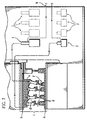
- plural groups of four upper electrode portions 6 such as a first group 31, a second group 32, a third group 33, a fourth group 34, a fifth group 35, etc. are arranged.
- one booster 16 is disposed as to correspond to four groups of the cylinder guns 13, and one check valve 15 and one branch valve 19 are disposed as to correspond to one group of the cylinder guns 13. That is to say, in Figure 4, one booster 16a corresponds to four groups, namely the first group 31 through the fourth group 34.
- the cooling water circulation duct 14 connected to the cooling water supplying device not shown in Figures, branches into plural first branch ducts 21 on an upstream portion, and the cooling water runs through each of the first branch ducts 21, each of the check valves 15, each group of the cylinder guns 13, and each of the branch valves 19 serially (refer to Figure 5). And, the cylinder guns 13 in one group are communicatively connected with the first branch duct 21 in series.
- a second branch duct 22 is disposed for connection to the booster 16 side, and a third branch duct 23 is disposed for avoiding the booster 16.
- four second branch ducts 22, corresponding to four branch valves 19, become confluent into one duct which reaches the cooling water supplying device (not shown in Figures) through one booster 16, and, four third branch ducts 23, corresponding to four branch valves 19, become confluent into one duct which reaches the cooling water supplying device (not shown in Figures). That is to say, the cooling water circulation duct 14 is composed of the first branch ducts 21, the second branch ducts 22, the third branch ducts 23, etc.
- air pipes 24, 25, 26, and 27 are provided as shown in Figure 4, the compressed air, supplied by a compressor not shown in Figures, is sent to each of the boosters 16, each of the branch valves 19, and each of the cylinder guns 13 through the air pipes 24, 25, 26, and 27.
- 28 represents an electropneumatic regulator
- 29 represents a booster valve for returning guns
- 30 represents a tank.
- FIG. 4 and Figure 5 show unpressurized state (non-welding state) of the cylinder guns 13 of each group, and each of the branch valves 19 is switched to close each of the second branch ducts 22. Therefore, the cooling water flowing in the cooling water circulating duct 14 is returned to the cooling water supplying device passing through each of the check valves 15, each of the cylinder guns 13, and each of the branch valves 19.
- the booster 16 (16a) is connected to the second branch duct 22 by switching the branch valve 19 (19a) corresponding to the first group 31.
- a piston valve portion 36 is moved by sending compressed air with switching the electromagnetic valve 20 corresponding to the branch valve 19a to close the branch duct 23 and open the branch duct 22.
- order of welding which does not necessarily start with the first group 31, can be freely set by controlling the electromagnetic valve 17 corresponding to the booster 16 and the electromagnetic valve 20 corresponding to the branch valve 19 of each group.
- the welding can be conducted with plural groups simultaneously, for example, the upper electrode portions 6 of the first group 31 and the upper electrode portions 6 of the fourth group 34 are simultaneously worked to weld.
- electrode pressurizing control of each welding point is possible by the booster 16, and the welding can be conducted with high accuracy.
- one booster 16 may be corresponding to one to three groups or more than five groups of the upper electrode portions 6. And, number of the upper electrode portions 6 for one group is freely determined. And, in case that number of groups corresponding to one booster 16 is small, for example, a case that one booster 16 corresponds to only one group of the upper electrode portions 6, the branch valve 19 may be omitted.
- the welding apparatus of the present invention simplification of construction and reduction of production cost can be obtained because conventionally necessary stop valves and electric circuit can be omitted. And, parts change and maintenance of the apparatus become easy, and change of the installation site becomes easy for use of the small check valves 15. And, it is possible to attach the apparatus directly to a die attachment port which is conventionally impossible to attach the apparatus to, length of piping of the cooling water circulation duct 14 can be shortened, and delay of pressurizing the cylinder gun caused by inflation of high-pressure hose of piping in pressurization is lessened and follow-up ability is improved thereby.
- the welding apparatus of the present invention in a welding apparatus having many upper electrode portions 6, number of the boosters 16 can be greatly reduced, for example, from conventional 18 units to 4 units, by corresponding one branch valve 19 and one check valve 15 to one group of the upper electrode portions 6, piping becomes easy and production cost can be reduced by reduction of assembly man hour and space. And, pressurization control for each welding point becomes possible for adopting the electropneumatic regulator for pressure control of the booster 16, multi-point welding with high accuracy and stable quality can be conducted thereby. That is to say, electrode pressurizing force control, welding element for stabilizing welding quality, can be established.
- pressure sensors which detect water pressure in the cylinder guns must be disposed to each duct of many boosters conventionally, number of the pressure sensors can be greatly reduced accompanying the reduction of the number of the boosters 16 in the present invention.
- construction of the elevation driving mechanism 8 becomes simple, and number of parts and production cost of the driving system can be reduced. And, material cost for the electrode die portion is reduced because change of die height (height of the die) is possible and the die height can be set low. Further, change of the die can be automatic and production operating rate is improved.
Landscapes
- Engineering & Computer Science (AREA)
- Mechanical Engineering (AREA)
- Resistance Welding (AREA)
Applications Claiming Priority (2)
| Application Number | Priority Date | Filing Date | Title |
|---|---|---|---|
| JP14579799A JP3335322B2 (ja) | 1999-05-26 | 1999-05-26 | 溶接装置 |
| JP14579799 | 1999-05-26 |
Publications (3)
| Publication Number | Publication Date |
|---|---|
| EP1057570A2 true EP1057570A2 (de) | 2000-12-06 |
| EP1057570A3 EP1057570A3 (de) | 2003-02-05 |
| EP1057570B1 EP1057570B1 (de) | 2006-04-26 |
Family
ID=15393384
Family Applications (1)
| Application Number | Title | Priority Date | Filing Date |
|---|---|---|---|
| EP99115099A Expired - Lifetime EP1057570B1 (de) | 1999-05-26 | 1999-08-09 | Schweissgerät |
Country Status (5)
| Country | Link |
|---|---|
| US (1) | US6373020B1 (de) |
| EP (1) | EP1057570B1 (de) |
| JP (1) | JP3335322B2 (de) |
| CA (1) | CA2282920C (de) |
| DE (1) | DE69931037T2 (de) |
Families Citing this family (5)
| Publication number | Priority date | Publication date | Assignee | Title |
|---|---|---|---|---|
| GB0801917D0 (en) * | 2008-02-01 | 2008-03-12 | Saipem Spa | Method and apparatus for the welding of pipes |
| US20140183167A1 (en) * | 2012-12-28 | 2014-07-03 | Hyundai Motor Company | Welding device for panel sheets and welding method for the same |
| KR101518914B1 (ko) * | 2013-09-30 | 2015-05-11 | 현대자동차 주식회사 | 스폿 용접장치 |
| KR101423201B1 (ko) | 2014-02-06 | 2014-07-24 | 한국훼스토 주식회사 | 스폿 용접건의 냉각수 순환장치 |
| CN119328383B (zh) * | 2024-12-20 | 2025-08-22 | 山东建业建设发展集团有限公司 | 一种建筑钢结构焊接施工用钢结构焊接对接设备 |
Family Cites Families (18)
| Publication number | Priority date | Publication date | Assignee | Title |
|---|---|---|---|---|
| US2057794A (en) * | 1934-04-27 | 1936-10-20 | Ford Motor Co | Welding machine |
| US2097377A (en) * | 1936-05-29 | 1937-10-26 | William H Martin | Welding machine |
| US2975264A (en) * | 1958-05-28 | 1961-03-14 | Fetz Alfred | Welding organization |
| US3927295A (en) * | 1974-02-01 | 1975-12-16 | Babcock & Wilcox Ltd | Welding system |
| ZA755040B (en) * | 1975-08-05 | 1976-08-25 | Gundle Plastics Pty Ltd | Improvements in or relating to the continuous or semi-continuous welding of sheet materials |
| US4439665A (en) * | 1982-04-26 | 1984-03-27 | Jetline Engineering, Inc. | Arc welding apparatus having pivotably mounted electrode carriage |
| US4439664A (en) * | 1982-04-26 | 1984-03-27 | Jetline Engineering, Inc. | Welding apparatus wherein physical contact of welding electrode with workpiece is mechanically sensed |
| AT374708B (de) * | 1982-10-22 | 1984-05-25 | Evg Entwicklung Verwert Ges | Vielpunkt-gitterschweissmaschine |
| JPS6156782A (ja) * | 1984-08-29 | 1986-03-22 | Takao Kinzoku Kogyo Kk | 溶接装置 |
| JPS61135488A (ja) * | 1984-12-06 | 1986-06-23 | Takao Kinzoku Kogyo Kk | 溶接装置 |
| JPH0438948Y2 (de) * | 1987-12-03 | 1992-09-11 | ||
| JPH0215884A (ja) * | 1988-06-30 | 1990-01-19 | Takao Kinzoku Kogyo Kk | 溶接装置 |
| US5121873A (en) * | 1990-06-06 | 1992-06-16 | Hitachi Ltd. | Method of and apparatus for joining hot materials to be rolled to each other as well as continuous hot rolling method and system |
| US5789719A (en) * | 1991-05-02 | 1998-08-04 | Milco Manufacturing Co. | Method and apparatus for electrical resistance spot welding |
| JP2506402Y2 (ja) * | 1991-10-11 | 1996-08-07 | 川崎重工業株式会社 | スポット溶接ロボット用制御装置 |
| JP3114440B2 (ja) * | 1993-07-22 | 2000-12-04 | 日産自動車株式会社 | スポット溶接装置 |
| DE69406614T2 (de) * | 1993-08-25 | 1998-06-25 | Toyota Motor Co Ltd | Steuerverfahren zum Punktschweissen, und Vorrichtung die eine gesteuerte Schweisszange benützt |
| JP3580330B2 (ja) * | 1995-10-03 | 2004-10-20 | 日産自動車株式会社 | 溶接装置の制御方法 |
-
1999
- 1999-05-26 JP JP14579799A patent/JP3335322B2/ja not_active Expired - Lifetime
- 1999-08-09 DE DE69931037T patent/DE69931037T2/de not_active Expired - Lifetime
- 1999-08-09 EP EP99115099A patent/EP1057570B1/de not_active Expired - Lifetime
- 1999-08-16 US US09/374,996 patent/US6373020B1/en not_active Expired - Lifetime
- 1999-09-21 CA CA002282920A patent/CA2282920C/en not_active Expired - Lifetime
Also Published As
| Publication number | Publication date |
|---|---|
| US6373020B1 (en) | 2002-04-16 |
| JP3335322B2 (ja) | 2002-10-15 |
| CA2282920A1 (en) | 2000-11-26 |
| DE69931037D1 (de) | 2006-06-01 |
| EP1057570A3 (de) | 2003-02-05 |
| CA2282920C (en) | 2005-08-16 |
| DE69931037T2 (de) | 2006-11-23 |
| JP2000334572A (ja) | 2000-12-05 |
| EP1057570B1 (de) | 2006-04-26 |
Similar Documents
| Publication | Publication Date | Title |
|---|---|---|
| CN101835601B (zh) | 用于弯曲压力机的驱动装置 | |
| US10982697B2 (en) | Hydraulic drive unit | |
| US6373020B1 (en) | Welding apparatus | |
| CN102641188A (zh) | 车辆用升降装置 | |
| US20150090132A1 (en) | Hydraulic extrusion press and method for operating a hydraulic extrusion press | |
| US4953458A (en) | Multi-actuator hydraulic press | |
| CN113819106B (zh) | 一种机械自动换向阀及其使用方法 | |
| KR100326648B1 (ko) | 업셋팅프레스의주구동장치 | |
| US1811138A (en) | Apparatus for pressure testing | |
| WO2015107567A1 (ja) | 液体供給装置 | |
| US20050084345A1 (en) | Dual motor tapping machine | |
| KR20190048727A (ko) | 단조 프레스용 제어 장치 | |
| WO2018028832A4 (de) | Hydraulische, insbesondere druckspeicherlose, antriebsanordnung für und mit einem verbraucher, insbesondere für pressen, sowie verfahren zum betreiben einer solchen hydraulischen antriebsanordnung | |
| US4439986A (en) | Hydraulic power unit | |
| DE19631804B4 (de) | Hydraulische Hubeinrichtung | |
| US4917580A (en) | Pump mechanism for simultaneous delivery of two atomizer liquids to a sprayer device | |
| CN115308014B (zh) | 一种静压脉冲试验台 | |
| CN221074801U (zh) | 一种伺服增压器 | |
| DE10214225C1 (de) | Verfahren zur Steuerung einer hydraulischen Betätigungseinheit | |
| CN210178668U (zh) | 液控自动补偿式增压装置 | |
| CN209818444U (zh) | 一种基于双向进压调节的液压缸位置控制系统 | |
| CN217063535U (zh) | 一种大推力持续推力工作状态的直线模组 | |
| CN223966624U (zh) | 自动调压夹钳检测装置 | |
| EP4353913A1 (de) | Steuer- und befehlsanordnung für einen hubarm einer arbeitsmaschine | |
| CN223289292U (zh) | 一种伺服压机的可切换式压头 |
Legal Events
| Date | Code | Title | Description |
|---|---|---|---|
| PUAI | Public reference made under article 153(3) epc to a published international application that has entered the european phase |
Free format text: ORIGINAL CODE: 0009012 |
|
| AK | Designated contracting states |
Kind code of ref document: A2 Designated state(s): AT BE CH CY DE DK ES FI FR GB GR IE IT LI LU MC NL PT SE |
|
| AX | Request for extension of the european patent |
Free format text: AL;LT;LV;MK;RO;SI |
|
| RIC1 | Information provided on ipc code assigned before grant |
Free format text: 7B 23K 11/36 A, 7B 23K 11/30 B, 7B 23K 11/31 B |
|
| PUAL | Search report despatched |
Free format text: ORIGINAL CODE: 0009013 |
|
| AK | Designated contracting states |
Designated state(s): AT BE CH CY DE DK ES FI FR GB GR IE IT LI LU MC NL PT SE |
|
| AX | Request for extension of the european patent |
Extension state: AL LT LV MK RO SI |
|
| 17P | Request for examination filed |
Effective date: 20030319 |
|
| AKX | Designation fees paid |
Designated state(s): DE ES FR GB IT SE |
|
| 17Q | First examination report despatched |
Effective date: 20050131 |
|
| GRAP | Despatch of communication of intention to grant a patent |
Free format text: ORIGINAL CODE: EPIDOSNIGR1 |
|
| RIN1 | Information on inventor provided before grant (corrected) |
Inventor name: MORISHITA,TAIICHIRO,C/OTAKAO KINZOKU KOGYO CO.LTD Inventor name: NAKAMURA, TADASHI,C/OTAKAO KINZOKU KOGYO CO. LTD. Inventor name: FUJITA, SHIGEO,C/O TAKAO KINZOKU KOGYO CO., LTD. |
|
| GRAS | Grant fee paid |
Free format text: ORIGINAL CODE: EPIDOSNIGR3 |
|
| GRAA | (expected) grant |
Free format text: ORIGINAL CODE: 0009210 |
|
| AK | Designated contracting states |
Kind code of ref document: B1 Designated state(s): DE ES FR GB IT SE |
|
| PG25 | Lapsed in a contracting state [announced via postgrant information from national office to epo] |
Ref country code: IT Free format text: LAPSE BECAUSE OF FAILURE TO SUBMIT A TRANSLATION OF THE DESCRIPTION OR TO PAY THE FEE WITHIN THE PRESCRIBED TIME-LIMIT;WARNING: LAPSES OF ITALIAN PATENTS WITH EFFECTIVE DATE BEFORE 2007 MAY HAVE OCCURRED AT ANY TIME BEFORE 2007. THE CORRECT EFFECTIVE DATE MAY BE DIFFERENT FROM THE ONE RECORDED. Effective date: 20060426 |
|
| REG | Reference to a national code |
Ref country code: GB Ref legal event code: FG4D |
|
| REF | Corresponds to: |
Ref document number: 69931037 Country of ref document: DE Date of ref document: 20060601 Kind code of ref document: P |
|
| PG25 | Lapsed in a contracting state [announced via postgrant information from national office to epo] |
Ref country code: SE Free format text: LAPSE BECAUSE OF FAILURE TO SUBMIT A TRANSLATION OF THE DESCRIPTION OR TO PAY THE FEE WITHIN THE PRESCRIBED TIME-LIMIT Effective date: 20060726 |
|
| PG25 | Lapsed in a contracting state [announced via postgrant information from national office to epo] |
Ref country code: ES Free format text: LAPSE BECAUSE OF FAILURE TO SUBMIT A TRANSLATION OF THE DESCRIPTION OR TO PAY THE FEE WITHIN THE PRESCRIBED TIME-LIMIT Effective date: 20060806 |
|
| ET | Fr: translation filed | ||
| PLBE | No opposition filed within time limit |
Free format text: ORIGINAL CODE: 0009261 |
|
| STAA | Information on the status of an ep patent application or granted ep patent |
Free format text: STATUS: NO OPPOSITION FILED WITHIN TIME LIMIT |
|
| 26N | No opposition filed |
Effective date: 20070129 |
|
| REG | Reference to a national code |
Ref country code: FR Ref legal event code: PLFP Year of fee payment: 18 |
|
| REG | Reference to a national code |
Ref country code: FR Ref legal event code: PLFP Year of fee payment: 19 |
|
| REG | Reference to a national code |
Ref country code: FR Ref legal event code: PLFP Year of fee payment: 20 |
|
| PGFP | Annual fee paid to national office [announced via postgrant information from national office to epo] |
Ref country code: FR Payment date: 20180820 Year of fee payment: 20 Ref country code: DE Payment date: 20180828 Year of fee payment: 20 |
|
| PGFP | Annual fee paid to national office [announced via postgrant information from national office to epo] |
Ref country code: GB Payment date: 20180720 Year of fee payment: 20 |
|
| REG | Reference to a national code |
Ref country code: DE Ref legal event code: R071 Ref document number: 69931037 Country of ref document: DE |
|
| REG | Reference to a national code |
Ref country code: GB Ref legal event code: PE20 Expiry date: 20190808 |
|
| PG25 | Lapsed in a contracting state [announced via postgrant information from national office to epo] |
Ref country code: GB Free format text: LAPSE BECAUSE OF EXPIRATION OF PROTECTION Effective date: 20190808 |