EP1057607A2 - Vorrichtung zur Entnahme eines gegossenen Produktes - Google Patents
Vorrichtung zur Entnahme eines gegossenen Produktes Download PDFInfo
- Publication number
- EP1057607A2 EP1057607A2 EP00111566A EP00111566A EP1057607A2 EP 1057607 A2 EP1057607 A2 EP 1057607A2 EP 00111566 A EP00111566 A EP 00111566A EP 00111566 A EP00111566 A EP 00111566A EP 1057607 A2 EP1057607 A2 EP 1057607A2
- Authority
- EP
- European Patent Office
- Prior art keywords
- mechanism unit
- time
- molded product
- retaining mechanism
- return
- Prior art date
- Legal status (The legal status is an assumption and is not a legal conclusion. Google has not performed a legal analysis and makes no representation as to the accuracy of the status listed.)
- Withdrawn
Links
Images


Classifications
-
- B—PERFORMING OPERATIONS; TRANSPORTING
- B29—WORKING OF PLASTICS; WORKING OF SUBSTANCES IN A PLASTIC STATE IN GENERAL
- B29C—SHAPING OR JOINING OF PLASTICS; SHAPING OF MATERIAL IN A PLASTIC STATE, NOT OTHERWISE PROVIDED FOR; AFTER-TREATMENT OF THE SHAPED PRODUCTS, e.g. REPAIRING
- B29C45/00—Injection moulding, i.e. forcing the required volume of moulding material through a nozzle into a closed mould; Apparatus therefor
- B29C45/17—Component parts, details or accessories; Auxiliary operations
- B29C45/40—Removing or ejecting moulded articles
- B29C45/42—Removing or ejecting moulded articles using means movable from outside the mould between mould parts, e.g. robots
-
- B—PERFORMING OPERATIONS; TRANSPORTING
- B29—WORKING OF PLASTICS; WORKING OF SUBSTANCES IN A PLASTIC STATE IN GENERAL
- B29C—SHAPING OR JOINING OF PLASTICS; SHAPING OF MATERIAL IN A PLASTIC STATE, NOT OTHERWISE PROVIDED FOR; AFTER-TREATMENT OF THE SHAPED PRODUCTS, e.g. REPAIRING
- B29C45/00—Injection moulding, i.e. forcing the required volume of moulding material through a nozzle into a closed mould; Apparatus therefor
- B29C45/17—Component parts, details or accessories; Auxiliary operations
- B29C45/76—Measuring, controlling or regulating
- B29C45/7626—Measuring, controlling or regulating the ejection or removal of moulded articles
-
- B—PERFORMING OPERATIONS; TRANSPORTING
- B22—CASTING; POWDER METALLURGY
- B22D—CASTING OF METALS; CASTING OF OTHER SUBSTANCES BY THE SAME PROCESSES OR DEVICES
- B22D17/00—Pressure die casting or injection die casting, i.e. casting in which the metal is forced into a mould under high pressure
- B22D17/20—Accessories: Details
- B22D17/22—Dies; Die plates; Die supports; Cooling equipment for dies; Accessories for loosening and ejecting castings from dies
- B22D17/2236—Equipment for loosening or ejecting castings from dies
-
- B—PERFORMING OPERATIONS; TRANSPORTING
- B29—WORKING OF PLASTICS; WORKING OF SUBSTANCES IN A PLASTIC STATE IN GENERAL
- B29C—SHAPING OR JOINING OF PLASTICS; SHAPING OF MATERIAL IN A PLASTIC STATE, NOT OTHERWISE PROVIDED FOR; AFTER-TREATMENT OF THE SHAPED PRODUCTS, e.g. REPAIRING
- B29C37/00—Component parts, details, accessories or auxiliary operations, not covered by group B29C33/00 or B29C35/00
- B29C37/0003—Discharging moulded articles from the mould
- B29C37/0007—Discharging moulded articles from the mould using means operable from outside the mould for moving between mould parts, e.g. robots
-
- B—PERFORMING OPERATIONS; TRANSPORTING
- B29—WORKING OF PLASTICS; WORKING OF SUBSTANCES IN A PLASTIC STATE IN GENERAL
- B29C—SHAPING OR JOINING OF PLASTICS; SHAPING OF MATERIAL IN A PLASTIC STATE, NOT OTHERWISE PROVIDED FOR; AFTER-TREATMENT OF THE SHAPED PRODUCTS, e.g. REPAIRING
- B29C45/00—Injection moulding, i.e. forcing the required volume of moulding material through a nozzle into a closed mould; Apparatus therefor
- B29C45/17—Component parts, details or accessories; Auxiliary operations
- B29C45/76—Measuring, controlling or regulating
- B29C45/7626—Measuring, controlling or regulating the ejection or removal of moulded articles
- B29C2045/7633—Take out or gripping means
-
- B—PERFORMING OPERATIONS; TRANSPORTING
- B29—WORKING OF PLASTICS; WORKING OF SUBSTANCES IN A PLASTIC STATE IN GENERAL
- B29C—SHAPING OR JOINING OF PLASTICS; SHAPING OF MATERIAL IN A PLASTIC STATE, NOT OTHERWISE PROVIDED FOR; AFTER-TREATMENT OF THE SHAPED PRODUCTS, e.g. REPAIRING
- B29C2945/00—Indexing scheme relating to injection moulding, i.e. forcing the required volume of moulding material through a nozzle into a closed mould
- B29C2945/76—Measuring, controlling or regulating
- B29C2945/76655—Location of control
- B29C2945/76719—Ejection unit
- B29C2945/76722—Ejection unit ejectors
-
- B—PERFORMING OPERATIONS; TRANSPORTING
- B29—WORKING OF PLASTICS; WORKING OF SUBSTANCES IN A PLASTIC STATE IN GENERAL
- B29C—SHAPING OR JOINING OF PLASTICS; SHAPING OF MATERIAL IN A PLASTIC STATE, NOT OTHERWISE PROVIDED FOR; AFTER-TREATMENT OF THE SHAPED PRODUCTS, e.g. REPAIRING
- B29C2945/00—Indexing scheme relating to injection moulding, i.e. forcing the required volume of moulding material through a nozzle into a closed mould
- B29C2945/76—Measuring, controlling or regulating
- B29C2945/76929—Controlling method
- B29C2945/76939—Using stored or historical data sets
-
- B—PERFORMING OPERATIONS; TRANSPORTING
- B29—WORKING OF PLASTICS; WORKING OF SUBSTANCES IN A PLASTIC STATE IN GENERAL
- B29C—SHAPING OR JOINING OF PLASTICS; SHAPING OF MATERIAL IN A PLASTIC STATE, NOT OTHERWISE PROVIDED FOR; AFTER-TREATMENT OF THE SHAPED PRODUCTS, e.g. REPAIRING
- B29C2945/00—Indexing scheme relating to injection moulding, i.e. forcing the required volume of moulding material through a nozzle into a closed mould
- B29C2945/76—Measuring, controlling or regulating
- B29C2945/76929—Controlling method
- B29C2945/76973—By counting
-
- Y—GENERAL TAGGING OF NEW TECHNOLOGICAL DEVELOPMENTS; GENERAL TAGGING OF CROSS-SECTIONAL TECHNOLOGIES SPANNING OVER SEVERAL SECTIONS OF THE IPC; TECHNICAL SUBJECTS COVERED BY FORMER USPC CROSS-REFERENCE ART COLLECTIONS [XRACs] AND DIGESTS
- Y10—TECHNICAL SUBJECTS COVERED BY FORMER USPC
- Y10T—TECHNICAL SUBJECTS COVERED BY FORMER US CLASSIFICATION
- Y10T29/00—Metal working
- Y10T29/49—Method of mechanical manufacture
- Y10T29/49002—Electrical device making
- Y10T29/49117—Conductor or circuit manufacturing
- Y10T29/49124—On flat or curved insulated base, e.g., printed circuit, etc.
- Y10T29/49155—Manufacturing circuit on or in base
- Y10T29/49158—Manufacturing circuit on or in base with molding of insulated base
- Y10T29/4916—Simultaneous circuit manufacturing
Definitions
- the present invention relates to an apparatus for taking out a molded product by letting the retaining mechanism unit for retaining a molded product penetrate between the die halves after die opening, for instance, in an injection molding machine.
- Take-out of a molded product is performed by a take-out apparatus for a molded product, which has a retaining mechanism unit for retaining a molded product and a moving mechanism unit for moving the retaining mechanism unit.
- the take-out operation of the take-out apparatus for a molded product is carried out in the way shown in FIGURE 6. Specifically, after die opening, the retaining mechanism unit which has been stopping at a waiting position (A) penetrates to an penetrating position (B) within the die halves. Then, the retaining mechanism unit moves toward a take-out position (C) and stops upon arrival at the take-out position (C) (1 ⁇ penetration process). At the take-out position (C), the retaining mechanism unit retains the molded product which has been separated from a die half (2 ⁇ take-out process). The retaining mechanism unit with the molded product retained moves back to a specified pulling out position (D) from the take-out position (C).
- the retaining mechanism unit After moving to a withdrawing position (E) (3 ⁇ withdrawal process), the retaining mechanism unit moves from the withdrawing position (E) to a retrieving position (F) where it liberates the molded product and when reaching the retrieving position (F), the retaining mechanism unit stops (4 ⁇ conveyance process). At the retrieving position (F), the molded product is released from holding by the retaining mechanism unit so that the molded product can be retrieved (5 ⁇ liberation process). Upon completion of liberating the molded product at the retrieving position (F), the retaining mechanism unit returns from the retrieving position (F) to the waiting position (A) (6 ⁇ return process) where the retaining mechanism unit waits until the next take-out operation for a molded product starts (7 ⁇ waiting process).
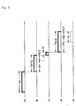
- a time chart for the above processes is constituted by the penetration/withdrawal time Tae (FIGURE 7(a)) which is required for the penetration process and the withdrawal process; the conveyance time Tef (FIGURE 7(b)) required for the conveyance process; the molded product liberation time Tf (FIGURE 7(c)) required for liberation at the retrieving position (F); the return time Tfa (FIGURE 7(d)) required for the return process and the wait time Ta (FIGURE 7(e)) required for waiting at the waiting position (A).
- the returning operation is set by the operator such that the retaining mechanism unit can move as fast as possible.
- a sufficient wait time is ensured for the retaining mechanism unit when waiting at the waiting position (A) in order that the retaining mechanism unit should penetrate between the die halves immediately after completion of the next die opening thereby executing the penetration process without fail.
- it is necessary to increase the moving speed of the retaining mechanism unit which involves rapid acceleration and rapid deceleration.
- the moving mechanism unit is therefore activated abruptly, entailing strong impact on the moving mechanism unit. As a result, there arise the problems of damage to the mechanical parts at an early stage and increased electric power consumption.
- a prime object of the invention is to reduce damage to the mechanical parts of a moving mechanism unit and electric power consumption in an apparatus for taking out a molded product, the apparatus comprising a retaining mechanism unit for retaining a molded product and a moving mechanism unit for moving the retaining mechanism unit, the apparatus being designed such that the retaining mechanism unit penetrates between die halves from a specified waiting position after die opening to take out the molded product and the molded product is liberated at a specified retrieving position which is located outside the die halves.
- an apparatus for taking out a molded product constructed according to the invention comprising:
- the retaining mechanism unit which has liberated the molded product at the retrieving position is moved from the retrieving position to the waiting position by carrying out returning operation with the moving mechanism unit, and the retaining mechanism unit temporarily stops and waits at the waiting position until completion of die opening.
- the return time taken for the returning operation and the wait time at the waiting position are measured by the time measuring means, and then, a return moving speed distribution which allows the returning operation to be carried out within the measured return time is calculated by the arithmetic means.
- the moving speed in the return moving speed distribution calculated herein includes the wait time for the preceding process so that the moving speed can be made slower than that of the conventional system in which await time is assured. In consequence, moderate acceleration and deceleration can be carried out in the invention.
- wait time substantially vanishes because the moving mechanism unit is activated based on an instruction from the controlling means according to the return moving speed distribution calculated by the arithmetic means, so that the activation of the moving mechanism unit at that time can be performed at a moderate speed.
- the invention is designed as described above and therefore exerts the following effects.
- the retaining mechanism unit is arranged such that its moving speed in returning operation is reduced thereby moderating acceleration and deceleration to slowly activate the moving mechanism unit, whereby damage to the mechanical parts of the moving mechanism unit and electric power consumption can be restricted. In consequence, the service life of the apparatus can be prolonged and the cost of electric power consumption can be reduced.
- the retaining mechanism unit takes the molded product out of the die halves and performs conveying operation in which the molded product is conveyed from a specified withdrawing position located outside the die halves to the retrieving position;
- FIGURE 1 is a block diagram showing the structure of an apparatus for taking out a molded product constructed according to the first embodiment of the invention.
- the molded product take-out apparatus of the first embodiment comprises a retaining mechanism unit 7 for taking a molded product out of die halves and a moving mechanism unit 5 for moving the retaining mechanism unit 7. It further comprises a time measuring unit 4, a position detecting unit 6 and a CPU (Central Processing Unit) 1.
- a CPU Central Processing Unit
- the retaining mechanism unit 7 is composed of a take-out arm and a take-out head attached to the distal end of the take-out arm.
- a take-out head By means of the take-out head, a molded product is retained by adsorption, chucking or clamping.
- the proximal end of the take-out arm is connected to the moving mechanism unit 5.
- the moving mechanism unit 5 includes a conveyance/return mechanism 51 and a penetration/withdrawal mechanism 52.
- the conveyance/return mechanism 51 allows the traversing movement of the retaining mechanism unit 7, thereby performing conveying operation (conveyance process) for conveyance from a withdrawing position (E) to a retrieving position (F) (see FIGURE 6) and returning operation (return process) for returning from the retrieving position (F) to a waiting position (A).
- the penetration/withdrawal mechanism 52 allows the ascending/descending movement of the retaining mechanism unit 7, thereby performing penetrating operation (penetration process) for penetration from the waiting position (A) to a take-out position (C) and withdrawing operation (withdrawal process) for withdrawal from the take-out position (C) to the withdrawing position (E).
- the position detecting unit 6 detects the movement position of the retaining mechanism unit 7 based on the driving amount of the moving mechanism unit 5, and it is determined whether the retaining mechanism unit 7 has reached each of the waiting position (A), the penetrating position (B), the take-out position (C), the pulling out position (D), the withdrawing position (E) and the retrieving position (F).
- the time measuring unit 4 measures the return time elapsing since a start of the return process in the preceding process (i.e., initializing operation) until a start of the penetration process which is carried out subsequently to a completion of the waiting process. This return time is measured by counting clock signals sent from the CPU 1.
- the CPU 1 controls the overall take-out apparatus based on a program prestored in a ROM 2.
- the CPU 1 performs signal processing to instruct activation of the moving mechanism unit 5, based on a signal from a die clamping mechanism unit 81 in a molding machine 8, a positional detection signal from the position detecting unit 6 and data stored in a RAM 3.
- the CPU 1 has an arithmetic operation unit 11 having a leaning function and the arithmetic operation unit 11 calculates a return moving speed distribution which allows the return process to be completed upon elapse of the return time measured by the time measuring unit 4.
- the CPU 1 contains a control unit 12 which activates the moving mechanism unit 5 such that the return process in the process succeeding the preceding process is performed according to the return moving speed distribution calculated by the arithmetic operation unit 11. Since the moving speed based on the return moving speed distribution calculated herein includes the wait time of the preceding process, it can be slower than the moving speed of the return process in the preceding process in which a wait time is assured, so that moderate acceleration and deceleration can be carried out.
- the basic operations (described earlier) of the present take-out apparatus are carried out in the following order: (1) penetration process (penetrating operation) ⁇ (2) take-out process (molded product retaining operation) ⁇ (3) withdrawal process (withdrawing operation ⁇ 4) conveyance process (conveying operation ⁇ (5) liberation process (liberating operation) ⁇ (6)return process (returning operation) ⁇ (7) waiting process.
- (1) penetration process, (3) withdrawal process, (4) conveyance process and (6) return process among the above processes the moving mechanism unit 5 is operated. The moving speed in each process is so set beforehand by the operator that each process can be finished in good time for starting the next molding cycle.
- the return process is carried out quickly in order to perform the penetration process in the next molding cycle without fail and assures sufficient wait time in the waiting process.
- the return process in the process succeeding the preceding process is performed by the learning function of the CPU 1 such that the above wait time can be vanished.
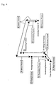
- the initializing operation for that is shown in the flow chart of FIGURE 2.
- the initializing operation i.e., the preceding process is performed as follows: First, at Step S1, the molded product is taken out of the die halves and the withdrawing operation is executed. Then, a check is made to determine whether the retaining mechanism unit 7 has reached the withdrawing position (E) outside the die halves, and if it is determined that the unit 7 has reached, the program proceeds to Step S2.
- a molding cycle start signal is outputted to the molding machine at Step S2 to execute the next molding cycle.
- the conveying operation in which the retaining mechanism unit 7 holding the molded product is moved from the withdrawing position (E) to the retrieving position (F) and the liberating operation in which the molded product is liberated at the retrieving position (F) are successively executed, and then the program proceeds to Step S3.
- the molding machine which has input a molding cycle start signal performs die clamping, injection of material and die opening successively as a molding cycle and issues a die opening limitation signal upon completion of die opening.
- Step 3 the liberating operation in which the molded product is released from the retaining mechanism unit 7 is carried out at the retrieving position (F) within the liberation time set by a timer function provided for the CPU 1; a check is made to determine whether the liberation time has elapsed; and if the liberation time has elapsed, the liberating operation is completed. Then, if it is determined that the liberating operation has been completed, the program proceeds to the next step S4.
- Step S4 time measurement is carried out by the time measuring unit 4 while the returning operation is performed to return the retaining mechanism unit 7 to the waiting position (A). Thereafter, the retaining mechanism unit 7 waits at the waiting position (A) until the moment when it inputs a die opening limitation signal which is indicative of a completion of die opening and sent from the die opening mechanism unit 81 of the molding machine 8.
- Step S5 it is determined whether the die opening limitation signal has been input and if it is determined that the die opening limitation signal has been input, the penetrating operation of the next molding cycle starts to execute take-out of a molded product and the program proceeds to Step S6.
- Step S6 the measurement by the time measuring unit 4 is stopped and the total time (i.e., return time) of the return time taken for the returning operation and the wait time in the wait process is measured.
- the arithmetic operation unit 11 of the CPU 1 calculates a return moving speed distribution which allows the returning operation to be terminated upon elapse of the return time which has been measured by the time measuring unit 4.
- the calculation of the return moving speed distribution is performed, for instance, according to the table shown in FIGURE 3.
- the speed distribution of the moving speed V1 of the returning operation which is set by the operator beforehand, is represented by a trapezoidal curve D1 constituted by an acceleration zone ascending diagonally to the right, an intermediate constant speed zone, and a deceleration zone descending diagonally to the right.
- the return time for the returning operation in this case is designated by Tfa.
- the wait time at the waiting position (A) is designated by Ta.
- a trapezoidal curve D2 is determined which allows the returning operation to be terminated upon elapse of the return time Tfa (1).
- the method for determining the trapezoidal curve D2 of this embodiment is as follows: The lower base is set to the return time Tfa (1), whereas the upper base is equalized to the preset time Tv of the intermediate constant speed zone having the moving speed V1. Then, the height V2 is determined such that the area of the region enclosed by the trapezoidal curve D2 becomes equal to the area of the region enclosed by the trapezoidal curve D1. The height V2 represents the return moving speed. Accordingly, by making the area of the region enclosed by the trapezoidal curve D2 equal to the area of the region enclosed by the trapezoidal curve D1, the moving distance based on the trapezoidal curve D2 can be equalized to the moving distance based on the trapezoidal curve D1. This means that if the returning operation is carried out at the return moving speed V2 according to the trapezoidal curve D2, it takes the return time Tfa (1) after a start of the returning operation until a completion of the returning operation.
- the return moving speed distribution based on the trapezoidal curve D2 is calculated during the time between a start of the penetrating operation in which take-out of the molded product is executed at Step S5 and a start of the returning operation which is performed subsequently to the liberation of the molded product at the retrieving position (F).
- Step S8 the conveyance/return mechanism 51 of the moving mechanism unit 5 is activated upon receipt of a command from the control unit 12 of the CPU 1, in such a way that the retaining mechanism unit 7, which has liberated the molded product at the retrieving position (F) and is about to start the returning operation, is moved according to the speed distribution of the return moving speed V2 which has been calculated at Step S7.
- This returning operation is carried out taking the return time Tfa (1) which has been calculated at Step S6. Therefore, the retaining mechanism unit 7 arrives at the waiting position (A) at the moment when the return time Tfa(1) has elapsed after the start of the returning operation.
- the succeeding process takes place later in such a way that the retaining mechanism unit 7 is moved according to the return moving speed distribution based on the trapezoidal curve D2 in the return process and moved at a preset moving speed in other processes which are the penetration process, withdrawal process and conveyance process.
- (1) penetration process, (2) take-out process, (3) withdrawal process, (4) conveyance process, (5) liberation process, (6) return process and (7) waiting process are carried out in order.
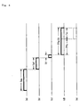
- the time chart for these processes comprises, as shown in FIGURE 4, the penetration/withdrawal time Tae (FIGURE 4(a)) required for the penetration process and the withdrawal process, the conveyance time Tef (FIGURE 4(b)) required for the conveyance process, the liberation process Tf (FIGURE 4(c)) required for the liberation of the molded product at the retrieving position (F) and the return time Tfa(1) (FIGURE 4(d)) required for the return process.
- the wait time Ta (FIGURE 4(e)) required for waiting at the waiting position (A) is substantially eliminated from this time chart, because it is merged into the prior return process. Specifically, the return process takes-the return time (Tfa(1)) and the retaining mechanism unit 7 therefore reaches the waiting position upon completion of die opening so that the retaining mechanism unit 7 only momentarily stops at the waiting position (A).
- the speed distribution of the return moving speed V2 is calculated so as to include the wait time Ta of the preceding process which firstly takes place and therefore, the return moving speed V2 can be made slower than the moving speed V1 of the returning operation in which the wait time Ta is assured (V1>V2).
- acceleration and deceleration can be carried out moderately (see FIGURE 3).
- the moving mechanism unit 5 is activated according to the speed distribution of the return moving speed V2 and therefore the wait time substantially vanishes, so that the activation of the moving mechanism unit 5 in this case can be carried out moderately.
- damage to the mechanical parts of the moving mechanism unit 5 and electric power consumption can be restricted. Accordingly, an apparatus capable of providing longer service life and lower electric consumption can be attained.
- the time measuring unit 4 further measures the conveyance time Tef in the conveyance process. This measurement starts at a start of the conveying operation in the preceding process (i.e., initializing operation).
- the arithmetic operation unit 11 of the CPU 1 calculates moving speed distributions for the conveyance process and for the return process which are carried out, taking the total time (Tef + Tfa(1)) of the conveyance time Tef and the return time Tfa(1) (see FIGURE 4).
- the control unit 12 of the CPU 1 actuates the conveyance/return mechanism 51 of the moving mechanism unit 5 such that the operations of the conveyance process and the return process are respectively carried out according to the above moving speed distributions.
- the time measuring unit 4 starts a time measurement upon input of a withdrawing position arrival signal which indicates that the retaining mechanism unit 7 has arrived at the withdrawing position (E) shown in FIGURE 6 and which is sent from the position detecting unit 6.
- the time measuring unit 4 terminates the time measurement upon input of a die opening limitation signal similarly to the case of the first embodiment 1.
- the liberation time Tf required for liberation at the retrieving position (F) is included in the time measured herein and the liberation time Tf is given beforehand because it is preset by the timer function of the CPU 1. Therefore, the total time (Tef + Tfa(1)) of the conveyance time Tef and the return time Tfa(a) can be calculated by subtracting the liberation time Tf from the above measured time.
- a specified time is allocated, according to the total time (Tef + Tfa(1)), to the conveyance time Tef(1) of the conveyance process and to the return time Tfa(2) of the return process.
- Ta/2 hours are allocated, as shown in the time chart of FIGURE 5, to the conveyance time Tef(1) and the return time Tfa(2) respectively, Ta being the wait time calculated in accordance with the conveyance speed and return speed which are preset by the operator in the preceding process.
- moving speed distributions in the form of trapezoidal curves such as shown in FIGURE 3 are respectively calculated for the conveyance process and for the return process, based on the conveyance time Tef(1) and the return time Tfa(2).
- the conveyance speed of the conveyance process and the return speed of the return process are slower than their corresponding moving speeds preset by the operator and therefore acceleration and deceleration in question become moderate.
- the conveyance/return mechanism 51 of the moving mechanism unit 5 is activated such that the operations in the conveyance process and the return process are carried out in accordance with the conveyance speed distribution and the return speed distribution calculated in the way described above.
- the second embodiment is arranged such that acceleration and deceleration can be carried out moderately not only in the returning operation of the return process but also in the conveying operation of the conveyance process so that damage to the mechanical parts of the moving mechanism unit 7 and electric power consumption can be still more restricted.
- an alternative arrangement may be employed in which the latter half of the return process is set as a wait area; the retaining mechanism unit 7 is moved at a speed slower than the return moving speed V2; the retaining mechanism unit 7 receives during its movement a command for starting the penetration process; and the retaining mechanism unit 7 does not stop at the waiting position (A).
- abrupt acceleration and abrupt deceleration can be accordingly restrained by making the retaining mechanism unit 7 wait while moving, so that damage to the mechanical part of the moving mechanism unit 7 and electric power consumption can be still more restricted similarly to the foregoing embodiments.
- trapezoidal curves such as shown in FIGURE 3 are used for the moving speed distributions in the foregoing embodiment, triangular curves, parabolic curves or the like which have no intermediate constant speed zone may be used.
- the so -called, side entry type may be adapted in which the penetration and withdrawal of the retaining mechanism unit 7 with respect to the die halves is carried out by the lateral movement of the retaining mechanism unit 7.
- the invention is applicable to all types of injection molding machines which require removal of a molded product after die opening and examples of which are injection molding machines for producing molded products from resin and injection molding machines for producing molded products from magnesium or aluminum.
- An object is to reduce damage to the mechanical parts of a moving mechanism unit 5 for moving a retaining mechanism unit 7 and electric power consumption in an apparatus for taking out a molded product.
- the apparatus comprises a time measuring unit 4 for measuring a return time elapsing between a start of the returning operation of the retaining mechanism unit 7 in a preceding process and the next start of the penetrating operation tor taking out a molded product; an arithmetic operation unit 11 for calculating a return moving speed distribution for a process succeeding the preceding process such that the returning operation terminates upon elapse of the return time measured by the time measuring means 4; and a control unit 12 for activating the moving mechanism unit 5 in such a way that the returning operation is carried out according to the return moving speed distribution in the succeeding process.
Landscapes
- Engineering & Computer Science (AREA)
- Mechanical Engineering (AREA)
- Manufacturing & Machinery (AREA)
- Robotics (AREA)
- Moulds For Moulding Plastics Or The Like (AREA)
- Injection Moulding Of Plastics Or The Like (AREA)
Applications Claiming Priority (2)
| Application Number | Priority Date | Filing Date | Title |
|---|---|---|---|
| JP11151995A JP3054868B1 (ja) | 1999-05-31 | 1999-05-31 | 成形品の取出装置 |
| JP15199599 | 1999-05-31 |
Publications (2)
| Publication Number | Publication Date |
|---|---|
| EP1057607A2 true EP1057607A2 (de) | 2000-12-06 |
| EP1057607A3 EP1057607A3 (de) | 2001-02-28 |
Family
ID=15530772
Family Applications (1)
| Application Number | Title | Priority Date | Filing Date |
|---|---|---|---|
| EP00111566A Withdrawn EP1057607A3 (de) | 1999-05-31 | 2000-05-30 | Vorrichtung zur Entnahme eines gegossenen Produktes |
Country Status (4)
| Country | Link |
|---|---|
| US (1) | US6532397B1 (de) |
| EP (1) | EP1057607A3 (de) |
| JP (1) | JP3054868B1 (de) |
| KR (1) | KR20000077124A (de) |
Cited By (3)
| Publication number | Priority date | Publication date | Assignee | Title |
|---|---|---|---|---|
| WO2004089595A1 (de) * | 2003-04-10 | 2004-10-21 | Hekuma Gmbh | Verfahren und vorrichtung zum steuern der bewegungsabläufe zwischen einer produktionsmaschine und einem handlingsystem |
| WO2011130761A1 (de) * | 2010-04-23 | 2011-10-27 | Wittmann Kunststoffgeräte Gmbh | VERFAHREN ZUR ENTNAHME VON SPRITZGIEßARTIKELN |
| DE102017124182B4 (de) | 2016-10-18 | 2019-09-19 | Engel Austria Gmbh | Regelvorrichtung für ein Handlinggerät |
Families Citing this family (2)
| Publication number | Priority date | Publication date | Assignee | Title |
|---|---|---|---|---|
| JP2007007989A (ja) * | 2005-06-30 | 2007-01-18 | Yushin Precision Equipment Co Ltd | 転写装置を備えた成形機 |
| US8509942B2 (en) * | 2011-03-31 | 2013-08-13 | Furukawa Electronic Co., Ltd. | Method for producing metal ingot, method for controlling liquid surface, and ultrafine copper alloy wire |
Family Cites Families (12)
| Publication number | Priority date | Publication date | Assignee | Title |
|---|---|---|---|---|
| JPS61114832A (ja) | 1984-11-09 | 1986-06-02 | Fanuc Ltd | 工程モニタができる射出成形機 |
| DE3744804C2 (de) | 1986-04-01 | 1990-12-06 | Toshiba Kikai K.K., Tokio/Tokyo, Jp | |
| JPH0649310B2 (ja) | 1987-03-31 | 1994-06-29 | 積水化学工業株式会社 | 射出成形装置における製品取出制御システム |
| DE4110948C3 (de) | 1991-04-05 | 1997-10-09 | Remak Maschinenbau Gmbh | Verfahren zur Entnahme von Spritzgießartikeln aus einer Spritzgießmaschine |
| DE59208251D1 (de) * | 1991-09-12 | 1997-04-24 | Engel Gmbh Maschbau | Verfahren zur steuerung einer maschine für die herstellung von produkten, insbesondere zur steuerung einer spritzgiessmaschine |
| JPH0664015A (ja) | 1992-08-12 | 1994-03-08 | Toshiba Mach Co Ltd | 実稼動中の射出成形機の成形条件変更方法 |
| DE59606596D1 (de) * | 1995-09-19 | 2001-04-19 | Siemens Ag | Automatisierungssystem für das steuern und regeln von maschinen und anlagen der kunststoffindustrie |
| US5786999A (en) * | 1995-10-04 | 1998-07-28 | Barber-Colman Company | Combination control for injection molding |
| US6000831A (en) * | 1997-02-12 | 1999-12-14 | American Msi Corporation | Injection mold data transmission system |
| EP0917034B1 (de) * | 1997-11-14 | 2002-03-06 | Engel Maschinenbau Gesellschaft Mbh | Verfahren zur Fernüberwachung und/oder Fernwartung einer Spritzgiessmaschine |
| US6128548A (en) * | 1998-05-08 | 2000-10-03 | Lear Corporation | Tool-specific control for carousel foam molding system |
| US6377863B1 (en) * | 1999-04-01 | 2002-04-23 | Universal Ventures | Computer-controlled operation of command-input device of automated-production machine |
-
1999
- 1999-05-31 JP JP11151995A patent/JP3054868B1/ja not_active Expired - Lifetime
-
2000
- 2000-05-02 KR KR1020000023421A patent/KR20000077124A/ko not_active Withdrawn
- 2000-05-25 US US09/577,480 patent/US6532397B1/en not_active Expired - Lifetime
- 2000-05-30 EP EP00111566A patent/EP1057607A3/de not_active Withdrawn
Cited By (7)
| Publication number | Priority date | Publication date | Assignee | Title |
|---|---|---|---|---|
| WO2004089595A1 (de) * | 2003-04-10 | 2004-10-21 | Hekuma Gmbh | Verfahren und vorrichtung zum steuern der bewegungsabläufe zwischen einer produktionsmaschine und einem handlingsystem |
| WO2011130761A1 (de) * | 2010-04-23 | 2011-10-27 | Wittmann Kunststoffgeräte Gmbh | VERFAHREN ZUR ENTNAHME VON SPRITZGIEßARTIKELN |
| CN102858515A (zh) * | 2010-04-23 | 2013-01-02 | 威特曼塑料仪器有限责任公司 | 用于取出注塑品的方法 |
| CN102858515B (zh) * | 2010-04-23 | 2016-02-24 | 威特曼塑料仪器有限责任公司 | 用于取出注塑品的方法 |
| US9387614B2 (en) | 2010-04-23 | 2016-07-12 | Wittmann Kunststoffgeraete Gmbh | Method for removing injection-molded items |
| DE102017124182B4 (de) | 2016-10-18 | 2019-09-19 | Engel Austria Gmbh | Regelvorrichtung für ein Handlinggerät |
| US10981316B2 (en) | 2016-10-18 | 2021-04-20 | Engel Austria Gmbh | Control device for a handling device |
Also Published As
| Publication number | Publication date |
|---|---|
| JP3054868B1 (ja) | 2000-06-19 |
| EP1057607A3 (de) | 2001-02-28 |
| JP2000334772A (ja) | 2000-12-05 |
| KR20000077124A (ko) | 2000-12-26 |
| US6532397B1 (en) | 2003-03-11 |
Similar Documents
| Publication | Publication Date | Title |
|---|---|---|
| JP3030555B1 (ja) | 成形品の取出装置 | |
| JP3881940B2 (ja) | 干渉回避制御装置 | |
| US5629031A (en) | Remover for injection-molded article | |
| JP2979404B1 (ja) | 射出成形品取出装置の制御方法及びこれを実施する射出成形品取出装置 | |
| US6532397B1 (en) | Apparatus for taking out molded products | |
| KR100241093B1 (ko) | 사출성형기의 형개폐속도 제어방법 | |
| JPH042417B2 (de) | ||
| EP1728616A1 (de) | Regeleinrichtung für eine Spritzgiessmachine | |
| KR100854820B1 (ko) | 다이캐스팅 머신에서의 제품 취출방법 및 그 장치 | |
| US9387614B2 (en) | Method for removing injection-molded items | |
| JP3487819B2 (ja) | 成形品の取出装置 | |
| JPH07125024A (ja) | 射出成形機の制御方法 | |
| JP2002059465A (ja) | 成形品の取出方法及びその装置 | |
| JP2007083489A (ja) | 成形品取出機 | |
| JPH11235738A (ja) | 樹脂成形品の取出装置を備えた射出成形機 | |
| JP6426523B2 (ja) | 射出成形システム | |
| JPS62170312A (ja) | 成形機における製品引出方法およびその機構 | |
| KR100481406B1 (ko) | 취출기의 동작시간 제어방법 | |
| JP3247405B2 (ja) | 押出成形機における成形品の取出し方法及び装置 | |
| JP2002178376A (ja) | 成型品取出機 | |
| JP2002172660A (ja) | 成型品取出機の取出し制御方法 | |
| JP2001145946A (ja) | 成形品の取出装置 | |
| JPH053814B2 (de) | ||
| JPH06293059A (ja) | パリソンピンチ方法 | |
| JP2026066781A (ja) | 搬送装置の制御装置 |
Legal Events
| Date | Code | Title | Description |
|---|---|---|---|
| PUAI | Public reference made under article 153(3) epc to a published international application that has entered the european phase |
Free format text: ORIGINAL CODE: 0009012 |
|
| AK | Designated contracting states |
Kind code of ref document: A2 Designated state(s): DE FR GB IT NL |
|
| AX | Request for extension of the european patent |
Free format text: AL;LT;LV;MK;RO;SI |
|
| PUAL | Search report despatched |
Free format text: ORIGINAL CODE: 0009013 |
|
| AK | Designated contracting states |
Kind code of ref document: A3 Designated state(s): AT BE CH CY DE DK ES FI FR GB GR IE IT LI LU MC NL PT SE |
|
| AX | Request for extension of the european patent |
Free format text: AL;LT;LV;MK;RO;SI |
|
| RIC1 | Information provided on ipc code assigned before grant |
Free format text: 7B 29C 33/44 A, 7B 29C 45/40 B, 7B 29C 45/76 B, 7B 29C 45/42 B, 7B 29C 37/00 B, 7B 25J 9/00 B |
|
| 17P | Request for examination filed |
Effective date: 20010508 |
|
| AKX | Designation fees paid |
Free format text: DE FR GB IT NL |
|
| STAA | Information on the status of an ep patent application or granted ep patent |
Free format text: STATUS: THE APPLICATION IS DEEMED TO BE WITHDRAWN |
|
| 18D | Application deemed to be withdrawn |
Effective date: 20021203 |