EP1058055A1 - Systeme de combustion catalytique - Google Patents
Systeme de combustion catalytique Download PDFInfo
- Publication number
- EP1058055A1 EP1058055A1 EP99959870A EP99959870A EP1058055A1 EP 1058055 A1 EP1058055 A1 EP 1058055A1 EP 99959870 A EP99959870 A EP 99959870A EP 99959870 A EP99959870 A EP 99959870A EP 1058055 A1 EP1058055 A1 EP 1058055A1
- Authority
- EP
- European Patent Office
- Prior art keywords
- combustion
- catalytic
- catalyst
- chamber
- catalytic combustion
- Prior art date
- Legal status (The legal status is an assumption and is not a legal conclusion. Google has not performed a legal analysis and makes no representation as to the accuracy of the status listed.)
- Granted
Links
Images












Classifications
-
- F—MECHANICAL ENGINEERING; LIGHTING; HEATING; WEAPONS; BLASTING
- F23—COMBUSTION APPARATUS; COMBUSTION PROCESSES
- F23C—METHODS OR APPARATUS FOR COMBUSTION USING FLUID FUEL OR SOLID FUEL SUSPENDED IN A CARRIER GAS OR AIR
- F23C13/00—Apparatus in which combustion takes place in the presence of catalytic material
-
- F—MECHANICAL ENGINEERING; LIGHTING; HEATING; WEAPONS; BLASTING
- F23—COMBUSTION APPARATUS; COMBUSTION PROCESSES
- F23C—METHODS OR APPARATUS FOR COMBUSTION USING FLUID FUEL OR SOLID FUEL SUSPENDED IN A CARRIER GAS OR AIR
- F23C13/00—Apparatus in which combustion takes place in the presence of catalytic material
- F23C13/02—Apparatus in which combustion takes place in the presence of catalytic material characterised by arrangements for starting the operation, e.g. for heating the catalytic material to operating temperature
-
- F—MECHANICAL ENGINEERING; LIGHTING; HEATING; WEAPONS; BLASTING
- F23—COMBUSTION APPARATUS; COMBUSTION PROCESSES
- F23D—BURNERS
- F23D14/00—Burners for combustion of a gas, e.g. of a gas stored under pressure as a liquid
- F23D14/28—Burners for combustion of a gas, e.g. of a gas stored under pressure as a liquid in association with a gaseous fuel source, e.g. acetylene generator, or a container for liquefied gas
-
- F—MECHANICAL ENGINEERING; LIGHTING; HEATING; WEAPONS; BLASTING
- F23—COMBUSTION APPARATUS; COMBUSTION PROCESSES
- F23C—METHODS OR APPARATUS FOR COMBUSTION USING FLUID FUEL OR SOLID FUEL SUSPENDED IN A CARRIER GAS OR AIR
- F23C2900/00—Special features of, or arrangements for combustion apparatus using fluid fuels or solid fuels suspended in air; Combustion processes therefor
- F23C2900/13001—Details of catalytic combustors
-
- F—MECHANICAL ENGINEERING; LIGHTING; HEATING; WEAPONS; BLASTING
- F23—COMBUSTION APPARATUS; COMBUSTION PROCESSES
- F23D—BURNERS
- F23D2900/00—Special features of, or arrangements for burners using fluid fuels or solid fuels suspended in a carrier gas
- F23D2900/00001—Special features of, or arrangements for burners using fluid fuels or solid fuels suspended in a carrier gas local catalytic coatings applied to burner surfaces
-
- F—MECHANICAL ENGINEERING; LIGHTING; HEATING; WEAPONS; BLASTING
- F23—COMBUSTION APPARATUS; COMBUSTION PROCESSES
- F23D—BURNERS
- F23D2900/00—Special features of, or arrangements for burners using fluid fuels or solid fuels suspended in a carrier gas
- F23D2900/14—Special features of gas burners
- F23D2900/14481—Burner nozzles incorporating flow adjusting means
-
- F—MECHANICAL ENGINEERING; LIGHTING; HEATING; WEAPONS; BLASTING
- F23—COMBUSTION APPARATUS; COMBUSTION PROCESSES
- F23N—REGULATING OR CONTROLLING COMBUSTION
- F23N2237/00—Controlling
- F23N2237/12—Controlling catalytic burners
Definitions
- the present invention relates to a catalytic combustion apparatus for combustion of gaseous fuel or liquid fuel.
- FIG. 29 Existing catalytic combustion apparatus is of a configuration as illustrated in Fig. 29, for example.
- numeral 1 is a gas tank for storing liquefied petroleum gas such as butane, propane, and the like. Fuel gas contained inside the gas tank 1 is ejected from a gas nozzle 3 passing through a gas passage 2. The gas ejected from the gas nozzle 3 draws in air through an air intake 4 by the effect of gas flow ejection and is mixed with air in a mixing chamber 5, and is then supplied to a combustion chamber 6. There being a catalytic body 7 inside the combustion chamber 6, the mixed gas burns by the catalytic action as it passes an internal passage 7' of the catalytic body 7 and generates combustion heat.
- An ignition device 8 is provided opposite the mixed gas entrance of the combustion chamber 6.
- the mixed gas is ignited by a spark generated by a spark plug 9 provided on the tip of the ignition device 8.
- the catalytic body 7 is heated by a flame formed downstream the catalytic body 7.
- catalytic combustion starts to take place on the surface of the catalytic body 7, the supply of the mixed gas to the flame is stopped, and the flame disappears.
- the mixed gas supplied to the combustion chamber 6 undergoes catalytic combustion over the entire catalytic body 7, and the combustion gas is exhausted from an exhaust port 10.
- Such a catalytic combustion apparatus is being applied in portable irons and warming devices.
- existing catalytic body 7 is generally a cylindrical honeycomb made of ceramic or metal supporting a catalyst. As its diameter is roughly determined by the amount of combustion, the height of the burner cannot be made smaller than this diameter. Furthermore, when the catalytic body 7 is made unreasonably small, it will present a problem of not being able to obtain a predetermined heating value as the combustion characteristic is lowered.
- the present inventors had already developed a thin type catalytic combustion system in which the height of the burner was made low by disposing a catalytic body formed in the shape of a flat plate with its planar area greater than the area of the side, and providing a gas passage on the catalytic body to allow flow of mixed gas in the lateral direction.
- a catalytic body formed in the shape of a flat plate with its planar area greater than the area of the side, and providing a gas passage on the catalytic body to allow flow of mixed gas in the lateral direction.
- difficulties were faced in the method of fabrication.
- the present invention addresses the above described issues of the prior arts. It is an object of the present invention to make a smaller and thinner burner by making the height and length smaller while securing ignitability thereby to provide a catalytic combustion apparatus which is superior in durability and portability.
- a first exemplary embodiment of the present invention comprises a combustor, a fuel tank, a valve, and an ignition device
- the combustor further comprises a gas nozzle, an air intake/ejector, a mixing chamber, a firing chamber, an ignition plug, a combustion chamber, a catalyst for combustion (first catalyst) housed in the combustion chamber, and an exhaust port
- the mixing chamber is a straight cylindrical passage
- a burner port is disposed on the boundary of the mixing chamber and the firing chamber, and the burner port comprises a catalytic net (second catalyst).
- a second exemplary embodiment is, in a catalytic combustion apparatus as described in the first exemplary embodiment, the combustion on the catalytic net is adjusted to half of the entire combustion thereby to quickly extinguish the flame to allow smooth transition to catalytic combustion as well as to halve the combustion on the catalytic net thus lengthening the life of both the catalytic net and the catalyst for combustion.
- a third exemplary embodiment of the present invention comprises a combustor, a fuel tank, a valve, and an ignition device, where the combustor further comprises a gas nozzle, an air intake/ejector, an air intake, a mixing chamber, a firing chamber, a burner port provided in the firing chamber, an ignition plug, a combustion chamber, a catalyst for combustion housed in the combustion chamber, and an exhaust port.
- An intake-air shutter is provided on the air intake which is operable by a temperature detecting means provided in the vicinity of the combustion chamber.
- the ratio of combustion on the catalytic net can be lowered by making the velocity of the fuel-air mixed gas passing through the catalytic net faster by increasing the air-to-fuel ratio after transition to catalytic combustion, thereby to secure life of the catalytic net. Also, by increasing the air-to-fuel ratio, the temperature of the catalyst for combustion is also lowered and the durability is improved.
- a fourth exemplary embodiment is a catalytic combustion apparatus as described in the first exemplary embodiment comprising a combustor, a fuel tank, a valve, and an ignition device, where the combustor further comprises a gas nozzle, an air intake/ejector, an air intake, a mixing chamber, a firing chamber, a burner port provided in the firing chamber, an ignition plug, a combustion chamber, a catalyst for combustion housed in the combustion chamber, and an exhaust port, and a quantity-of-flow adjustable means is provided between the valve and the combustor so that the adjustable range of the amount of combustion can be widened in a manner such that when the quantity of gas flow is reduced by adjusting the quantity-of-flow adjustable means, combustion will take place on the combustion net only, and when the quantity of gas flow is increased, combustion will take place on both the catalytic net and the catalyst for combustion.
- a fifth exemplary embodiment is an invention as described in the first exemplary embodiment comprising a combustor, a fuel tank, a valve, and an ignition device, in which the combustor further comprises a gas nozzle, an air intake/ejector, an air intake, a mixing chamber, a firing chamber, an ignition plug, a combustion chamber, a catalyst for combustion housed in the combustion chamber, and an exhaust port, and the mixing chamber is a straight cylindrical passage, a cylindrical firing chamber a side opening of which communicating with the combustion chamber is provided in parallel to the mixing chamber, a burner port is provided on the boundary between the mixing chamber and the firing chamber, the burner port is configured with a catalytic net, and the mixing chamber and a part of the catalytic net are made to come into contact with each other so that the heat of the catalytic net can be conducted to the combustor through the wall of the mixing chamber, thereby suppressing the temperature rise of the catalytic net and securing the life of the catalytic net.
- a sixth exemplary embodiment is one in which the catalytic net of the fifth exemplary embodiment is formed in the shape of a square-C letter so that its two sides come into contact with the wall of the mixing chamber thereby to remove dispersion of the area of contact between the mixing chamber and the catalytic net during assembly work and to obtain stable characteristic.
- a seventh exemplary embodiment is a catalytic combustion apparatus as described in the fifth exemplary embodiment, in which the catalytic net is formed in the shape of an open square so that its three sides come into contact with the wall of the mixing chamber. As it is made easy to maintain the shape of the catalytic net, dispersion of the area of contact between the mixing chamber and the catalytic net during assembly work can be removed, and stable characteristic can be obtained.
- An eighth exemplary embodiment is a catalytic combustion apparatus, in which the ignition plug is disposed in the end of the firing chamber where the density of combustion gas becomes high thereby to assure firing and allow reduction in size and thickness.
- a ninth exemplary embodiment is a catalytic combustion apparatus, in which a part of the catalyst for combustion is disposed in such a way that it projects into the firing chamber thereby to increase the speed of transition to catalytic combustion by increasing the rate of temperature rise of the catalyst for combustion and allow reduction in size and thickness.
- a tenth exemplary embodiment is a catalytic combustion apparatus, in which the air intake/ejector is provided with a quantity-of-flow adjustable means for varying the quantity of intake air thereby to improve combustion characteristic during catalytic combustion by increasing the ratio of excess air upon transition to catalytic combustion and allow reduction in size and thickness.
- An eleventh exemplary embodiment is a catalytic combustion apparatus, in which the valve comprises a solenoid valve and a control apparatus, and the control apparatus controls the solenoid valve in a manner such that the control apparatus temporarily closes the solenoid valve after an ignition device has operated and subsequently opens it again thereby to assure smooth transition to catalytic combustion and allow reduction in size and thickness.
- a twelfth exemplary embodiment is a catalytic combustion apparatus, in which the valve is provided with a quantity-of-flow adjustable means for adjusting the quantity of intake air, and the quantity-of-flow adjustable means is fully opened to allow the ignition device to ignite, and throttles back the quantity of supply of fuel gas after ignition thereby to assure stable ignition and transition to catalytic combustion and to allow reduction in size and thickness.
- a thirteenth exemplary embodiment is a catalytic combustion apparatus, in which the valve comprises a solenoid valve and a control apparatus, and the control apparatus controls the solenoid valve to be temporarily closed based on a signal from a temperature detecting means disposed in the combustion chamber thereby to assure ignition and stable transition to catalytic combustion and to allow reduction in size and thickness.
- a fourteenth exemplary embodiment is a catalytic combustion apparatus, in which the exhaust port is disposed on the combustor in such a manner that it will not overlap the combustion chamber and will come to a position opposite the direction of ejection of mixed gas into the mixing chamber thereby to allow uniform catalytic combustion through uniform passage of the mixed gas through the catalyst for combustion and reduction in size and thickness.
- a fifteenth exemplary embodiment is a catalytic combustion apparatus, in which a burner port area adjustable means provided on the combustor is operable with a signal from a temperature detecting means provided in the vicinity of the burner port thereby to allow instantaneous transition to catalytic combustion by reducing the open area of the burner port upon reaching catalytic combustion enabling temperature.
- a sixteenth exemplary embodiment is a catalytic combustion apparatus, in which the catalyst for combustion is affixed to the combustion chamber with a space between itself and the inner wall of the combustion chamber thereby to reduce the quantity of transfer of the heat generated by the catalyst for combustion to the combustor and to keep the temperature of the outer wall low even when the apparatus is downsized to obtain user-friendliness.
- a seventeenth exemplary embodiment is a catalytic combustion apparatus, in which the catalyst for combustion is provided with a thickness adjustable means for adjusting thickness thereby enabling adjustment of the quantity of heat transfer to the combustor in order to obtain a wide temperature control range.
- An eighteenth exemplary embodiment is a catalytic combustion apparatus, in which a catalytic body formed into the shape of a flat plate of which the area of the planer surface is greater than the area of the side is disposed inside the combustion chamber and a gas passage to allow flow of mixed gas in the lateral direction is provided on the catalytic body, thereby making the burner height low and providing a small size and thin catalytic combustion apparatus.
- a nineteenth exemplary embodiment is a catalytic combustion apparatus, in which a straight cylindrical gas passage communicating with the outlet of the mixing chamber is provided and the inlet of the combustion chamber is made to communicate with a side of the gas passage so that the mixing chamber and the catalytic body are disposed in parallel to each other thereby to shorten the burner length to obtain a compact design.
- a twentieth exemplary embodiment is a catalytic combustion apparatus, in which the length of the straight cylindrical gas passage is made longer than the width of the inlet of the combustion chamber and the inlet of the combustion chamber is disposed inside the straight cylindrical gas passage thereby to allow more uniform mixing of fuel gas and air and to uniformly supply the mixed gas to the catalytic body.
- a twenty-first exemplary embodiment is a catalytic combustion apparatus, in which a gas flow resistant body is provided in the outlet of the mixing chamber to reduce the velocity of mixed gas flow thereby to slow down the velocity of the mixed gas flow inside the straight cylindrical gas passage and to uniformly supply the mixed gas to the catalytic body.
- a twenty-second exemplary embodiment is a catalytic combustion apparatus, in which a gas rectifier is provided in the inlet of the combustion chamber to rectify the flow of mixed gas thereby to rectify the mixed gas that comes out from the straight cylindrical gas passage and to uniformly supply the mixed gas to the catalytic body.
- a twenty-third exemplary embodiment is a catalytic combustion apparatus, in which the catalytic body supports a catalyst on a corrugated carrier made by folding a thin metal sheet into the shape of continuous waves thereby to provide a catalytic body which is simple in shape, easy of continuous processing, and superior in mass producibility.
- a twenty-fourth exemplary embodiment is a catalytic combustion apparatus, in which the catalytic body supports a catalyst on a multilayer carrier fabricated by alternately stacking a corrugated sheet made by folding a thin metal sheet into the shape of continuous waves and a flat thin metal sheet thereby to secure high combustion efficiency even when the amount of combustion is increased.
- a twenty-fifth exemplary embodiment is a catalytic combustion apparatus comprising a nozzle for ejecting a fuel gas, a mixing chamber for making a mixed gas by mixing the fuel gas ejected from the nozzle and air, and a combustion chamber having a catalytic body inside it for burning the mixed gas, in which the combustion chamber is comprised of discrete components which can be divided into the mixing chamber, nozzle, and catalytic body, thereby to provide a small and thin catalytic combustion apparatus with a low burner height.
- a twenty-sixth exemplary embodiment is a catalytic combustion apparatus, in which the combustion chamber comprises a plurality of components divided by a plane approximately in parallel to the direction of ejection from the nozzle thereby to lower the height of the combustion chamber.
- a twenty-seventh exemplary embodiment is a catalytic combustion apparatus, in which a subassembly integrating the combustion chamber and the nozzle is secured by sandwiching with a plurality of components that comprise the combustion chamber thereby to downsize the mixing chamber and the nozzle.
- a twenty-eighth exemplary embodiment is a catalytic combustion apparatus, in which a temperature detecting means for detecting the temperature of the combustion chamber and a control unit for controlling the quantity of ejection of the fuel gas based on the output of the temperature detecting means are provided, and the temperature detecting means is secured by a plurality of components that comprise the combustion chamber thereby to simplify the structure of affixing the temperature detecting means to the combustion chamber, downsize the combustion chamber, as well as to assure securing of the temperature detecting means by sandwiching with the combustion chamber.
- Fig. 1 is a cross-sectional view to illustrate the overall structure of a catalytic combustion apparatus.
- Numeral 11 is a combustor
- numeral 12 is a fuel tank
- numeral 13 is a valve
- numeral 14 is an ignition device using a piezoelectric element
- numeral 16 is a gas nozzle
- numeral 17 is an ejector for drawing in air by the ejecting energy of fuel
- numeral 18 is a straight cylindrical mixing chamber for mixing a fuel gas and air
- numeral 19 is a cylindrical firing chamber of which an opening 24 on the side communicates with a combustion chamber 21.
- Numeral 20 is an ignition plug for generating a spark inside the firing chamber 19
- numeral 22 is a catalyst for combustion housed inside the combustion chamber 21
- numeral 23 is an exhaust port for discharging combustion gas.
- Numeral 25 is a burner port provided on the boundary between the mixing chamber 18 and the firing chamber 19 and is configured with a catalytic net 25a which supports a catalyst with platinum as the main component on a high heat resistance metal net.
- the catalytic net 25a supports approximately 2.5 mg of platinum which is capable of burning 70 to 80% of the fuel gas.
- a flame is formed on the catalytic net 25a where the catalyst for combustion 22 is heated to catalytic combustion enabling temperature.
- a flame is formed on the burner port 25 by opening the valve 13 to allow ejection of the fuel gas from the gas nozzle 16 and igniting it with the ignition device 14.
- the area of the opening of the burner port 25 is made small and the velocity of flow of the mixed gas is made high thereby forming a flame at some distance from the burner port 25.
- the flame approaches the catalyst for combustion 22, the catalyst for combustion 22 is easily heated, and the temperature of the catalyst for combustion 22 reaches 200 degrees C or higher in several seconds which is generally regarded as the catalytic combustion enabling temperature.
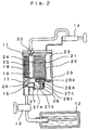
- Fig. 2 and Fig. 3 are cross-sectional views to illustrate the overall structure of a catalytic combustion apparatus.
- Numeral 26 is an air intake.
- Numeral 27 is an intake-air shutter comprising an L-shaped shutter 27a, an aperture for air intake 27b, and a tension spring 27c. The size of the aperture for air intake is designed to a size at which the quantity of air necessary for forming a flame at the burner port 25 without fail can be taken in.
- Numeral 28 is a temperature detecting means provided in the vicinity of the combustion chamber 21 and comprises a case 28a, a bimetal 28b, and an operating rod 28c. Other configuration is the same as in Fig. 1.
- the operating temperature of the temperature detecting means 28 is set at approximately 250 degrees C which is slightly higher than the catalytic combustion enabling temperature.
- the catalyst for combustion 22 is heated by a flame formed at the burner port 25, and the temperature of the catalyst for combustion 22 rises in several seconds to 200 degrees C or higher which is generally regarded as catalytic combustion enabling temperature.
- the heat capacity of the catalytic net 25a is small, its temperature instantly rises and catalytic combustion commences almost simultaneously on the catalytic net 25a, too, the flame formed on the burner port 25 spontaneously disappears, and catalytic combustion commences on the catalyst for combustion 22, too.
- the temperature detecting means 28 When the temperature of the catalyst for combustion 22 rises to 250 degrees C which is higher than the catalytic combustion enabling temperature, the temperature detecting means 28 operates to open the intake-air shutter 27, the area of the aperture is increased, and the quantity of the intake air is increased.
- the ratio of combustion on the catalytic net 25a is reduced by making the velocity of flow of mixed gas of the fuel gas and air faster, thereby lengthening the life of the catalytic net 25a.
- the temperature of the catalyst for combustion 22 is also reduced thus enhancing the durability.
- Fig. 4 is a cross-sectional view to illustrate a combustor of the catalytic combustion apparatus.
- Numeral 29 is a quantity-of-flow adjustable means such as a needle valve provided between a valve 13 and a combustor 11.
- Other structure is the same as the catalytic combustion apparatus in Fig. 1.
- the quantity of flow of the fuel gas is reduced by controlling the quantity-of-flow adjustable means 29, as the generated heat is insufficient, catalytic combustion cannot be maintained on such a catalyst with a large heat capacity as the catalyst for combustion 22.
- the heat capacity of the catalytic net 25a is small, catalytic combustion can be maintained even with a small amount of heat generation. Consequently, the adjustable range of the amount of combustion is widened by burning on the catalytic net 25a only when the flow rate is low, and burning on both the catalytic net 25a and the catalyst for combustion 22 when the flow rate of the fuel gas is increased.
- Fig. 5 is a cross-sectional view of an essential part of the combustion chamber of the catalytic combustion apparatus.
- a mixing chamber 18 and a part of a catalytic net 25a are in contact with each other thereby to transfer heat of the catalytic net 25a to the combustor 11 through the wall of the mixing chamber 18, control the temperature rise of the catalytic net 25a, and lengthen the life of the catalytic net 25a.
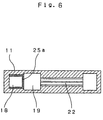
- Fig. 6 is a cross-sectional view of an essential part of a combustion chamber of another example of a catalytic combustion apparatus.
- Numeral 11 is a straight cylindrical passage having a rectangular cross-section and
- numeral 25a is a catalytic net formed to the shape of a square C-letter.
- the above described catalytic net 25a is formed to the shape of a square C-letter so that it comes into contact with the mixing chamber 18 on two sides. This way, the dispersion of the area of contact between the mixing chamber 18 and the catalytic net 25a during assembly work can be eliminated and stable characteristic can be obtained.
- Fig. 7 is a cross-sectional view of an essential part of a combustion chamber of still another example of a catalytic combustion apparatus.
- Numeral 11 is a straight cylindrical passage having a rectangular cross section and
- numeral 25a is a catalytic net formed to the shape of a square.
- the catalytic net 25a is formed to the shape of a square so that it comes into contact with the mixing chamber 18 on three sides. This way, by making it easy to maintain the shape of the catalytic net 25a, the dispersion of the area of contact between the mixing chamber 18 and the catalytic net 25a during assembly work can be eliminated and further stabilized characteristic can be obtained.
- Fig. 9 is a cross-sectional view to illustrate the structure of a part of the catalytic combustion apparatus shown in Fig. 1 to Fig. 4.
- a catalytic net 25a is housed inside a mixing chamber 18.
- the catalytic net 25a is disposed on the upper part of the burner port 25 described in the first example.
- the heat capacity of the catalytic net 25a is small and the temperature rises to a predetermined temperature in a short period of time, it has an extremely high flame-keeping effect. Consequently, a flame once formed by ignition of a mixed gas will not disappear due to the flame-keeping effect of the above-mentioned catalytic net 25a.
- a flame can be formed on the catalytic net 25a without fail, transition to catalytic combustion can be effected without fail even when the combustion chamber 21 is configured thin, thereby realizing a downsized and thin catalytic combustion apparatus.
- Fig. 10 is a cross-sectional view of an essential part of a catalytic combustion apparatus of this example.
- a portion 22a of a catalyst for combustion 22 is disposed in a manner such that it projects into a firing chamber 19.
- the catalyst for combustion 22 is housed inside the combustion chamber 21.
- the combustion chamber 21 is of dense structure, the heat capacity is large and it takes time for the catalyst for combustion 22 to reach a predetermined temperature.
- the portion 22a of the catalyst for combustion 22 is disposed in a manner such that it projects into the firing chamber 19 as described above.
- Most of the firing chamber 19 is an empty space with an extremely small heat capacity compared with that of the combustion chamber 21. Accordingly, in this example, the time during which the catalyst for combustion 22 reaches a predetermined temperature is made shorter by disposing a portion 22a of the catalyst for combustion 22 inside the firing chamber 19 with a small heat capacity.
- the speed of transition to catalytic combustion can be made faster by making the rate of temperature rise of the catalyst for combustion 22 higher thereby realizing a downsized and thin catalytic combustion apparatus.
- Fig. 11 is a cross-sectional view of a combustor 11 of a catalytic combustion apparatus in this example.
- a quantity-of-flow adjustable means 29 is provided on an air intake 30.
- the quantity-of-flow adjustable means comprises an opening/closing lid 29a and an opening/closing spring 29b.
- an opening 29c which is smaller than the open area of the air intake 30 is provided.
- the size of the opening 29c is designed in a manner such that an optimum quantity of air for ignition can be taken in.
- the opening/closing lid 29a overcomes the pressure of the opening/closing spring 29b and covers the surface of the air intake 30.
- the air to be taken in by an air intake/ejector 17 goes through the opening 29c which is provided on the opening/closing lid 29a.
- the air intake/ejector 17 takes in a small quantity of air thereby to supply a mixed gas with a low excess air ratio to a mixing chamber 18.
- the mixed gas with low excess air is easily fired meaning that firing can be done without fail.
- the opening/closing lid 29a is detached from the surface of the air intake 30 by the pushing force of the opening/closing spring 29b. That is, the air to be taken in by the air intake/ejector 17 during catalytic combustion goes through the air intake 30. Consequently, during catalytic combustion, the air intake/ejector 17 supplies to the mixing chamber 18 a mixed gas with a high excess air ratio by taking in a large amount of air.
- the amount of air in the mixed gas can be set at an optimum excess air ratio for each of firing and catalytic combustion thereby providing a downsized and thin catalytic combustion apparatus having a superior combustion characteristic of catalytic combustion.
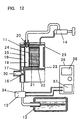
- Fig. 12 is a cross-sectional view to illustrate the overall structure of a catalytic combustion apparatus of this example.
- the valve as described in each of the above-described examples comprises a solenoid valve 34 and a control apparatus 35.
- the control apparatus 35 further comprises a timer circuit 36 and a relay circuit 37.
- the apparatus is controlled in a manner such that the solenoid valve 34 is temporarily closed by the timer circuit 36 and the relay circuit 37 for a certain period of time after an ignition device 14 has operated, and is reopened after a predetermined period of time has elapsed.
- Adoption of the above configuration enables extinction of a flame without fail after a catalyst for combustion 22 has been heated and stable transition to catalytic combustion.
- Fig. 13 is a cross-sectional view to illustrate the overall structure of a catalytic combustion apparatus of this example.
- a quantity-of-flow adjustable means 38 is provided on a valve 13.
- the quantity-of-flow adjustable means 38 has a cock 38a. In this example, by manually opening and closing the cock 38a, the quantity of fuel gas to be supplied from a fuel tank 12 can be adjusted.
- the cock 38a is fully opened when igniting so as to make the quantity of the fuel gas to be supplied from the fuel tank 12 to the maximum thereby lowering the excess air ratio and making ignition easy.
- the quantity of the fuel gas to be supplied from the fuel tank 12 is reduced by closing the cock 38a thereby increasing the excess air ratio. As a result, the flame spontaneously disappears and transition to catalytic combustion is quickly effected.
- a downsized and thin catalytic combustion apparatus is realized in which the valve 13 has a quantity-of-flow adjustable means 38, and ignition is made by operating the ignition device 14 while fully opening the quantity-of-flow adjustable means. Subsequently, by operating the quantity-of-flow adjustable means to control the quantity of supply of the fuel gas, stable transition to catalytic combustion is effected without fail.
- Fig. 14 is a cross-sectional view to illustrate the overall structure of a catalytic combustion apparatus of this example.
- a temperature detecting means 40 is provided in a combustion chamber 21.
- a thermistor is used as the temperature detecting means 40 in this example.
- Detected temperature information from the temperature detecting means 40 is transmitted to a control apparatus 39.
- the control apparatus 39 has a relay circuit 37 and a temperature detecting circuit 41.
- the control apparatus 39 Upon detecting that the temperature of a catalyst for combustion 22 has reached catalytic combustion enabling temperature based on the detected temperature information from the temperature detecting means 40, the control apparatus 39 controls a solenoid valve 34 so it is temporarily closed. As a result, the fuel gas supplied from a fuel tank 12 is suspended at the time the temperature of the catalyst for combustion 22 has reached the catalytic combustion enabling temperature. Accordingly, the flame burning in a firing chamber 19 is automatically extinguished thereby assuring transition to catalytic combustion.
- a downsized and thin catalytic combustion apparatus is realized in which ignition and transition to catalytic combustion are performed with stability and certainty.
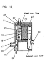
- FIG. 15 is a cross-sectional view of a combustor of a catalytic combustion apparatus of this example.
- an exhaust port 23 is provided on the combustor 11 at a position not overlapping a combustion chamber 21 and displaced in a direction opposite the direction of ejection of a mixed gas to a mixing chamber 19.
- the exhaust gas produced by catalytic combustion and to be exhausted from the exhaust port 23 will reach the exhaust port 23 while making contact with the combustion chamber 21.
- the amount of heat of the exhaust gas is absorbed by the combustion chamber 21, or is used to increase the temperature of the combustion chamber 21, the temperature of the exhaust gas is reduced.
- that portion of the mixed gas which is powerful is made far from the exhaust port 23 and that portion of the mixed gas which is weak is made near to the exhaust port 23 thereby allowing the mixed gas to uniformly pass through a catalyst for combustion 22.
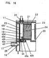
- Fig. 16 is a cross-sectional view to illustrate the structure of a combustor of this example.
- a combustor 11 has a burner port area adjustable means 42 for adjusting the area of a burner port 25.
- the burner port area adjustable means 42 is operable with a signal from a temperature detecting means 43 provided in the vicinity of the burner port 25.
- the burner port area adjustable means 42 comprises an L-shaped adjustable plate 42 and a tension spring 42b. On the adjustable plate 42 are provided the same number and size of adjustable holes 42c as that of the burner port 25.
- the temperature detecting means 43 comprises a case 43a, a bimetal 43b and an operating rod 43c.
- a heat sensing rod 43d is secured to the case 43a for better exposure to the heat of a flame formed on the burner port 25.
- the adjustable plate 42a is positioned in such a way that the positions of the adjustable hole 42c and the burner port 25 agree when there is no flame.
- the area of the aperture of the burner port 25 is reduced.
- the flame formed on the burner port 25 disappears. Consequently, the catalyst for combustion 22 can easily shift to catalytic combustion.
- the temperature of the heat sensitive rod 43d decreases, the bimetal 43d flips back again, and the adjustable plate 42a returns to its original position by the restoring force of the tension spring 42b.
- the catalyst for combustion 22 can instantaneously start catalytic combustion.
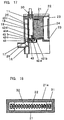
- Fig. 18 is a cross-sectional view to illustrate the structure of a combustor of this example.
- a catalyst for combustion 22 is affixed in a combustion chamber 21 with a space 32 between itself and the inner wall of the combustion chamber 21. To be more specific, it is affixed between a pair of square C-shaped spacers 31 provided on the inner wall 21a of the combustion chamber 21.
- the amount of heat generated by the catalyst for combustion 22 is kept inside the combustion chamber 21. That is, as the heat is retained by the layer of air existing in the space 32, the heat of catalytic combustion is made difficult to be conducted to the inner wall 21a. As a result, the temperature of the outer wall of the combustion chamber 21 is controlled to a low level even when the apparatus is downsized thereby providing an easy-to-use catalytic combustion apparatus.
- Fig. 19 and Fig. 20 are cross-sectional views to illustrate the configurations of a combustion chamber of this example.
- a catalyst for combustion 22 is provided with a thickness adjustable means 33.
- the thickness adjustable means 33 is composed of a pillar-shaped adjustable rod 33a having an oval cross-section.
- the catalyst for combustion 22 comprises two catalysts, namely, a first catalyst 22b and a second catalyst 22c disposed in a manner such that the adjustable rod 33a is sandwiched between them.
- the major axis of the adjustable rod 33a is in the horizontal direction, the thickness of the catalyst for combustion 22 becomes thin as illustrated in Fig. 19, whereas, when in the vertical direction, the thickness becomes thick as illustrated in Fig. 20. In this way, the thickness of the catalyst for combustion 22 can be freely varied by rotating the adjustable rod 33a.
- the quantity of heat generated by the catalyst for combustion 22 and conducted to a combustor 11 can be adjusted by adjusting the space 32 between the inner wall 21a of a combustion chamber 21 and the catalyst for combustion 22 thereby providing a catalytic combustion apparatus with a wide temperature control range.
- Fig. 21 is a cross-sectional view to illustrate a catalytic combustion apparatus of this example.
- Numeral 51 is a gas tank for storing liquefied petroleum gas such as butane and propane.
- a fuel gas inside the gas tank 51 is ejected from a gas nozzle 53 via a gas passage 52.
- a valve (not shown) for adjusting quantity of gas flow is provided between the gas tank 51 and the gas nozzle 53.
- the fuel gas ejected from the gas nozzle 53 draws in air from an air intake 54 by the ejection effect of the gas flow and is mixed with air in a mixing chamber 55.
- the exit of the mixing chamber 55 communicates with a straight cylindrical gas passage 56.
- a side of the straight cylindrical gas passage 56 communicates with a combustion chamber 58 which has a catalytic body 57.
- the combustion chamber 58 is disposed inside the straight cylindrical gas passage 56.
- an end portion of the combustion chamber 58 is positioned at a distance D inward from an end portion of a straight cylindrical gas passage 56.
- the catalytic body 57 is of a configuration as illustrated in Fig. 22.
- Fig. 22 is a perspective view to illustrate the shape of a catalytic body used in this exemplary example.
- a continuously corrugated thin sheet of metal consisting of stainless steel and the like is used as the carrier of the catalyst.
- a platinum group metal or an oxide of metals such as nickel, cobalt, iron, manganese, or chromium is used as the catalyst.
- a platinum group metal such as platinum, palladium, or rhodium. As illustrated in Fig.
- the catalytic body 57 is formed in the shape of a flat plate in a manner such that the planer area as represented by width A x length B is greater than the side area as represented by width A x thickness B.
- this catalyst carrier can be easily formed by processing a 0.05 to 0.1 mm thick stainless steel foil, for example.
- the catalyst carrier is one which is easy of continuous processing and is superior in mass producibility.
- the catalyst carrier is of a continuous corrugated configuration, a large surface area per unit volume is obtainable. That is, improvement in catalytic performance can be expected.
- Fig. 23 is a cross-sectional view of a section housing the above described catalytic body 57.
- the corrugated portion "a" functions as a gas passage.
- the combustion gas flows sideways passing this gas passage (hereafter called gas passage "a"). Also, the combustion gas undergoes catalytic combustion while it passes the gas passage "a”.
- an ignition device 59 is provided on the side opposite to the entrance of the combustion chamber 58.
- the ignition device 59 is operated to generate a spark on a plug 60 on the tip.
- a flame is formed downstream the catalytic body 57 by the spark, and the catalytic body 57 is heated by the flame.
- catalytic combustion begins on the surface of the catalytic body 57 and the flame disappears.
- the mixed gas supplied to the combustion chamber 58 undergoes catalytic reaction over the entire surface of the catalytic body 57 and generates heat as it passes the gas passage "a" of the catalytic body 57, and the combustion gas after reaction is exhausted from an exhaust port 61.
- the amount of combustion of a catalytic combustion apparatus is determined by the area (cross-sectional area) of the entrance of the catalytic body for the mixed gas if the catalytic material and the surface area of the entire catalytic body are the same. Consequently, when simply only the thickness of the catalytic body is reduced, the area of entrance is also reduced thus making it unable to obtain equivalent combustion characteristic and resulting in a poor combustion rate. For this reason, in this example, entrance area is secured by increasing the width A to compensate for the reduction in the thickness T of the catalytic body 57. As a result, according to the present example, the thickness can be reduced without reducing the combustion characteristic. Furthermore, as the catalytic body 57 is configured by continuous processing of a thin metal sheet as described before thereby to provide a large surface area per unit volume, further downsizing is enabled when compared with the prior art.
- the ejection velocity of the fuel gas ejected from the nozzle 53 is on the order of several 100 m/sec and the velocity of flow of the mixed gas flowing out from the mixing chamber 55 is also very high.
- a diffuser is provided at the exit of the mixing chamber 55 to gradually widen the area of the passage thereby making the flow velocity uniform.
- a longer diffuser is needed as the width of the entrance of the combustion chamber 58 increases, thereby resulting in a catalytic combustion apparatus having longer length and larger width.
- a communicating straight cylindrical gas passage 56 is provided at the exit of the mixing chamber 55 as has been described, and an entrance to the combustion chamber 58 is formed on a side of the straight cylindrical gas passage 56 so as to communicate with the entrance.
- the positional relation between the mixing chamber 55 and the catalytic body 57 is not serial but parallel.
- the mixed gas from the mixing chamber 55 first linearly flows inside the straight cylindrical gas passage 56.
- a reverse flow is caused inside the straight cylindrical gas passage 56 due to impingement.
- This reverse flow and the mixed gas supplied by the mixing chamber 55 interfere with each other.
- the flow velocity inside the straight cylindrical gas passage 56 becomes drastically small, static pressure of the entire inside of the straight cylindrical gas passage 56 increases, and the mixed gas flows to the direction of the combustion chamber 58 that communicates with the side of the straight cylindrical gas passage 56.
- the length of the straight cylindrical gas passage 56 is designed to be longer than the width of the entrance of the combustion chamber 57 and the entrance portion of the combustion chamber 58 is disposed within the length of the straight cylindrical gas passage 56.
- the position of the end portion of the combustion chamber 58 is recessed by a distance D from the end portion 56a of the straight cylindrical gas passage 56. Consequently, the reverse flow gas arising from the impingement at the front end portion 56a of the straight cylindrical passage 56 is prevented from directly entering into the combustion chamber 58, and the mixed gas uniformly mixed with air can be uniformly supplied into the combustion chamber 58.
- the mixed gas to be supplied to the combustion chamber 58 will become one in which the fuel gas and air are more uniformly mixed during the time the static pressure rises. Also, the distribution of flow velocity of the mixed gas at the entrance of the combustion chamber 58 will become uniform thereby enabling uniform supply of the mixed gas to the catalytic body 57.
- the catalytic combustion apparatus of the present example provides combustion heat of 60 watts or higher when the size is 6 mm in thickness and 50 mm in length. Consequently, when it is used in a warming cloth to be worn for warming the body, for example, there will be no feeling of wrongness and a product with superior portability may be realized.
- an apparatus with combustion heat on the order of 10 watts can be rightfully configured smaller and thinner than the above-mentioned dimension thus enabling use in small warmers such as gloves, shoes, or socks, for warming fingers of the hands or feet, or in thermotherapy curing device for treatment by applying the hot spot to arbitrary effective points.
- a gas resistant body 62 made of metal mesh or expanded metal and the like is provided at the exit of the mixing chamber 55 as illustrated in Fig. 21.
- the gas resistant body 62 reduces the flow velocity of the mixed gas coming out from the mixing chamber 55 thereby reducing the flow velocity inside the straight cylindrical gas passage 56.
- the distribution of flow velocity of the mixed gas at the entrance of the combustion chamber 58 can be made further uniform.
- the diameter of the straight cylindrical gas passage 56 can be made smaller thereby enabling reduction of the overall size of the combustion apparatus.
- a gas rectifier 63 made of metal mesh or expanded metal and the like is provided at the entrance of the combustion chamber 58.
- the gas rectifier 63 acts in a manner such that a mixed gas flowing from the straight cylindrical gas passage 56 to the combustion chamber 58 is rectified. Even when a vortex of mixed gas flow is produced inside the straight cylindrical gas passage 56 due to reasons such as fluctuation in the quantity of flow of the fuel gas, stable supply of mixed gas to the entire catalytic body 57 is enabled.
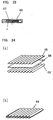
- Fig. 24(a) is an exploded perspective view of a catalytic body 64 employed in a catalytic combustion apparatus of the present example.
- Fig. 24(b) is an assembled perspective view of the catalytic body 64.
- the catalytic body 64 is comprised of corrugated sheets 65 and 65' made by continuously folding thin metal sheet of stainless steel and the like and a flat plate 66 of thin metal sheet.
- the corrugated sheets 65 and 65' are made of 0.05 mm thick thin metal sheet and the flat plate 66 is made of 0.1 mm thick thin metal sheet.
- a catalyst carrier is configured by stacking by spot welding, for example, one or more of these into a multilayer structure.
- the catalyst supported by this catalyst carrier is the same as described in the first example. Similar to the description in the first example, the catalytic body 64 is of flat plate configuration in which the planer area is greater than the cross-sectional area. Also, when housed in a combustion chamber 58, the waved portion forms a gas passage along which a mixed gas flows in the lateral direction.
- the surface area per unit volume can be made greater than the configuration described in the first example. As a result, when the size of the catalytic body is the same, larger amount of combustion can be obtained.
- the flat plate 66 will not come into contact with the inner wall of the combustion chamber 58. Consequently, when adjusting the temperature of the flat plate 66 which has risen higher than the temperature of the corrugated sheets 65 and 65' by turning on and off the fuel gas, it is easy to maintain active temperature of the catalyst. That is, dying of combustion is made difficult to take place.
- the temperature difference between upstream and downstream of the mixed gas undergoing catalytic combustion on the catalytic body 64 is made smaller by the heat unifying action of the flat plate 66. Accordingly, the present example is advantageous to the life of the catalytic body 64, too.
- the corrugated sheets 65 and 65' were configured with 0.05 mm thick thin metal sheets and the flat plate 66 with a 0.1 mm thick thin metal sheet, the thickness is not restricted to these values.
- Fig. 25 is a perspective view to illustrate configuration of a catalytic body 67 employed in a catalytic combustion apparatus of the present invention.
- a corrugated sheet 68 made by folding thin metal sheet in the form of continuous waves
- a corrugated sheet 70 made similarly
- a corrugated sheet 72 made similarly
- a flat plate 69 made of thin metal sheet
- a flat plate 71 made similarly.
- a multilayer metal catalyst is made by joining these materials by spot welding, for example.
- an amount of combustion approximately 1.5 times that of the configuration described in the twelfth example is obtained.
- the entrance area for a mixed gas and the surface area of the catalyst can be enlarged by increasing the number of stacked layers, and catalytic bodies with different amount of combustion can be fabricated by increasing or decreasing only the number of components for configuring the catalytic body. Consequently, standardization of components is made easy thus enabling low cost manufacturing.
- Fig. 26 is a cross-sectional view to illustrate the configuration of a catalytic combustion apparatus of the present example.
- Numeral 81 is a gas tank for storing liquefied petroleum gas such as butane or propane.
- the fuel gas inside the gas tank 81 is ejected from an ejection outlet 83a of a nozzle 83 via a gas passage 82.
- a control valve 84 for adjusting gas flow rate is provided between the gas tank 81 and the nozzle 83.
- the fuel gas ejected from the ejection outlet 83a draws in air through an air intake 85 and is mixed with air in a mixing chamber 86.
- the exit of the mixing chamber 86 communicates with a roughly cylindrical gas passage 87.
- a side of the cylindrical gas passage 87 communicates with a combustion chamber 90 having a catalytic body 89 via a firing chamber 88 which is disposed adjacent to the side of the gas passage 87.
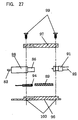
- the catalytic body 89 has a honeycomb cross-section as illustrated by a side view of Fig. 27, for example, and supports as a catalyst a platinum group metal or oxide of such metals as nickel, iron, manganese, or chromium on a carrier formed by corrugating thin metal sheets of stainless steel and the like.
- the fuel gas mixed with air undergoes catalytic combustion by catalytic action while it passes inside the catalytic body 89 after passing through the gas passage 87 and the firing chamber 88.
- an ignition device 91 is provided on the upper part of the firing chamber 88.
- a spark high voltage electric discharge spark
- a plug 91a on the tip by operating the ignition device 91.
- a flame is formed inside the firing chamber 88, and the catalytic body 89 is heated by the flame.
- Numeral 92 is a high tension wire to supply electricity to the ignition device 91.
- Numeral 94 is a temperature detecting means for detecting the temperature of the combustion chamber 90 and comprises a thermistor, thermocouple and the like, and is connected to a control unit 95.
- the control unit 95 is designed in a manner such that it controls the quantity of ejection of the fuel gas by driving a control valve 84 depending on the output from the temperature detecting means 94 and adjusts the temperature of the combustion chamber 90.
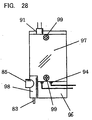
- the combustion chamber 90, the firing chamber 88, and the gas passage 87, etc. comprise two components divided by a plane parallel to the direction of flow of the mixed gas, namely, a lower base 96 and an upper base 97.
- Numeral 98 is a nozzle unit that integrates the air intake 85, the mixing chamber 86, and the nozzle 83 and is made by inserting the nozzle 83 into a cast component. It is also possible to configure it as an integral unit entirely by cutting work. In this example, as illustrated in Figs.
- the nozzle unit 98, catalytic body 89, ignition device 91, and temperature detecting means 94 are sandwiched between the two components, namely, the lower base 96 and the upper base 97, at a predetermined position, and secured by screwing a fixing screw 99 into a screw hole 100 provided on the lower base 96.
- the shape of the lower base 96 and the upper base 97 can be simplified thereby making processing easy, allowing reduction of the material thickness to a minimum thus enabling downsizing and thinner design.
- the nozzle unit 98 itself which requires a high degree of precision processing is made easier to process, suggesting the possibility of further downsizing by configuring an integral unit by cutting process of everything as described before.
- the combustion chamber 90 is divided into the lower base 96 and the upper base 97 by a plane roughly in parallel to the direction of ejection of the nozzle, the configuration for processing of the combustion chamber 90 section is greatly simplified thereby making processing easy, allowing reduction of the material thickness to a minimum thus achieving a low profile.
- combustion chamber 90 section is divided into upper and lower units, housing of the catalytic body 89 during assembly is made easy. Also, the assembling of the nozzle unit 98, the ignition device 91, and the temperature detecting means 94 is likewise easily done. Especially, as the temperature detecting means 94 has to detect the temperature of the combustion chamber 90 through heat conduction, although it is a general practice to fix it by pressing with a separate component made of a good heat conductor to ensure temperature detection, structure for fixing can be simplified by securing with the lower base 96 and the upper base 97 while sandwiching as in this configuration and temperature detection with higher reliability is assured.
- a catalytic combustion apparatus of the present invention comprises a combustor, a fuel tank, a valve, and an ignition device, and the combustor further comprises a gas nozzle, an air intake/ejector, a mixing chamber, a firing chamber, an ignition plug, a combustion chamber, a catalyst for combustion housed in the combustion chamber, and an exhaust port.
- the mixing chamber is made into a straight cylindrical passage, a cylindrical firing chamber is provided in parallel to the mixing chamber an opening on the side of the firing chamber communicating with the combustion chamber, a burner port is disposed on the boundary between the mixing chamber and the firing chamber, and the burner port comprises a catalyst net.
- the catalyst for combustion can start catalytic combustion by forming a flame on the upstream of the catalyst for combustion and heating the catalyst for combustion to catalytic combustion enabling temperature with the heat of the flame thereby causing catalytic combustion on the catalytic net, too, whereupon the flame spontaneously goes out allowing the combustion catalyst to commence catalytic combustion and suggesting that catalytic combustion can be effected without fail even when the combustion chamber configured with a low profile.
- the temperature rise of the catalyst for combustion is kept small and its life is elongated.
- the thickness of the catalytic body can be made smaller without sacrificing the igniting characteristic and durability, thereby enabling reduction in the burner height and providing a smaller and thinner catalytic combustion apparatus.
Landscapes
- Engineering & Computer Science (AREA)
- Chemical & Material Sciences (AREA)
- Combustion & Propulsion (AREA)
- Mechanical Engineering (AREA)
- General Engineering & Computer Science (AREA)
- Chemical Kinetics & Catalysis (AREA)
- Gas Burners (AREA)
- Spray-Type Burners (AREA)
Applications Claiming Priority (9)
| Application Number | Priority Date | Filing Date | Title |
|---|---|---|---|
| JP36100898 | 1998-12-18 | ||
| JP36100898A JP3937621B2 (ja) | 1998-12-18 | 1998-12-18 | 触媒燃焼装置 |
| JP10363262A JP2000186804A (ja) | 1998-12-21 | 1998-12-21 | 触媒燃焼装置 |
| JP36326298 | 1998-12-21 | ||
| JP08330999A JP3858508B2 (ja) | 1999-03-26 | 1999-03-26 | 触媒燃焼装置 |
| JP8330999 | 1999-03-26 | ||
| JP16488199A JP3855537B2 (ja) | 1999-06-11 | 1999-06-11 | 触媒燃焼装置 |
| JP16488199 | 1999-06-11 | ||
| PCT/JP1999/007090 WO2000037854A1 (fr) | 1998-12-18 | 1999-12-17 | Systeme de combustion catalytique |
Publications (3)
| Publication Number | Publication Date |
|---|---|
| EP1058055A1 true EP1058055A1 (fr) | 2000-12-06 |
| EP1058055A4 EP1058055A4 (fr) | 2005-05-18 |
| EP1058055B1 EP1058055B1 (fr) | 2009-10-14 |
Family
ID=27466812
Family Applications (1)
| Application Number | Title | Priority Date | Filing Date |
|---|---|---|---|
| EP99959870A Expired - Lifetime EP1058055B1 (fr) | 1998-12-18 | 1999-12-17 | Systeme de combustion catalytique |
Country Status (5)
| Country | Link |
|---|---|
| US (1) | US6394789B1 (fr) |
| EP (1) | EP1058055B1 (fr) |
| CN (1) | CN100368728C (fr) |
| DE (1) | DE69941535D1 (fr) |
| WO (1) | WO2000037854A1 (fr) |
Cited By (3)
| Publication number | Priority date | Publication date | Assignee | Title |
|---|---|---|---|---|
| WO2001063174A1 (fr) * | 2000-02-24 | 2001-08-30 | Swep International Ab | Dispositif pour le traitement catalytique de fluides |
| WO2005047769A3 (fr) * | 2003-11-14 | 2005-08-04 | Oglesby & Butler Res & Dev Ltd | A dispositif convertissant un gaz combustible en chaleur et dispositif chauffant a gaz |
| CN111503649A (zh) * | 2020-04-28 | 2020-08-07 | 聊城集众环保科技有限公司 | 一种吸附浓缩型蓄热式催化燃烧装置 |
Families Citing this family (14)
| Publication number | Priority date | Publication date | Assignee | Title |
|---|---|---|---|---|
| DE19901145A1 (de) * | 1999-01-14 | 2000-07-20 | Krieger Gmbh & Co Kg | Als Flächenstrahler ausgebildeter Infrarot-Strahler |
| KR100662168B1 (ko) * | 1999-08-19 | 2006-12-27 | 마츠시타 덴끼 산교 가부시키가이샤 | 촉매연소장치 및 연료기화장치 |
| US20040081871A1 (en) * | 2002-10-28 | 2004-04-29 | Kearl Daniel A. | Fuel cell using a catalytic combustor to exchange heat |
| JP2005055098A (ja) * | 2003-08-06 | 2005-03-03 | Denso Corp | 触媒反応ヒータ |
| KR100820233B1 (ko) * | 2006-10-31 | 2008-04-08 | 한국전력공사 | 연소기 및 이를 포함하는 멀티 연소기, 그리고 연소방법 |
| SE539758C2 (en) * | 2014-12-04 | 2017-11-21 | Powercell Sweden Ab | Catalytic burner arragement |
| CN106642646A (zh) * | 2015-10-29 | 2017-05-10 | 青岛经济技术开发区海尔热水器有限公司 | 燃气热水器及其控制方法 |
| CN108151012B (zh) * | 2016-12-04 | 2019-07-26 | 中国科学院大连化学物理研究所 | 一种甲醇气化和催化燃烧装置及操作方法 |
| CN108019740A (zh) * | 2017-11-20 | 2018-05-11 | 徐州工程学院 | 一种生物质燃料锅炉装置及其工作方法 |
| CN111397219B (zh) * | 2018-01-18 | 2021-07-27 | 芜湖美的厨卫电器制造有限公司 | 用燃气进行燃烧的机器的控制设备和方法及燃气热水器 |
| CN108343949B (zh) * | 2018-03-21 | 2019-11-01 | 山东京博石油化工有限公司 | 一种催化辅助燃烧室的燃烧方法 |
| CN111322611A (zh) * | 2018-12-13 | 2020-06-23 | 偿丰企业有限公司 | 热能模块 |
| CN110180387A (zh) * | 2019-07-02 | 2019-08-30 | 苏州仕净环保科技股份有限公司 | 一种污染气源的高效处理系统 |
| CN115468186B (zh) * | 2022-08-31 | 2024-03-22 | 常德市三一机械有限公司 | 燃烧器点火设备、点火方法及沥青站 |
Family Cites Families (16)
| Publication number | Priority date | Publication date | Assignee | Title |
|---|---|---|---|---|
| JPS5864412A (ja) * | 1981-10-13 | 1983-04-16 | Matsushita Electric Ind Co Ltd | 触媒燃焼装置 |
| JPS5864413A (ja) * | 1981-10-13 | 1983-04-16 | Matsushita Electric Ind Co Ltd | 触媒燃焼装置 |
| US5346389A (en) * | 1989-02-24 | 1994-09-13 | W. R. Grace & Co.-Conn. | Combustion apparatus for high-temperature environment |
| JP2724658B2 (ja) * | 1992-11-13 | 1998-03-09 | 松下電器産業株式会社 | 発熱装置 |
| US5403184A (en) * | 1992-05-20 | 1995-04-04 | Matsushita Electric Industrial Co., Ltd. | Exothermic apparatus |
| JP2797840B2 (ja) * | 1992-06-09 | 1998-09-17 | 松下電器産業株式会社 | 触媒燃焼装置 |
| JP3221972B2 (ja) * | 1993-04-22 | 2001-10-22 | 松下電器産業株式会社 | 触媒とそれを用いた触媒燃焼装置 |
| DE69528513T2 (de) * | 1994-12-06 | 2003-02-13 | Matsushita Electric Industrial Co., Ltd. | Verbrennungsgerät |
| US5928427A (en) * | 1994-12-16 | 1999-07-27 | Hwang; Chul-Ju | Apparatus for low pressure chemical vapor deposition |
| CN2207204Y (zh) * | 1994-12-30 | 1995-09-13 | 李勇 | 燃气催化型阻火防爆器 |
| IT1282428B1 (it) * | 1995-08-01 | 1998-03-23 | Zeltron Spa | Sistema di controllo per bruciatore catalitico |
| JPH09170708A (ja) * | 1995-12-19 | 1997-06-30 | Matsushita Electric Ind Co Ltd | 触媒燃焼装置 |
| SE9602688L (sv) * | 1996-07-08 | 1998-01-09 | Volvo Ab | Katalytisk brännkammare, samt förfarande för tändning och reglering av den katalytiska brännkammaren |
| JPH1089616A (ja) * | 1996-09-20 | 1998-04-10 | Matsushita Electric Ind Co Ltd | 触媒燃焼装置 |
| JPH10204706A (ja) * | 1997-01-09 | 1998-08-04 | Matsushita Electric Ind Co Ltd | 暖房衣服 |
| JP3281287B2 (ja) * | 1997-05-13 | 2002-05-13 | 田中貴金属工業株式会社 | 燃焼触媒体及びこれを用いたファンヒータ |
-
1999
- 1999-12-17 DE DE69941535T patent/DE69941535D1/de not_active Expired - Lifetime
- 1999-12-17 WO PCT/JP1999/007090 patent/WO2000037854A1/fr not_active Ceased
- 1999-12-17 CN CNB998029564A patent/CN100368728C/zh not_active Expired - Fee Related
- 1999-12-17 EP EP99959870A patent/EP1058055B1/fr not_active Expired - Lifetime
- 1999-12-17 US US09/622,129 patent/US6394789B1/en not_active Expired - Fee Related
Cited By (3)
| Publication number | Priority date | Publication date | Assignee | Title |
|---|---|---|---|---|
| WO2001063174A1 (fr) * | 2000-02-24 | 2001-08-30 | Swep International Ab | Dispositif pour le traitement catalytique de fluides |
| WO2005047769A3 (fr) * | 2003-11-14 | 2005-08-04 | Oglesby & Butler Res & Dev Ltd | A dispositif convertissant un gaz combustible en chaleur et dispositif chauffant a gaz |
| CN111503649A (zh) * | 2020-04-28 | 2020-08-07 | 聊城集众环保科技有限公司 | 一种吸附浓缩型蓄热式催化燃烧装置 |
Also Published As
| Publication number | Publication date |
|---|---|
| EP1058055B1 (fr) | 2009-10-14 |
| US6394789B1 (en) | 2002-05-28 |
| WO2000037854A1 (fr) | 2000-06-29 |
| CN1291273A (zh) | 2001-04-11 |
| EP1058055A4 (fr) | 2005-05-18 |
| DE69941535D1 (de) | 2009-11-26 |
| CN100368728C (zh) | 2008-02-13 |
Similar Documents
| Publication | Publication Date | Title |
|---|---|---|
| EP1058055B1 (fr) | Systeme de combustion catalytique | |
| EP2837884B1 (fr) | Brûleur | |
| US5403184A (en) | Exothermic apparatus | |
| US4455822A (en) | Device to ignite fuel injected in a rapidly flowing gaseous medium | |
| JP3858508B2 (ja) | 触媒燃焼装置 | |
| JP3855537B2 (ja) | 触媒燃焼装置 | |
| JP2572055B2 (ja) | 触媒燃焼装置 | |
| JP3793815B2 (ja) | ガス燃焼装置 | |
| JP2724658B2 (ja) | 発熱装置 | |
| JP3858481B2 (ja) | 触媒燃焼器 | |
| JP2932795B2 (ja) | 発熱装置 | |
| JP3098132B2 (ja) | 発熱装置 | |
| JPS58129106A (ja) | 燃焼装置 | |
| JP2002106810A (ja) | 触媒燃焼器 | |
| RU2156401C2 (ru) | Камера пульсирующего горения для подогрева воды | |
| JP3611381B2 (ja) | 燃焼器の制御装置および制御方法 | |
| JPS586352A (ja) | 温風暖房装置 | |
| JPH07324703A (ja) | 触媒燃焼装置 | |
| JP2000186804A (ja) | 触媒燃焼装置 | |
| JP2812062B2 (ja) | 発熱装置 | |
| JP2001235115A (ja) | 燃焼装置 | |
| JPS6238602B2 (fr) | ||
| JPH0151728B2 (fr) | ||
| JPS62280510A (ja) | ガス燃焼装置 | |
| JP2001201009A (ja) | 触媒燃焼装置 |
Legal Events
| Date | Code | Title | Description |
|---|---|---|---|
| PUAI | Public reference made under article 153(3) epc to a published international application that has entered the european phase |
Free format text: ORIGINAL CODE: 0009012 |
|
| 17P | Request for examination filed |
Effective date: 20000906 |
|
| AK | Designated contracting states |
Kind code of ref document: A1 Designated state(s): AT BE CH CY DE DK ES FI FR GB GR IE IT LI LU MC NL PT SE |
|
| RBV | Designated contracting states (corrected) |
Designated state(s): DE FR IT NL |
|
| A4 | Supplementary search report drawn up and despatched |
Effective date: 20050405 |
|
| RIC1 | Information provided on ipc code assigned before grant |
Ipc: 7F 23C 11/00 B Ipc: 7F 23D 14/28 B Ipc: 7F 23D 14/18 A |
|
| 17Q | First examination report despatched |
Effective date: 20060904 |
|
| RAP1 | Party data changed (applicant data changed or rights of an application transferred) |
Owner name: PANASONIC CORPORATION |
|
| GRAP | Despatch of communication of intention to grant a patent |
Free format text: ORIGINAL CODE: EPIDOSNIGR1 |
|
| RIC1 | Information provided on ipc code assigned before grant |
Ipc: F23C 13/06 20060101ALI20090407BHEP Ipc: F23D 14/28 20060101ALI20090407BHEP Ipc: F23D 14/18 20060101AFI20090407BHEP |
|
| RTI1 | Title (correction) |
Free format text: CATALYTIC COMBUSTION DEVICE |
|
| GRAS | Grant fee paid |
Free format text: ORIGINAL CODE: EPIDOSNIGR3 |
|
| GRAA | (expected) grant |
Free format text: ORIGINAL CODE: 0009210 |
|
| AK | Designated contracting states |
Kind code of ref document: B1 Designated state(s): DE FR IT NL |
|
| REF | Corresponds to: |
Ref document number: 69941535 Country of ref document: DE Date of ref document: 20091126 Kind code of ref document: P |
|
| PGFP | Annual fee paid to national office [announced via postgrant information from national office to epo] |
Ref country code: NL Payment date: 20091224 Year of fee payment: 11 |
|
| PGFP | Annual fee paid to national office [announced via postgrant information from national office to epo] |
Ref country code: IT Payment date: 20091217 Year of fee payment: 11 Ref country code: FR Payment date: 20100106 Year of fee payment: 11 |
|
| PLBE | No opposition filed within time limit |
Free format text: ORIGINAL CODE: 0009261 |
|
| STAA | Information on the status of an ep patent application or granted ep patent |
Free format text: STATUS: NO OPPOSITION FILED WITHIN TIME LIMIT |
|
| 26N | No opposition filed |
Effective date: 20100715 |
|
| PGFP | Annual fee paid to national office [announced via postgrant information from national office to epo] |
Ref country code: DE Payment date: 20101215 Year of fee payment: 12 |
|
| REG | Reference to a national code |
Ref country code: NL Ref legal event code: V1 Effective date: 20110701 |
|
| REG | Reference to a national code |
Ref country code: FR Ref legal event code: ST Effective date: 20110831 |
|
| PG25 | Lapsed in a contracting state [announced via postgrant information from national office to epo] |
Ref country code: FR Free format text: LAPSE BECAUSE OF NON-PAYMENT OF DUE FEES Effective date: 20110103 |
|
| PG25 | Lapsed in a contracting state [announced via postgrant information from national office to epo] |
Ref country code: IT Free format text: LAPSE BECAUSE OF NON-PAYMENT OF DUE FEES Effective date: 20101217 Ref country code: NL Free format text: LAPSE BECAUSE OF NON-PAYMENT OF DUE FEES Effective date: 20110701 |
|
| REG | Reference to a national code |
Ref country code: DE Ref legal event code: R119 Ref document number: 69941535 Country of ref document: DE Effective date: 20120703 |
|
| PG25 | Lapsed in a contracting state [announced via postgrant information from national office to epo] |
Ref country code: DE Free format text: LAPSE BECAUSE OF NON-PAYMENT OF DUE FEES Effective date: 20120703 |