EP1058055B1 - Katalytische verbrennungseinrichtung - Google Patents
Katalytische verbrennungseinrichtung Download PDFInfo
- Publication number
- EP1058055B1 EP1058055B1 EP99959870A EP99959870A EP1058055B1 EP 1058055 B1 EP1058055 B1 EP 1058055B1 EP 99959870 A EP99959870 A EP 99959870A EP 99959870 A EP99959870 A EP 99959870A EP 1058055 B1 EP1058055 B1 EP 1058055B1
- Authority
- EP
- European Patent Office
- Prior art keywords
- combustion
- combustor
- catalyst
- catalytic
- passage
- Prior art date
- Legal status (The legal status is an assumption and is not a legal conclusion. Google has not performed a legal analysis and makes no representation as to the accuracy of the status listed.)
- Expired - Lifetime
Links
- 238000007084 catalytic combustion reaction Methods 0.000 title claims description 138
- 238000002485 combustion reaction Methods 0.000 claims abstract description 224
- 239000003054 catalyst Substances 0.000 claims abstract description 110
- 239000002828 fuel tank Substances 0.000 claims abstract description 19
- 239000007789 gas Substances 0.000 claims description 149
- 238000010304 firing Methods 0.000 claims description 52
- 239000002737 fuel gas Substances 0.000 claims description 49
- 229910052751 metal Inorganic materials 0.000 claims description 30
- 239000002184 metal Substances 0.000 claims description 30
- 239000012530 fluid Substances 0.000 claims description 9
- 239000000203 mixture Substances 0.000 claims 7
- 230000002829 reductive effect Effects 0.000 abstract description 16
- 238000011144 upstream manufacturing Methods 0.000 abstract description 3
- 230000003197 catalytic effect Effects 0.000 description 131
- 230000007704 transition Effects 0.000 description 18
- 230000001965 increasing effect Effects 0.000 description 13
- BASFCYQUMIYNBI-UHFFFAOYSA-N platinum Chemical compound [Pt] BASFCYQUMIYNBI-UHFFFAOYSA-N 0.000 description 11
- 230000009467 reduction Effects 0.000 description 10
- 238000012545 processing Methods 0.000 description 9
- 239000000567 combustion gas Substances 0.000 description 8
- 239000000446 fuel Substances 0.000 description 8
- ATUOYWHBWRKTHZ-UHFFFAOYSA-N Propane Chemical compound CCC ATUOYWHBWRKTHZ-UHFFFAOYSA-N 0.000 description 6
- XEEYBQQBJWHFJM-UHFFFAOYSA-N Iron Chemical compound [Fe] XEEYBQQBJWHFJM-UHFFFAOYSA-N 0.000 description 4
- PXHVJJICTQNCMI-UHFFFAOYSA-N Nickel Chemical compound [Ni] PXHVJJICTQNCMI-UHFFFAOYSA-N 0.000 description 4
- 239000006185 dispersion Substances 0.000 description 4
- 230000000694 effects Effects 0.000 description 4
- 239000000463 material Substances 0.000 description 4
- 229910052697 platinum Inorganic materials 0.000 description 4
- 229910001220 stainless steel Inorganic materials 0.000 description 4
- 239000010935 stainless steel Substances 0.000 description 4
- 238000010792 warming Methods 0.000 description 4
- 239000001273 butane Substances 0.000 description 3
- 238000013461 design Methods 0.000 description 3
- 238000009826 distribution Methods 0.000 description 3
- 239000003915 liquefied petroleum gas Substances 0.000 description 3
- 238000004519 manufacturing process Methods 0.000 description 3
- IJDNQMDRQITEOD-UHFFFAOYSA-N n-butane Chemical compound CCCC IJDNQMDRQITEOD-UHFFFAOYSA-N 0.000 description 3
- OFBQJSOFQDEBGM-UHFFFAOYSA-N n-pentane Natural products CCCCC OFBQJSOFQDEBGM-UHFFFAOYSA-N 0.000 description 3
- 239000001294 propane Substances 0.000 description 3
- 230000002441 reversible effect Effects 0.000 description 3
- 230000003068 static effect Effects 0.000 description 3
- 238000012546 transfer Methods 0.000 description 3
- VYZAMTAEIAYCRO-UHFFFAOYSA-N Chromium Chemical compound [Cr] VYZAMTAEIAYCRO-UHFFFAOYSA-N 0.000 description 2
- KDLHZDBZIXYQEI-UHFFFAOYSA-N Palladium Chemical compound [Pd] KDLHZDBZIXYQEI-UHFFFAOYSA-N 0.000 description 2
- 238000006555 catalytic reaction Methods 0.000 description 2
- 238000006243 chemical reaction Methods 0.000 description 2
- 229910052804 chromium Inorganic materials 0.000 description 2
- 239000011651 chromium Substances 0.000 description 2
- 238000005520 cutting process Methods 0.000 description 2
- 238000001514 detection method Methods 0.000 description 2
- 230000006872 improvement Effects 0.000 description 2
- 229910052742 iron Inorganic materials 0.000 description 2
- WPBNNNQJVZRUHP-UHFFFAOYSA-L manganese(2+);methyl n-[[2-(methoxycarbonylcarbamothioylamino)phenyl]carbamothioyl]carbamate;n-[2-(sulfidocarbothioylamino)ethyl]carbamodithioate Chemical compound [Mn+2].[S-]C(=S)NCCNC([S-])=S.COC(=O)NC(=S)NC1=CC=CC=C1NC(=S)NC(=O)OC WPBNNNQJVZRUHP-UHFFFAOYSA-L 0.000 description 2
- 150000002739 metals Chemical class 0.000 description 2
- 238000000034 method Methods 0.000 description 2
- 229910052759 nickel Inorganic materials 0.000 description 2
- 125000006850 spacer group Chemical group 0.000 description 2
- 238000003466 welding Methods 0.000 description 2
- BIIBYWQGRFWQKM-JVVROLKMSA-N (2S)-N-[4-(cyclopropylamino)-3,4-dioxo-1-[(3S)-2-oxopyrrolidin-3-yl]butan-2-yl]-2-[[(E)-3-(2,4-dichlorophenyl)prop-2-enoyl]amino]-4,4-dimethylpentanamide Chemical compound CC(C)(C)C[C@@H](C(NC(C[C@H](CCN1)C1=O)C(C(NC1CC1)=O)=O)=O)NC(/C=C/C(C=CC(Cl)=C1)=C1Cl)=O BIIBYWQGRFWQKM-JVVROLKMSA-N 0.000 description 1
- QIVUCLWGARAQIO-OLIXTKCUSA-N (3s)-n-[(3s,5s,6r)-6-methyl-2-oxo-1-(2,2,2-trifluoroethyl)-5-(2,3,6-trifluorophenyl)piperidin-3-yl]-2-oxospiro[1h-pyrrolo[2,3-b]pyridine-3,6'-5,7-dihydrocyclopenta[b]pyridine]-3'-carboxamide Chemical compound C1([C@H]2[C@H](N(C(=O)[C@@H](NC(=O)C=3C=C4C[C@]5(CC4=NC=3)C3=CC=CN=C3NC5=O)C2)CC(F)(F)F)C)=C(F)C=CC(F)=C1F QIVUCLWGARAQIO-OLIXTKCUSA-N 0.000 description 1
- NYNZQNWKBKUAII-KBXCAEBGSA-N (3s)-n-[5-[(2r)-2-(2,5-difluorophenyl)pyrrolidin-1-yl]pyrazolo[1,5-a]pyrimidin-3-yl]-3-hydroxypyrrolidine-1-carboxamide Chemical compound C1[C@@H](O)CCN1C(=O)NC1=C2N=C(N3[C@H](CCC3)C=3C(=CC=C(F)C=3)F)C=CN2N=C1 NYNZQNWKBKUAII-KBXCAEBGSA-N 0.000 description 1
- DWKNOLCXIFYNFV-HSZRJFAPSA-N 2-[[(2r)-1-[1-[(4-chloro-3-methylphenyl)methyl]piperidin-4-yl]-5-oxopyrrolidine-2-carbonyl]amino]-n,n,6-trimethylpyridine-4-carboxamide Chemical compound CN(C)C(=O)C1=CC(C)=NC(NC(=O)[C@@H]2N(C(=O)CC2)C2CCN(CC=3C=C(C)C(Cl)=CC=3)CC2)=C1 DWKNOLCXIFYNFV-HSZRJFAPSA-N 0.000 description 1
- UXHQLGLGLZKHTC-CUNXSJBXSA-N 4-[(3s,3ar)-3-cyclopentyl-7-(4-hydroxypiperidine-1-carbonyl)-3,3a,4,5-tetrahydropyrazolo[3,4-f]quinolin-2-yl]-2-chlorobenzonitrile Chemical compound C1CC(O)CCN1C(=O)C1=CC=C(C=2[C@@H]([C@H](C3CCCC3)N(N=2)C=2C=C(Cl)C(C#N)=CC=2)CC2)C2=N1 UXHQLGLGLZKHTC-CUNXSJBXSA-N 0.000 description 1
- HFGHRUCCKVYFKL-UHFFFAOYSA-N 4-ethoxy-2-piperazin-1-yl-7-pyridin-4-yl-5h-pyrimido[5,4-b]indole Chemical compound C1=C2NC=3C(OCC)=NC(N4CCNCC4)=NC=3C2=CC=C1C1=CC=NC=C1 HFGHRUCCKVYFKL-UHFFFAOYSA-N 0.000 description 1
- MCRWZBYTLVCCJJ-DKALBXGISA-N [(1s,3r)-3-[[(3s,4s)-3-methoxyoxan-4-yl]amino]-1-propan-2-ylcyclopentyl]-[(1s,4s)-5-[6-(trifluoromethyl)pyrimidin-4-yl]-2,5-diazabicyclo[2.2.1]heptan-2-yl]methanone Chemical compound C([C@]1(N(C[C@]2([H])C1)C(=O)[C@@]1(C[C@@H](CC1)N[C@@H]1[C@@H](COCC1)OC)C(C)C)[H])N2C1=CC(C(F)(F)F)=NC=N1 MCRWZBYTLVCCJJ-DKALBXGISA-N 0.000 description 1
- 230000009471 action Effects 0.000 description 1
- 229910052782 aluminium Inorganic materials 0.000 description 1
- XAGFODPZIPBFFR-UHFFFAOYSA-N aluminium Chemical compound [Al] XAGFODPZIPBFFR-UHFFFAOYSA-N 0.000 description 1
- 238000013459 approach Methods 0.000 description 1
- 230000008033 biological extinction Effects 0.000 description 1
- 239000000919 ceramic Substances 0.000 description 1
- 229910017052 cobalt Inorganic materials 0.000 description 1
- 239000010941 cobalt Substances 0.000 description 1
- GUTLYIVDDKVIGB-UHFFFAOYSA-N cobalt atom Chemical compound [Co] GUTLYIVDDKVIGB-UHFFFAOYSA-N 0.000 description 1
- 239000004020 conductor Substances 0.000 description 1
- 230000008878 coupling Effects 0.000 description 1
- 238000010168 coupling process Methods 0.000 description 1
- 238000005859 coupling reaction Methods 0.000 description 1
- 230000007423 decrease Effects 0.000 description 1
- 230000003247 decreasing effect Effects 0.000 description 1
- 230000001419 dependent effect Effects 0.000 description 1
- 238000010586 diagram Methods 0.000 description 1
- 238000004512 die casting Methods 0.000 description 1
- 238000007599 discharging Methods 0.000 description 1
- 230000005611 electricity Effects 0.000 description 1
- 230000002708 enhancing effect Effects 0.000 description 1
- 238000002474 experimental method Methods 0.000 description 1
- 239000004744 fabric Substances 0.000 description 1
- 239000011888 foil Substances 0.000 description 1
- 230000020169 heat generation Effects 0.000 description 1
- 238000010438 heat treatment Methods 0.000 description 1
- 235000000396 iron Nutrition 0.000 description 1
- 238000005304 joining Methods 0.000 description 1
- 239000007788 liquid Substances 0.000 description 1
- 238000000465 moulding Methods 0.000 description 1
- AYOOGWWGECJQPI-NSHDSACASA-N n-[(1s)-1-(5-fluoropyrimidin-2-yl)ethyl]-3-(3-propan-2-yloxy-1h-pyrazol-5-yl)imidazo[4,5-b]pyridin-5-amine Chemical compound N1C(OC(C)C)=CC(N2C3=NC(N[C@@H](C)C=4N=CC(F)=CN=4)=CC=C3N=C2)=N1 AYOOGWWGECJQPI-NSHDSACASA-N 0.000 description 1
- VOVZXURTCKPRDQ-CQSZACIVSA-N n-[4-[chloro(difluoro)methoxy]phenyl]-6-[(3r)-3-hydroxypyrrolidin-1-yl]-5-(1h-pyrazol-5-yl)pyridine-3-carboxamide Chemical compound C1[C@H](O)CCN1C1=NC=C(C(=O)NC=2C=CC(OC(F)(F)Cl)=CC=2)C=C1C1=CC=NN1 VOVZXURTCKPRDQ-CQSZACIVSA-N 0.000 description 1
- 238000009828 non-uniform distribution Methods 0.000 description 1
- XULSCZPZVQIMFM-IPZQJPLYSA-N odevixibat Chemical compound C12=CC(SC)=C(OCC(=O)N[C@@H](C(=O)N[C@@H](CC)C(O)=O)C=3C=CC(O)=CC=3)C=C2S(=O)(=O)NC(CCCC)(CCCC)CN1C1=CC=CC=C1 XULSCZPZVQIMFM-IPZQJPLYSA-N 0.000 description 1
- 229910052763 palladium Inorganic materials 0.000 description 1
- 238000003825 pressing Methods 0.000 description 1
- 230000008569 process Effects 0.000 description 1
- 230000000717 retained effect Effects 0.000 description 1
- 229910052703 rhodium Inorganic materials 0.000 description 1
- 239000010948 rhodium Substances 0.000 description 1
- MHOVAHRLVXNVSD-UHFFFAOYSA-N rhodium atom Chemical compound [Rh] MHOVAHRLVXNVSD-UHFFFAOYSA-N 0.000 description 1
- 238000004904 shortening Methods 0.000 description 1
- 238000000015 thermotherapy Methods 0.000 description 1
- KMIOJWCYOHBUJS-HAKPAVFJSA-N vorolanib Chemical compound C1N(C(=O)N(C)C)CC[C@@H]1NC(=O)C1=C(C)NC(\C=C/2C3=CC(F)=CC=C3NC\2=O)=C1C KMIOJWCYOHBUJS-HAKPAVFJSA-N 0.000 description 1
Images


Classifications
-
- F—MECHANICAL ENGINEERING; LIGHTING; HEATING; WEAPONS; BLASTING
- F23—COMBUSTION APPARATUS; COMBUSTION PROCESSES
- F23C—METHODS OR APPARATUS FOR COMBUSTION USING FLUID FUEL OR SOLID FUEL SUSPENDED IN A CARRIER GAS OR AIR
- F23C13/00—Apparatus in which combustion takes place in the presence of catalytic material
- F23C13/02—Apparatus in which combustion takes place in the presence of catalytic material characterised by arrangements for starting the operation, e.g. for heating the catalytic material to operating temperature
-
- F—MECHANICAL ENGINEERING; LIGHTING; HEATING; WEAPONS; BLASTING
- F23—COMBUSTION APPARATUS; COMBUSTION PROCESSES
- F23D—BURNERS
- F23D14/00—Burners for combustion of a gas, e.g. of a gas stored under pressure as a liquid
- F23D14/28—Burners for combustion of a gas, e.g. of a gas stored under pressure as a liquid in association with a gaseous fuel source, e.g. acetylene generator, or a container for liquefied gas
-
- F—MECHANICAL ENGINEERING; LIGHTING; HEATING; WEAPONS; BLASTING
- F23—COMBUSTION APPARATUS; COMBUSTION PROCESSES
- F23C—METHODS OR APPARATUS FOR COMBUSTION USING FLUID FUEL OR SOLID FUEL SUSPENDED IN A CARRIER GAS OR AIR
- F23C2900/00—Special features of, or arrangements for combustion apparatus using fluid fuels or solid fuels suspended in air; Combustion processes therefor
- F23C2900/13001—Details of catalytic combustors
-
- F—MECHANICAL ENGINEERING; LIGHTING; HEATING; WEAPONS; BLASTING
- F23—COMBUSTION APPARATUS; COMBUSTION PROCESSES
- F23D—BURNERS
- F23D2900/00—Special features of, or arrangements for burners using fluid fuels or solid fuels suspended in a carrier gas
- F23D2900/00001—Special features of, or arrangements for burners using fluid fuels or solid fuels suspended in a carrier gas local catalytic coatings applied to burner surfaces
-
- F—MECHANICAL ENGINEERING; LIGHTING; HEATING; WEAPONS; BLASTING
- F23—COMBUSTION APPARATUS; COMBUSTION PROCESSES
- F23D—BURNERS
- F23D2900/00—Special features of, or arrangements for burners using fluid fuels or solid fuels suspended in a carrier gas
- F23D2900/14—Special features of gas burners
- F23D2900/14481—Burner nozzles incorporating flow adjusting means
-
- F—MECHANICAL ENGINEERING; LIGHTING; HEATING; WEAPONS; BLASTING
- F23—COMBUSTION APPARATUS; COMBUSTION PROCESSES
- F23N—REGULATING OR CONTROLLING COMBUSTION
- F23N2237/00—Controlling
- F23N2237/12—Controlling catalytic burners
Definitions
- An ignition device 8 is provided opposite the mixed gas entrance of the combustion chamber 6.
- the mixed gas is ignited by a spark generated by a spark plug 9 provided on the tip of the ignition device 8.
- the catalytic body 7 is heated by a flame formed downstream the catalytic body 7.
- catalytic combustion starts to take place on the surface of the catalytic body 7, the supply of the mixed gas to the flame is stopped, and the flame disappears.
- the mixed gas supplied to the combustion chamber 6 undergoes catalytic combustion over the entire catalytic body 7, and the combustion gas is exhausted from an exhaust port 10.
- a fourth exemplary embodiment is a catalytic combustion apparatus as described in the first exemplary embodiment comprising a combustor, a fuel tank, a valve, and an ignition device, where the combustor further comprises a gas nozzle, an air intake/ejector, an air intake, a mixing chamber, a firing chamber, a burner port provided in the firing chamber, an ignition plug, a combustion chamber, a catalyst for combustion housed in the combustion chamber, and an exhaust port, and a quantity-of-flow adjustable means is provided between the valve and the combustor so that the adjustable range of the amount of combustion can be widened in a manner such that when the quantity of gas flow is reduced by adjusting the quantity-of-flow adjustable means, combustion will take place on the combustion net only, and when the quantity of gas flow is increased, combustion will take place on both the catalytic net and the catalyst for combustion.
- Fig. 2 and Fig. 3 are cross-sectional views to illustrate the overall structure of a catalytic combustion apparatus.
- Numeral 26 is an air intake.
- Numeral 27 is an intake-air shutter comprising an L-shaped shutter 27a, an aperture for air intake 27b, and a tension spring 27c. The size of the aperture for air intake is designed to a size at which the quantity of air necessary for forming a flame at the burner port 25 without fail can be taken in.
- Numeral 28 is a temperature detecting means provided in the vicinity of the combustion chamber 21 and comprises a case 28a, a bimetal 28b, and an operating rod 28c. Other configuration is the same as in Fig. 1 .
- the temperature detecting means 28 When the temperature of the catalyst for combustion 22 rises to 250 degrees C which is higher than the catalytic combustion enabling temperature, the temperature detecting means 28 operates to open the intake-air shutter 27, the area of the aperture is increased, and the quantity of the intake air is increased.
- the ratio of combustion on the catalytic net 25a is reduced by making the velocity of flow of mixed gas of the fuel gas and air faster, thereby lengthening the life of the catalytic net 25a.
- the temperature of the catalyst for combustion 22 is also reduced thus enhancing the durability.
- a flame can be formed on the catalytic net 25a without fail, transition to catalytic combustion can be effected without fail even when the combustion chamber 21 is configured thin, thereby realizing a downsized and thin catalytic combustion apparatus.
- the speed of transition to catalytic combustion can be made faster by making the rate of temperature rise of the catalyst for combustion 22 higher thereby realizing a downsized and thin catalytic combustion apparatus.
- the opening/closing lid 29a is detached from the surface of the air intake 30 by the pushing force of the opening/closing spring 29b. That is, the air to be taken in by the air intake/ejector 17 during catalytic combustion goes through the air intake 30. Consequently, during catalytic combustion, the air intake/ejector 17 supplies to the mixing chamber 18 a mixed gas with a high excess air ratio by taking in a large amount of air.
- the amount of air in the mixed gas can be set at an optimum excess air ratio for each of firing and catalytic combustion thereby providing a downsized and thin catalytic combustion apparatus having a superior combustion characteristic of catalytic combustion.
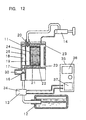
- Fig. 12 is a cross-sectional view to illustrate the overall structure of a catalytic combustion apparatus of this example.
- the valve as described in each of the above-described examples comprises a solenoid valve 34 and a control apparatus 35.
- the control apparatus 35 further comprises a timer circuit 36 and a relay circuit 37.
- the apparatus is controlled in a manner such that the solenoid valve 34 is temporarily closed by the timer circuit 36 and the relay circuit 37 for a certain period of time after an ignition device 14 has operated, and is reopened after a predetermined period of time has elapsed.
- Adoption of the above configuration enables extinction of a flame without fail after a catalyst for combustion 22 has been heated and stable transition to catalytic combustion.
- Fig. 13 is a cross-sectional view to illustrate the overall structure of a catalytic combustion apparatus of this example.
- a quantity-of-flow adjustable means 38 is provided on a valve 13.
- the quantity-of-flow adjustable means 38 has a cock 38a. In this example, by manually opening and closing the cock 38a, the quantity of fuel gas to be supplied from a fuel tank 12 can be adjusted.
- the cock 38a is fully opened when igniting so as to make the quantity of the fuel gas to be supplied from the fuel tank 12 to the maximum thereby lowering the excess air ratio and making ignition easy.
- the quantity of the fuel gas to be supplied from the fuel tank 12 is reduced by closing the cock 38a thereby increasing the excess air ratio. As a result, the flame spontaneously disappears and transition to catalytic combustion is quickly effected.
- Fig. 14 is a cross-sectional view to illustrate the overall structure of a catalytic combustion apparatus of this example.
- a temperature detecting means 40 is provided in a combustion chamber 21.
- a thermistor is used as the temperature detecting means 40 in this example.
- Detected temperature information from the temperature detecting means 40 is transmitted to a control apparatus 39.
- the control apparatus 39 has a relay circuit 37 and a temperature detecting circuit 41.
- the control apparatus 39 Upon detecting that the temperature of a catalyst for combustion 22 has reached catalytic combustion enabling temperature based on the detected temperature information from the temperature detecting means 40, the control apparatus 39 controls a solenoid valve 34 so it is temporarily closed. As a result, the fuel gas supplied from a fuel tank 12 is suspended at the time the temperature of the catalyst for combustion 22 has reached the catalytic combustion enabling temperature. Accordingly, the flame burning in a firing chamber 19 is automatically extinguished thereby assuring transition to catalytic combustion.
- a downsized and thin catalytic combustion apparatus is realized in which ignition and transition to catalytic combustion are performed with stability and certainty.
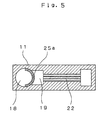
- FIG. 15 is a cross-sectional view of a combustor of a catalytic combustion apparatus of this example.
- an exhaust port 23 is provided on the combustor 11 at a position not overlapping a combustion chamber 21 and displaced in a direction opposite the direction of ejection of a mixed gas to a mixing chamber 19.
- the exhaust gas produced by catalytic combustion and to be exhausted from the exhaust port 23 will reach the exhaust port 23 while making contact with the combustion chamber 21.
- the amount of heat of the exhaust gas is absorbed by the combustion chamber 21, or is used to increase the temperature of the combustion chamber 21, the temperature of the exhaust gas is reduced.
- that portion of the mixed gas which is powerful is made far from the exhaust port 23 and that portion of the mixed gas which is weak is made near to the exhaust port 23 thereby allowing the mixed gas to uniformly pass through a catalyst for combustion 22.
- a combustor 11 has a burner port area adjustable means 42 for adjusting the area of a burner port 25. Also, the burner port area adjustable means 42 is operable with a signal from a temperature detecting means 43 provided in the vicinity of the burner port 25.
- the burner port area adjustable means 42 comprises an L-shaped adjustable plate 42 and a tension spring 42b. On the adjustable plate 42 are provided the same number and size of adjustable holes 42c as that of the burner port 25.
- the temperature detecting means 43 comprises a case 43a, a bimetal 43b and an operating rod 43c.
- the area of the aperture of the burner port 25 is reduced.
- the flame formed on the burner port 25 disappears. Consequently, the catalyst for combustion 22 can easily shift to catalytic combustion.
- the temperature of the heat sensitive rod 43d decreases, the bimetal 43d flips back again, and the adjustable plate 42a returns to its original position by the restoring force of the tension spring 42b.
- Fig. 18 is a cross-sectional view to illustrate the structure of a combustor of this example.
- a catalyst for combustion 22 is affixed in a combustion chamber 21 with a space 32 between itself and the inner wall of the combustion chamber 21. To be more specific, it is affixed between a pair of square C-shaped spacers 31 provided on the inner wall 21a of the combustion chamber 21.
- Fig. 19 and Fig. 20 are cross-sectional views to illustrate the configurations of a combustion chamber of this example.
- a catalyst for combustion 22 is provided with a thickness adjustable means 33.
- the thickness adjustable means 33 is composed of a pillar-shaped adjustable rod 33a having an oval cross-section.
- the catalyst for combustion 22 comprises two catalysts, namely, a first catalyst 22b and a second catalyst 22c disposed in a manner such that the adjustable rod 33a is sandwiched between them.
- the major axis of the adjustable rod 33a is in the horizontal direction, the thickness of the catalyst for combustion 22 becomes thin as illustrated in Fig. 19 , whereas, when in the vertical direction, the thickness becomes thick as illustrated in Fig. 20 . In this way, the thickness of the catalyst for combustion 22 can be freely varied by rotating the adjustable rod 33a.
- the quantity of heat generated by the catalyst for combustion 22 and conducted to a combustor 11 can be adjusted by adjusting the space 32 between the inner wall 21a of a combustion chamber 21 and the catalyst for combustion 22 thereby providing a catalytic combustion apparatus with a wide temperature control range.
- Fig. 21 is a cross-sectional view to illustrate a catalytic combustion apparatus of this example.
- Numeral 51 is a gas tank for storing liquefied petroleum gas such as butane and propane.
- a fuel gas inside the gas tank 51 is ejected from a gas nozzle 53 via a gas passage 52.
- a valve (not shown) for adjusting quantity of gas flow is provided between the gas tank 51 and the gas nozzle 53.
- the fuel gas ejected from the gas nozzle 53 draws in air from an air intake 54 by the ejection effect of the gas flow and is mixed with air in a mixing chamber 55.
- the exit of the mixing chamber 55 communicates with a straight cylindrical gas passage 56.
- a side of the straight cylindrical gas passage 56 communicates with a combustion chamber 58 which has a catalytic body 57.
- the combustion chamber 58 is disposed inside the straight cylindrical gas passage 56.
- an end portion of the combustion chamber 58 is positioned at a distance D inward from an end portion of a straight cylindrical gas passage 56.
- the catalytic body 57 is of a configuration as illustrated in Fig. 22.
- Fig. 22 is a perspective view to illustrate the shape of a catalytic body used in this exemplary example.
- a continuously corrugated thin sheet of metal consisting of stainless steel and the like is used as the carrier of the catalyst.
- a platinum group metal or an oxide of metals such as nickel, cobalt, iron, manganese, or chromium is used as the catalyst.
- a platinum group metal such as platinum, palladium, or rhodium. As illustrated in Fig.
- the catalytic body 57 is formed in the shape of a flat plate in a manner such that the planer area as represented by width A x length B is greater than the side area as represented by width A x thickness B.
- this catalyst carrier can be easily formed by processing a 0.05 to 0.1 mm thick stainless steel foil, for example.
- the catalyst carrier is one which is easy of continuous processing and is superior in mass producibility.
- the catalyst carrier is of a continuous corrugated configuration, a large surface area per unit volume is obtainable. That is, improvement in catalytic performance can be expected.
- Fig. 23 is a cross-sectional view of a section housing the above described catalytic body 57.
- the corrugated portion "a" functions as a gas passage.
- the combustion gas flows sideways passing this gas passage (hereafter called gas passage "a"). Also, the combustion gas undergoes catalytic combustion while it passes the gas passage "a”.
- an ignition device 59 is provided on the side opposite to the entrance of the combustion chamber 58.
- the ignition device 59 is operated to generate a spark on a plug 60 on the tip.
- a flame is formed downstream the catalytic body 57 by the spark, and the catalytic body 57 is heated by the flame.
- catalytic combustion begins on the surface of the catalytic body 57 and the flame disappears.
- the mixed gas supplied to the combustion chamber 58 undergoes catalytic reaction over the entire surface of the catalytic body 57 and generates heat as it passes the gas passage "a" of the catalytic body 57, and the combustion gas after reaction is exhausted from an exhaust port 61.
- the amount of combustion of a catalytic combustion apparatus is determined by the area (cross-sectional area) of the entrance of the catalytic body for the mixed gas if the catalytic material and the surface area of the entire catalytic body are the same. Consequently, when simply only the thickness of the catalytic body is reduced, the area of entrance is also reduced thus making it unable to obtain equivalent combustion characteristic and resulting in a poor combustion rate. For this reason, in this example, entrance area is secured by increasing the width A to compensate for the reduction in the thickness T of the catalytic body 57. As a result, according to the present example, the thickness can be reduced without reducing the combustion characteristic . Furthermore, as the catalytic body 57 is configured by continuous processing of a thin metal sheet as described before thereby to provide a large surface area per unit volume, further downsizing is enabled when compared with the prior art.
- the ejection velocity of the fuel gas ejected from the nozzle 53 is on the order of several 100 m/sec and the velocity of flow of the mixed gas flowing out from the mixing chamber 55 is also very high.
- a diffuser is provided at the exit of the mixing chamber 55 to gradually widen the area of the passage thereby making the flow velocity uniform.
- a longer diffuser is needed as the width of the entrance of the combustion chamber 58 increases, thereby resulting in a catalytic combustion apparatus having longer length and larger width.
- a communicating straight cylindrical gas passage 56 is provided at the exit of the mixing chamber 55 as has been described, and an entrance to the combustion chamber 58 is formed on a side of the straight cylindrical gas passage 56 so as to communicate with the entrance.
- the positional relation between the mixing chamber 55 and the catalytic body 57 is not serial but parallel.
- the mixed gas to be supplied to the combustion chamber 58 will become one in which the fuel gas and air are more uniformly mixed during the time the static pressure rises. Also, the distribution of flow velocity of the mixed gas at the entrance of the combustion chamber 58 will become uniform thereby enabling uniform supply of the mixed gas to the catalytic body 57.
- the catalytic combustion apparatus of the present example provides combustion heat of 60 watts or higher when the size is 6 mm in thickness and 50 mm in length. Consequently, when it is used in a warming cloth to be worn for warming the body, for example, there will be no feeling of wrongness and a product with superior portability may be realized.
- an apparatus with combustion heat on the order of 10 watts can be rightfully configured smaller and thinner than the above-mentioned dimension thus enabling use in small warmers such as gloves, shoes, or socks, for warming fingers of the hands or feet, or in thermotherapy curing device for treatment by applying the hot spot to arbitrary effective points.
- a gas resistant body 62 made of metal mesh or expanded metal and the like is provided at the exit of the mixing chamber 55 as illustrated in Fig. 21 .
- the gas resistant body 62 reduces the flow velocity of the mixed gas coming out from the mixing chamber 55 thereby reducing the flow velocity inside the straight cylindrical gas passage 56.
- the distribution of flow velocity of the mixed gas at the entrance of the combustion chamber 58 can be made further uniform.
- the diameter of the straight cylindrical gas passage 56 can be made smaller thereby enabling reduction of the overall size of the combustion apparatus.
- Fig. 24(a) is an exploded perspective view of a catalytic body 64 employed in a catalytic combustion apparatus of the present example.
- Fig. 24(b) is an assembled perspective view of the catalytic body 64.
- the catalytic body 64 is comprised of corrugated sheets 65 and 65' made by continuously folding thin metal sheet of stainless steel and the like and a flat plate 66 of thin metal sheet.
- the corrugated sheets 65 and 65' are made of 0.05 mm thick thin metal sheet and the flat plate 66 is made of 0.1 mm thick thin metal sheet.
- a catalyst carrier is configured by stacking by spot welding, for example, one or more of these into a multilayer structure.
- the catalyst supported by this catalyst carrier is the same as described in the first example. Similar to the description in the first example, the catalytic body 64 is of flat plate configuration in which the planer area is greater than the cross-sectional area. Also, when housed in a combustion chamber 58, the waved portion forms a gas passage along which a mixed gas flows in the lateral direction.
- the surface area per unit volume can be made greater than the configuration described in the first example. As a result, when the size of the catalytic body is the same, larger amount of combustion can be obtained.
- the flat plate 66 will not come into contact with the inner wall of the combustion chamber 58. Consequently, when adjusting the temperature of the flat plate 66 which has risen higher than the temperature of the corrugated sheets 65 and 65' by turning on and off the fuel gas, it is easy to maintain active temperature of the catalyst. That is, dying of combustion is made difficult to take place.
- the temperature difference between upstream and downstream of the mixed gas undergoing catalytic combustion on the catalytic body 64 is made smaller by the heat unifying action of the flat plate 66. Accordingly, the present example is advantageous to the life of the catalytic body 64, too.
- the corrugated sheets 65 and 65' were configured with 0.05 mm thick thin metal sheets and the flat plate 66 with a 0.1 mm thick thin metal sheet, the thickness is not restricted to these values.
- Fig. 25 is a perspective view to illustrate configuration of a catalytic body 67 employed in a catalytic combustion apparatus.
- a corrugated sheet 68 made by folding thin metal sheet in the form of continuous waves
- a corrugated sheet 70 made similarly
- a corrugated sheet 72 made similarly
- a flat plate 69 made of thin metal sheet
- a flat plate 71 made similarly.
- a multilayer metal catalyst is made by joining these materials by spot welding, for example.
- an amount of combustion approximately 1.5 times that of the configuration described in the twelfth example is obtained.
- the entrance area for a mixed gas and the surface area of the catalyst can be enlarged by increasing the number of stacked layers, and catalytic bodies with different amount of combustion can be fabricated by increasing or decreasing only the number of components for configuring the catalytic body. Consequently, standardization of components is made easy thus enabling low cost manufacturing.
- Fig. 26 is a cross-sectional view to illustrate the configuration of a catalytic combustion apparatus of the present example.
- Numeral 81 is a gas tank for storing liquefied petroleum gas such as butane or propane.
- the fuel gas inside the gas tank 81 is ejected from an ejection outlet 83a of a nozzle 83 via a gas passage 82.
- a control valve 84 for adjusting gas flow rate is provided between the gas tank 81 and the nozzle 83.
- the fuel gas ejected from the ejection outlet 83a draws in air through an air intake 85 and is mixed with air in a mixing chamber 86.
- the exit of the mixing chamber 86 communicates with a roughly cylindrical gas passage 87.
- a side of the cylindrical gas passage 87 communicates with a combustion chamber 90 having a catalytic body 89 via a firing chamber 88 which is disposed adjacent to the side of the gas passage 87.
- the catalytic body 89 has a honeycomb cross-section as illustrated by a side view of Fig. 27 , for example, and supports as a catalyst a platinum group metal or oxide of such metals as nickel, iron, manganese, or chromium on a carrier formed by corrugating thin metal sheets of stainless steel and the like.
- the fuel gas mixed with air undergoes catalytic combustion by catalytic action while it passes inside the catalytic body 89 after passing through the gas passage 87 and the firing chamber 88.
- an ignition device 91 is provided on the upper part of the firing chamber 88.
- a spark high voltage electric discharge spark
- a plug 91a on the tip by operating the ignition device 91.
- a flame is formed inside the firing chamber 88, and the catalytic body 89 is heated by the flame.
- Numeral 92 is a high tension wire to supply electricity to the ignition device 91.
- Numeral 94 is a temperature detecting means for detecting the temperature of the combustion chamber 90 and comprises a thermistor, thermocouple and the like, and is connected to a control unit 95.
- the control unit 95 is designed in a manner such that it controls the quantity of ejection of the fuel gas by driving a control valve 84 depending on the output from the temperature detecting means 94 and adjusts the temperature of the combustion chamber 90.
- the combustion chamber 90, the firing chamber 88, and the gas passage 87, etc. comprise two components divided by a plane parallel to the direction of flow of the mixed gas, namely, a lower base 96 and an upper base 97.
- Numeral 98 is a nozzle unit that integrates the air intake 85, the mixing chamber 86, and the nozzle 83 and is made by inserting the nozzle 83 into a cast component. It is also possible to configure it as an integral unit entirely by cutting work. In this example, as illustrated in Figs.
- the shape of the lower base 96 and the upper base 97 can be simplified thereby making processing easy, allowing reduction of the material thickness to a minimum thus enabling downsizing and thinner design.
- the nozzle unit 98 itself which requires a high degree of precision processing is made easier to process, suggesting the possibility of further downsizing by configuring an integral unit by cutting process of everything as described before.
- the combustion chamber 90 is divided into the lower base 96 and the upper base 97 by a plane roughly in parallel to the direction of ejection of the nozzle, the configuration for processing of the combustion chamber 90 section is greatly simplified thereby making processing easy, allowing reduction of the material thickness to a minimum thus achieving a low profile.
- combustion chamber 90 section is divided into upper and lower units, housing of the catalytic body 89 during assembly is made easy. Also, the assembling of the nozzle unit 98, the ignition device 91, and the temperature detecting means 94 is likewise easily done. Especially, as the temperature detecting means 94 has to detect the temperature of the combustion chamber 90 through heat conduction, although it is a general practice to fix it by pressing with a separate component made of a good heat conductor to ensure temperature detection, structure for fixing can be simplified by securing with the lower base 96 and the upper base 97 while sandwiching as in this configuration and temperature detection with higher reliability is assured.
Landscapes
- Engineering & Computer Science (AREA)
- Chemical & Material Sciences (AREA)
- Combustion & Propulsion (AREA)
- Mechanical Engineering (AREA)
- General Engineering & Computer Science (AREA)
- Chemical Kinetics & Catalysis (AREA)
- Gas Burners (AREA)
- Spray-Type Burners (AREA)
Claims (17)
- Katalytische Verbrennungsvorrichtung, die umfasst:einen Durchlass (16, 17, 52, 82, 87) zum Erzeugen eines Gemischs aus Luft und Brennstoffgas;eine Brennkammer (21, 58, 90), die in einer ersten Richtung, die im Allgemeinen quer zu einer Richtung ist, in der die Luft und das Brennstoffgas in den Durchlass (16, 17, 52, 82, 87) eingeleitet werden sollen, in Fluidverbindung mit dem Durchlass (52, 82, 87) steht, um das Gemisch aus Luft und Brennstoffgas aus dem Kanal in der ersten Richtung aufzunehmen;einen Katalysator (22, 64) für Verbrennung innerhalb der Brennkammer (21, 58, 90);eine Zündkammer (19, 88), die in der ersten Richtung in Fluidverbindung mit dem Durchlass (16, 17, 52, 82, 87) steht und in der ersten Richtung in Fluidverbindung mit der Brennkammer (21, 58, 90) steht, wobei die Brennkammer (21, 58, 90) in der ersten Richtung über die Brennkammer (19) in Fluidverbindung mit dem Durchlass steht; undeinen Brennerkanal (25) zwischen dem Durchlass (16, 17, 52, 82, 87) und der Zündkammer (19, 88), wobei der Brennerkanal (25) eine Platte mit Durchgangslöchern umfasst und der Durchlass (15) in der ersten Richtung über die Durchgangslöcher (29c) in Fluidverbindung mit der Zündkammer (19, 88) steht,dadurch gekennzeichnet, dassein Teil des Katalysators (22a) für Verbrennung in die Zündkammer (19) hinein vorsteht.
- Katalytische Verbrennungsvorrichtung nach Anspruch 1, wobei die Platte ein Netz umfasst, das einen Katalysator (25a) trägt.
- Katalytische Verbrennungsvorrichtung nach Anspruch 2, wobei der Durchlass (16, 17, 52, 82, 87) wenigstens teilweise durch eine Wand gebildet wird und ein Teil des Netzes in Kontakt mit der Wand ist.
- Katalytische Verbrennungsvorrichtung nach Anspruch 1, wobei der Durchlass (16, 17, 52, 82, 87) einen Einlass enthält, über den Luft und Brennstoffgas in den Durchlass (52, 82, 87) eingeleitet werden sollen, die Zündkammer (19, 88) wenigstens teilweise durch eine Wand gebildet wird und die Vorrichtung des Weiteren eine Zündeinrichtung (14) an der Wand an einer Position umfasst, die dem Einlass gegenüberliegt.
- Katalytische Verbrennungsvorrichtung nach Anspruch 1, die des Weiteren umfasst:einen Brenner (11), der den Durchlass (16, 17, 52, 82, 87), die Zündkammer (19, 88) und die Brennkammer (21, 58, 90) einschließt;einen Brennstoffbehälter (12), der in Fluidverbindung mit dem Brenner steht, um dem Brenner Brennstoffgas zuzuführen;eine Zündeinrichtung (14), die funktional mit dem Brenner verbunden ist, um das Brennstoffgas in dem Brenner zu zünden; undein Magnetventil (38), das zwischen dem Brennstoffbehälter (12) und dem Brenner angeordnet ist, um die Zufuhr von Brennstoffgas von dem Brennstoffbehälter zu dem Brenner zu steuern, wobei das Magnetventil (38) innerhalb eines vorgegebenen Zeitraums geschlossen sein soll, nachdem die Zündeinrichtung (14) das Brennstoffgas in dem Brenner (11) gezündet hat, so dass die Zufuhr von zusätzlichem Brennstoffgas von dem Brennstoffbehälter (12) zu dem Brenner (11) verhindert wird, und anschließend das Magnetventil (38) wieder geöffnet werden soll, um zusätzliche Zufuhr von Brennstoffgas von dem Brennstoffbehälter (12) zu dem Brenner zuzulassen.
- Katalytische Verbrennungsvorrichtung nach Anspruch 1, die des Weiteren umfasst:einen Brenner (11), der den Durchlass (16, 17, 52, 82, 87), die Zündkammer (19, 88) und die Brennkammer einschließt und des Weiteren einen Lufteinlass enthält;eine Zündeinrichtung (14, 85), die funktional mit dem Brenner verbunden ist, um Brennstoffgas in dem Brenner zu zünden; undeinen Lufteinlass-Verschluss (27), der an dem Lufteinlass (30, 54) des Brenners angeordnet ist, um die Zufuhr von Luft in den Brenner zu steuern, wobei der Lufteinlass-Verschluss (27) innerhalb eines vorgegebenen Zeitraums betätigt werden soll, nachdem die Zündeinrichtung (14, 91) das Brennstoffgas in dem Brenner (11) gezündet hat, so dass die Zufuhr von Luft in den Brenner (11) gesteuert wird.
- Katalytische Verbrennungsvorrichtung nach Anspruch 1, die des Weiteren umfasst:einen Brenner (11), der den Durchlass (16, 17, 52, 82, 87), die Zündkammer (19, 88) und die Brennkammer einschließt;eine Zündvorrichtung (91), die funktional mit dem Brenner verbunden ist, um Brennstoffgas in dem Brenner zu zünden; undeine Struktur, die funktional mit dem Brennerkanal (25) verbunden ist, um eine wirksame Fläche der Durchgangslöcher so zu regulieren, dass die Zufuhr des Gemischs aus Luft und Brennstoffgas in die Zündkammer (19, 88) über den Durchlass (16, 17, 52, 82, 87) gesteuert werden kann, wobei die Struktur innerhalb eines vorgegebenen Zeitraums betätigt werden soll, nachdem die Zündeinrichtung (91) das Brennstoffgas in dem Brenner (11) gezündet hat, so dass die Zufuhr des Gemischs aus Luft und Brennstoffgas in die Brennkammer (19, 88) über den Durchlass (16, 17, 52, 82, 87) gesteuert wird.
- Katalytische Verbrennungsvorrichtung nach Anspruch 7, wobei die Struktur zum Regulieren der wirksamen Fläche der Durchgangslöcher eine bewegliche Platte umfasst, die Durchgangslöcher hat, die den Durchgangslöchern der Platte der Brennerkanals (25) entsprechen, so dass die Zufuhr des Gemischs aus Luft und Brennstoffgas in die Zündkammer (19, 88) über den Durchlass (16, 17, 52, 82, 87) gesteuert werden kann, indem die bewegliche Platte relativ zu der Platte des Brennerkanals (25) bewegt wird, so dass die Durchgangslöcher der beweglichen Platte auf die Durchgangslöcher der Platte des Brennerkanals ausgerichtet werden oder nicht auf die Durchgangslöcher der Platte des Brennerkanals ausgerichtet werden.
- Katalytische Verbrennungsvorrichtung nach Anspruch 1, die des Weiteren umfasst:einen Brenner (11), der den Durchlass (52, 82, 87), die Zündkammer (19, 88) und die Brennkammer (21, 58, 90) einschließt und des Weiteren einen Temperatursensor (40, 94) einschließt;einen Brennstoffbehälter (81), der in Fluidverbindung mit dem Brenner steht, um dem Brenner Brennstoffgas zuzuführen; undein Magnetventil (34), das zwischen dem Brennstoffbehälter (12, 81) und dem Brenner angeordnet ist, um die Zufuhr von Brennstoffgas von dem Brennstoffbehälter (12, 81) zu dem Brenner zu steuern, wobei das Magnetventil (34) in Reaktion auf eine durchden Temperatursensor (40, 94) erfasste Temperatur vorübergehend geschlossen werden soll.
- Katalytische Verbrennungsvorrichtung nach Anspruch 1, die des Weiteren umfasst:einen Brenner (11), der den Durchlass (52, 82, 87), die Zündkammer (19, 88) und die Brennkammer einschließt und des Weiteren einen Lufteinlass (54) sowie einen Temperatursensor (40, 94) einschließt; undeinen Lufteinlass-Verschluss (27), der an dem Lufteinlass (26) des Brenners angeordnet ist, um die Zufuhr von Luft in den Brenner zu steuern, wobei der Lufteinlass-Verschluss (27) in Reaktion auf eine durch den Temperatursensor (40, 94) erfasste Temperatur betätigt werden soll.
- Katalytische Verbrennungsvorrichtung nach Anspruch 1, die des Weiteren umfasst:einen Brenner (11), der den Durchlass (52, 82, 87), die Zündkammer (19, 88) und die Brennkammer (21, 59, 90) einschließt und des Weiteren einen Temperatursensor (40, 94) einschließt; undeine Struktur, die funktional mit dem Brennerkanal (29) verbunden ist, um eine wirksame Fläche der Durchgangslöcher so zu regulieren, dass die Zufuhr des Gemischs aus Luft und Brennstoffgas in die Zündkammer (19, 88) über den Durchlass (52, 82, 87) gesteuert werden kann, wobei die Struktur in Reaktion auf eine durch den Temperatursensor (40, 94) erfasste Temperatur betätigt werden soll.
- Katalytische Verbrennungsvorrichtung nach Anspruch 11, wobei die Struktur zum Regulieren der wirksamen Fläche der Durchgangslöcher eine bewegliche Platte umfasst, die Durchgangslöcher hat, die den Durchgangslöchern der Platte der Brennerkanals (25) entsprechen, so dass die Zufuhr des Gemischs aus Luft und Brennstoffgas in die Zündkammer (19, 88) über den Durchlass (52, 82, 87) gesteuert werden kann, indem die bewegliche Platte relativ zu der Platte des Brennerkanals (29) bewegt wird, so dass die Durchgangslöcher der beweglichen Platte auf die Durchgangslöcher der Platte des Brennerkanals ausgerichtet werden oder nicht auf die Durchgangslöcher der Platte des Brennerkanals ausgerichtet werden.
- Katalytische Verbrennungsvorrichtung nach Anspruch 1, wobei der Katalysator für Verbrennung eine erste Fläche enthält, die in einer Ebene (56) eingeschlossen ist, die erste Fläche eine Länge und eine Breite hat, die katalytische Verbrennungsvorrichtung des Weiteren eine zweite Fläche enthält, die in einer Ebene eingeschlossen ist, die zweite Fläche eine Breite hat, die sich quer zu der Breite der ersten Fläche erstreckt und kleiner ist als die Breite der ersten Fläche, und die zweite Fläche eine Länge hat, die sich parallel zu der Länge der ersten Fläche erstreckt und genauso groß ist wie die Länge der ersten Fläche, und die katalytische Verbrennungsvorrichtung des Weiteren Durchlasse enthält, die sich entlang der Breite der ersten Fläche erstrecken, um den Strom von Gas durch die Durchlasse (52, 82, 87) hindurch zuzulassen.
- Katalytische Verbrennungsvorrichtung nach Anspruch 1, wobei der Katalysator für Verbrennung einen Katalysator umfasst, der von einem Katalysatorhalter getragen wird, der einen Träger aus gewelltem dünnen Metall umfasst, der abwechselnde Spitzen und Täler aufweist, die Spitzen in einer Ebene eingeschlossen sind und durch einen Bereich begrenzt werden, der durch eine Breite der Spitzen sowie eine erste Länge von einer ersten der Spitzen zu einer letzten der Spitzen definiert wird, der Träger aus gewelltem dünnen Metall des Weiteren eine Seitenfläche aufweist, die eine Breite hat, die kleiner ist als die Breite der Spitzen und sich quer zu dieser erstreckt, und des Weiteren eine Länge hat, die sich parallel zu der ersten Länge erstreckt und genauso groß ist wie diese, und der Bereich zwischen den Spitzen und Tälern Durchlasse (52, 82, 87) bildet, die sich entlang der Breite der Spitzen erstrecken, um den Strom von Gas durch die Durchlasse (52, 82, 87) hindurch zuzulassen.
- Katalytische Verbrennungsvorrichtung nach Anspruch 14, wobei der Katalysatorhalter des Weiteren eine flache Platte (69, 71) auf den Spitzen und einen weiteren Träger aus gewelltem dünnen Metall auf der flachen Platte (69, 71) enthält.
- Katalytische Verbrennungsvorrichtung nach Anspruch 1, wobei der Durchlass (52, 82, 87), die Zündkammer (19, 88) und die Brennkammer (21, 58, 90) zwischen mehreren Komponenten ausgebildet sind, die durch eine Ebene voneinander getrennt sind, die sich im Allgemeinen parallel zu der Richtung, in der die Luft und das Brennstoffgas in den Durchlass eingeleitet werden sollen, sowie im Allgemeinen quer zu der ersten Richtung erstreckt.
- Katalytische Verbrennungsvorrichtung nach Anspruch 16, wobei die mehreren Komponenten die Brennkammer bilden und ein Komponenten-Körper, der eine Mischkammer und eine Düse integral bildet, zwischen den mehreren Komponenten so eingeschlossen und befestigt ist, dass der Durchlass (52, 82, 87) über die Mischkammer in Fluidverbindung mit der Düse steht.
Applications Claiming Priority (9)
| Application Number | Priority Date | Filing Date | Title |
|---|---|---|---|
| JP36100898A JP3937621B2 (ja) | 1998-12-18 | 1998-12-18 | 触媒燃焼装置 |
| JP36100898 | 1998-12-18 | ||
| JP10363262A JP2000186804A (ja) | 1998-12-21 | 1998-12-21 | 触媒燃焼装置 |
| JP36326298 | 1998-12-21 | ||
| JP08330999A JP3858508B2 (ja) | 1999-03-26 | 1999-03-26 | 触媒燃焼装置 |
| JP8330999 | 1999-03-26 | ||
| JP16488199 | 1999-06-11 | ||
| JP16488199A JP3855537B2 (ja) | 1999-06-11 | 1999-06-11 | 触媒燃焼装置 |
| PCT/JP1999/007090 WO2000037854A1 (en) | 1998-12-18 | 1999-12-17 | Catalyst combustion device |
Publications (3)
| Publication Number | Publication Date |
|---|---|
| EP1058055A1 EP1058055A1 (de) | 2000-12-06 |
| EP1058055A4 EP1058055A4 (de) | 2005-05-18 |
| EP1058055B1 true EP1058055B1 (de) | 2009-10-14 |
Family
ID=27466812
Family Applications (1)
| Application Number | Title | Priority Date | Filing Date |
|---|---|---|---|
| EP99959870A Expired - Lifetime EP1058055B1 (de) | 1998-12-18 | 1999-12-17 | Katalytische verbrennungseinrichtung |
Country Status (5)
| Country | Link |
|---|---|
| US (1) | US6394789B1 (de) |
| EP (1) | EP1058055B1 (de) |
| CN (1) | CN100368728C (de) |
| DE (1) | DE69941535D1 (de) |
| WO (1) | WO2000037854A1 (de) |
Families Citing this family (17)
| Publication number | Priority date | Publication date | Assignee | Title |
|---|---|---|---|---|
| DE19901145A1 (de) * | 1999-01-14 | 2000-07-20 | Krieger Gmbh & Co Kg | Als Flächenstrahler ausgebildeter Infrarot-Strahler |
| EP1126216A4 (de) * | 1999-08-19 | 2009-10-28 | Panasonic Corp | Katalytische verbrennungseinrichtung und brennstoffverdampfungseinrichtung |
| SE514682C2 (sv) * | 2000-02-24 | 2001-04-02 | Swep Int Ab | Anordning för katalytisk behandling av strömmande medier, innefattande en plattvärmeväxlare |
| US20040081871A1 (en) * | 2002-10-28 | 2004-04-29 | Kearl Daniel A. | Fuel cell using a catalytic combustor to exchange heat |
| JP2005055098A (ja) * | 2003-08-06 | 2005-03-03 | Denso Corp | 触媒反応ヒータ |
| IES20040762A2 (en) * | 2003-11-14 | 2005-09-21 | Oglesby & Butler Res & Dev Ltd | A converting device for converting fuel gas to heat and a gas powered heating device |
| KR100820233B1 (ko) * | 2006-10-31 | 2008-04-08 | 한국전력공사 | 연소기 및 이를 포함하는 멀티 연소기, 그리고 연소방법 |
| SE539758C2 (en) * | 2014-12-04 | 2017-11-21 | Powercell Sweden Ab | Catalytic burner arragement |
| CN106642646A (zh) * | 2015-10-29 | 2017-05-10 | 青岛经济技术开发区海尔热水器有限公司 | 燃气热水器及其控制方法 |
| CN108151012B (zh) * | 2016-12-04 | 2019-07-26 | 中国科学院大连化学物理研究所 | 一种甲醇气化和催化燃烧装置及操作方法 |
| CN108019740A (zh) * | 2017-11-20 | 2018-05-11 | 徐州工程学院 | 一种生物质燃料锅炉装置及其工作方法 |
| CN111397219B (zh) * | 2018-01-18 | 2021-07-27 | 芜湖美的厨卫电器制造有限公司 | 用燃气进行燃烧的机器的控制设备和方法及燃气热水器 |
| CN108343949B (zh) * | 2018-03-21 | 2019-11-01 | 山东京博石油化工有限公司 | 一种催化辅助燃烧室的燃烧方法 |
| CN111322611A (zh) * | 2018-12-13 | 2020-06-23 | 偿丰企业有限公司 | 热能模块 |
| CN110180387A (zh) * | 2019-07-02 | 2019-08-30 | 苏州仕净环保科技股份有限公司 | 一种污染气源的高效处理系统 |
| CN111503649B (zh) * | 2020-04-28 | 2022-03-18 | 聊城集众环保科技有限公司 | 一种吸附浓缩型蓄热式催化燃烧装置 |
| CN115468186B (zh) * | 2022-08-31 | 2024-03-22 | 常德市三一机械有限公司 | 燃烧器点火设备、点火方法及沥青站 |
Family Cites Families (16)
| Publication number | Priority date | Publication date | Assignee | Title |
|---|---|---|---|---|
| JPS5864413A (ja) * | 1981-10-13 | 1983-04-16 | Matsushita Electric Ind Co Ltd | 触媒燃焼装置 |
| JPS5864412A (ja) * | 1981-10-13 | 1983-04-16 | Matsushita Electric Ind Co Ltd | 触媒燃焼装置 |
| US5346389A (en) * | 1989-02-24 | 1994-09-13 | W. R. Grace & Co.-Conn. | Combustion apparatus for high-temperature environment |
| US5403184A (en) * | 1992-05-20 | 1995-04-04 | Matsushita Electric Industrial Co., Ltd. | Exothermic apparatus |
| JP2724658B2 (ja) * | 1992-11-13 | 1998-03-09 | 松下電器産業株式会社 | 発熱装置 |
| JP2797840B2 (ja) * | 1992-06-09 | 1998-09-17 | 松下電器産業株式会社 | 触媒燃焼装置 |
| JP3221972B2 (ja) * | 1993-04-22 | 2001-10-22 | 松下電器産業株式会社 | 触媒とそれを用いた触媒燃焼装置 |
| EP0716263B1 (de) * | 1994-12-06 | 2002-10-09 | Matsushita Electric Industrial Co., Ltd. | Verbrennungsgerät |
| US5928427A (en) * | 1994-12-16 | 1999-07-27 | Hwang; Chul-Ju | Apparatus for low pressure chemical vapor deposition |
| CN2207204Y (zh) * | 1994-12-30 | 1995-09-13 | 李勇 | 燃气催化型阻火防爆器 |
| IT1282428B1 (it) * | 1995-08-01 | 1998-03-23 | Zeltron Spa | Sistema di controllo per bruciatore catalitico |
| JPH09170708A (ja) * | 1995-12-19 | 1997-06-30 | Matsushita Electric Ind Co Ltd | 触媒燃焼装置 |
| SE9602688L (sv) * | 1996-07-08 | 1998-01-09 | Volvo Ab | Katalytisk brännkammare, samt förfarande för tändning och reglering av den katalytiska brännkammaren |
| JPH1089616A (ja) * | 1996-09-20 | 1998-04-10 | Matsushita Electric Ind Co Ltd | 触媒燃焼装置 |
| JPH10204706A (ja) * | 1997-01-09 | 1998-08-04 | Matsushita Electric Ind Co Ltd | 暖房衣服 |
| JP3281287B2 (ja) * | 1997-05-13 | 2002-05-13 | 田中貴金属工業株式会社 | 燃焼触媒体及びこれを用いたファンヒータ |
-
1999
- 1999-12-17 CN CNB998029564A patent/CN100368728C/zh not_active Expired - Fee Related
- 1999-12-17 US US09/622,129 patent/US6394789B1/en not_active Expired - Fee Related
- 1999-12-17 WO PCT/JP1999/007090 patent/WO2000037854A1/ja not_active Ceased
- 1999-12-17 EP EP99959870A patent/EP1058055B1/de not_active Expired - Lifetime
- 1999-12-17 DE DE69941535T patent/DE69941535D1/de not_active Expired - Lifetime
Also Published As
| Publication number | Publication date |
|---|---|
| WO2000037854A1 (en) | 2000-06-29 |
| EP1058055A1 (de) | 2000-12-06 |
| EP1058055A4 (de) | 2005-05-18 |
| CN1291273A (zh) | 2001-04-11 |
| CN100368728C (zh) | 2008-02-13 |
| DE69941535D1 (de) | 2009-11-26 |
| US6394789B1 (en) | 2002-05-28 |
Similar Documents
| Publication | Publication Date | Title |
|---|---|---|
| EP1058055B1 (de) | Katalytische verbrennungseinrichtung | |
| EP2837884B1 (de) | Brenner | |
| US5403184A (en) | Exothermic apparatus | |
| US4455822A (en) | Device to ignite fuel injected in a rapidly flowing gaseous medium | |
| JP3855537B2 (ja) | 触媒燃焼装置 | |
| JP3858508B2 (ja) | 触媒燃焼装置 | |
| JP3937621B2 (ja) | 触媒燃焼装置 | |
| JP3858481B2 (ja) | 触媒燃焼器 | |
| JP2572055B2 (ja) | 触媒燃焼装置 | |
| JP3793815B2 (ja) | ガス燃焼装置 | |
| JP2724658B2 (ja) | 発熱装置 | |
| CA2891997C (en) | A combination heat exchanger and burner | |
| JP2932795B2 (ja) | 発熱装置 | |
| KR100303706B1 (ko) | 촉매연소아이론 | |
| JP3098132B2 (ja) | 発熱装置 | |
| JP2002106810A (ja) | 触媒燃焼器 | |
| JPS58129106A (ja) | 燃焼装置 | |
| JP2932798B2 (ja) | 発熱装置 | |
| JP3611381B2 (ja) | 燃焼器の制御装置および制御方法 | |
| JP2000186804A (ja) | 触媒燃焼装置 | |
| JPS586352A (ja) | 温風暖房装置 | |
| JP2001235115A (ja) | 燃焼装置 | |
| JPH1137412A (ja) | 燃焼装置 | |
| JPS6238602B2 (de) | ||
| JP2001201009A (ja) | 触媒燃焼装置 |
Legal Events
| Date | Code | Title | Description |
|---|---|---|---|
| PUAI | Public reference made under article 153(3) epc to a published international application that has entered the european phase |
Free format text: ORIGINAL CODE: 0009012 |
|
| 17P | Request for examination filed |
Effective date: 20000906 |
|
| AK | Designated contracting states |
Kind code of ref document: A1 Designated state(s): AT BE CH CY DE DK ES FI FR GB GR IE IT LI LU MC NL PT SE |
|
| RBV | Designated contracting states (corrected) |
Designated state(s): DE FR IT NL |
|
| A4 | Supplementary search report drawn up and despatched |
Effective date: 20050405 |
|
| RIC1 | Information provided on ipc code assigned before grant |
Ipc: 7F 23C 11/00 B Ipc: 7F 23D 14/28 B Ipc: 7F 23D 14/18 A |
|
| 17Q | First examination report despatched |
Effective date: 20060904 |
|
| RAP1 | Party data changed (applicant data changed or rights of an application transferred) |
Owner name: PANASONIC CORPORATION |
|
| GRAP | Despatch of communication of intention to grant a patent |
Free format text: ORIGINAL CODE: EPIDOSNIGR1 |
|
| RIC1 | Information provided on ipc code assigned before grant |
Ipc: F23C 13/06 20060101ALI20090407BHEP Ipc: F23D 14/28 20060101ALI20090407BHEP Ipc: F23D 14/18 20060101AFI20090407BHEP |
|
| RTI1 | Title (correction) |
Free format text: CATALYTIC COMBUSTION DEVICE |
|
| GRAS | Grant fee paid |
Free format text: ORIGINAL CODE: EPIDOSNIGR3 |
|
| GRAA | (expected) grant |
Free format text: ORIGINAL CODE: 0009210 |
|
| AK | Designated contracting states |
Kind code of ref document: B1 Designated state(s): DE FR IT NL |
|
| REF | Corresponds to: |
Ref document number: 69941535 Country of ref document: DE Date of ref document: 20091126 Kind code of ref document: P |
|
| PGFP | Annual fee paid to national office [announced via postgrant information from national office to epo] |
Ref country code: NL Payment date: 20091224 Year of fee payment: 11 |
|
| PGFP | Annual fee paid to national office [announced via postgrant information from national office to epo] |
Ref country code: IT Payment date: 20091217 Year of fee payment: 11 Ref country code: FR Payment date: 20100106 Year of fee payment: 11 |
|
| PLBE | No opposition filed within time limit |
Free format text: ORIGINAL CODE: 0009261 |
|
| STAA | Information on the status of an ep patent application or granted ep patent |
Free format text: STATUS: NO OPPOSITION FILED WITHIN TIME LIMIT |
|
| 26N | No opposition filed |
Effective date: 20100715 |
|
| PGFP | Annual fee paid to national office [announced via postgrant information from national office to epo] |
Ref country code: DE Payment date: 20101215 Year of fee payment: 12 |
|
| REG | Reference to a national code |
Ref country code: NL Ref legal event code: V1 Effective date: 20110701 |
|
| REG | Reference to a national code |
Ref country code: FR Ref legal event code: ST Effective date: 20110831 |
|
| PG25 | Lapsed in a contracting state [announced via postgrant information from national office to epo] |
Ref country code: FR Free format text: LAPSE BECAUSE OF NON-PAYMENT OF DUE FEES Effective date: 20110103 |
|
| PG25 | Lapsed in a contracting state [announced via postgrant information from national office to epo] |
Ref country code: IT Free format text: LAPSE BECAUSE OF NON-PAYMENT OF DUE FEES Effective date: 20101217 Ref country code: NL Free format text: LAPSE BECAUSE OF NON-PAYMENT OF DUE FEES Effective date: 20110701 |
|
| REG | Reference to a national code |
Ref country code: DE Ref legal event code: R119 Ref document number: 69941535 Country of ref document: DE Effective date: 20120703 |
|
| PG25 | Lapsed in a contracting state [announced via postgrant information from national office to epo] |
Ref country code: DE Free format text: LAPSE BECAUSE OF NON-PAYMENT OF DUE FEES Effective date: 20120703 |