EP1060470B1 - Procede et dispositif de calcul agile reparti pour des retards dans la formation de rayons et valeurs d'apodisation - Google Patents
Procede et dispositif de calcul agile reparti pour des retards dans la formation de rayons et valeurs d'apodisation Download PDFInfo
- Publication number
- EP1060470B1 EP1060470B1 EP99961927A EP99961927A EP1060470B1 EP 1060470 B1 EP1060470 B1 EP 1060470B1 EP 99961927 A EP99961927 A EP 99961927A EP 99961927 A EP99961927 A EP 99961927A EP 1060470 B1 EP1060470 B1 EP 1060470B1
- Authority
- EP
- European Patent Office
- Prior art keywords
- function
- receive
- apodization
- recited
- cordic
- Prior art date
- Legal status (The legal status is an assumption and is not a legal conclusion. Google has not performed a legal analysis and makes no representation as to the accuracy of the status listed.)
- Expired - Lifetime
Links
Images



Classifications
-
- G—PHYSICS
- G10—MUSICAL INSTRUMENTS; ACOUSTICS
- G10K—SOUND-PRODUCING DEVICES; METHODS OR DEVICES FOR PROTECTING AGAINST, OR FOR DAMPING, NOISE OR OTHER ACOUSTIC WAVES IN GENERAL; ACOUSTICS NOT OTHERWISE PROVIDED FOR
- G10K11/00—Methods or devices for transmitting, conducting or directing sound in general; Methods or devices for protecting against, or for damping, noise or other acoustic waves in general
- G10K11/18—Methods or devices for transmitting, conducting or directing sound
- G10K11/26—Sound-focusing or directing, e.g. scanning
- G10K11/34—Sound-focusing or directing, e.g. scanning using electrical steering of transducer arrays, e.g. beam steering
- G10K11/341—Circuits therefor
- G10K11/346—Circuits therefor using phase variation
-
- G—PHYSICS
- G01—MEASURING; TESTING
- G01S—RADIO DIRECTION-FINDING; RADIO NAVIGATION; DETERMINING DISTANCE OR VELOCITY BY USE OF RADIO WAVES; LOCATING OR PRESENCE-DETECTING BY USE OF THE REFLECTION OR RERADIATION OF RADIO WAVES; ANALOGOUS ARRANGEMENTS USING OTHER WAVES
- G01S15/00—Systems using the reflection or reradiation of acoustic waves, e.g. sonar systems
- G01S15/88—Sonar systems specially adapted for specific applications
- G01S15/89—Sonar systems specially adapted for specific applications for mapping or imaging
- G01S15/8906—Short-range imaging systems; Acoustic microscope systems using pulse-echo techniques
- G01S15/8993—Three dimensional imaging systems
-
- G—PHYSICS
- G01—MEASURING; TESTING
- G01S—RADIO DIRECTION-FINDING; RADIO NAVIGATION; DETERMINING DISTANCE OR VELOCITY BY USE OF RADIO WAVES; LOCATING OR PRESENCE-DETECTING BY USE OF THE REFLECTION OR RERADIATION OF RADIO WAVES; ANALOGOUS ARRANGEMENTS USING OTHER WAVES
- G01S7/00—Details of systems according to groups G01S13/00, G01S15/00, G01S17/00
- G01S7/52—Details of systems according to groups G01S13/00, G01S15/00, G01S17/00 of systems according to group G01S15/00
- G01S7/52017—Details of systems according to groups G01S13/00, G01S15/00, G01S17/00 of systems according to group G01S15/00 particularly adapted to short-range imaging
- G01S7/52046—Techniques for image enhancement involving transmitter or receiver
-
- G—PHYSICS
- G06—COMPUTING OR CALCULATING; COUNTING
- G06F—ELECTRIC DIGITAL DATA PROCESSING
- G06F7/00—Methods or arrangements for processing data by operating upon the order or content of the data handled
- G06F7/38—Methods or arrangements for performing computations using exclusively denominational number representation, e.g. using binary, ternary, decimal representation
- G06F7/48—Methods or arrangements for performing computations using exclusively denominational number representation, e.g. using binary, ternary, decimal representation using non-contact-making devices, e.g. tube, solid state device; using unspecified devices
- G06F7/544—Methods or arrangements for performing computations using exclusively denominational number representation, e.g. using binary, ternary, decimal representation using non-contact-making devices, e.g. tube, solid state device; using unspecified devices for evaluating functions by calculation
- G06F7/5446—Methods or arrangements for performing computations using exclusively denominational number representation, e.g. using binary, ternary, decimal representation using non-contact-making devices, e.g. tube, solid state device; using unspecified devices for evaluating functions by calculation using crossaddition algorithms, e.g. CORDIC
-
- G—PHYSICS
- G06—COMPUTING OR CALCULATING; COUNTING
- G06F—ELECTRIC DIGITAL DATA PROCESSING
- G06F7/00—Methods or arrangements for processing data by operating upon the order or content of the data handled
- G06F7/38—Methods or arrangements for performing computations using exclusively denominational number representation, e.g. using binary, ternary, decimal representation
- G06F7/48—Methods or arrangements for performing computations using exclusively denominational number representation, e.g. using binary, ternary, decimal representation using non-contact-making devices, e.g. tube, solid state device; using unspecified devices
- G06F7/544—Methods or arrangements for performing computations using exclusively denominational number representation, e.g. using binary, ternary, decimal representation using non-contact-making devices, e.g. tube, solid state device; using unspecified devices for evaluating functions by calculation
- G06F7/552—Powers or roots, e.g. Pythagorean sums
Definitions
- This invention generally relates to coherent imaging methods which apply a phased array antenna.
- the invention relates to beamforming techniques for use in ultrasound imaging systems.
- a medical ultrasound system forms an image by acquiring individual ultrasound lines (or beams).
- the lines are adjacent to each other and cover the target area to be imaged.
- Each line is formed by transmitting an ultrasonic pulse in a particular spatial direction and receiving the reflected echoes from that direction.
- the spatial characteristics of the transmitted wave and the characteristics of the receive sensitivity determine the quality of the ultrasound image. It is desirable that the ultrasound line gathers target information only from the intended direction and ignores targets at other directions.
- Conventional ultrasound imaging systems comprise an array of ultrasonic transducer elements which are used to transmit an ultrasound beam and then receive the reflected beam from the object being studied.
- Such scanning comprises a series of measurements in which the focused ultrasonic wave is transmitted, the system switches to receive mode after a short time interval, and the reflected ultrasonic wave is received, beamformed and processed for display.
- EP-A-0 782 126 Such a system is known from the European patent application EP-A-0 782 126.
- transmission and reception are focused in the same direction during each measurement to acquire data from a series of points along an acoustic beam or scan line.
- the receiver is dynamically focused at a succession of ranges along the scan line as the reflected ultrasonic waves are received.
- the array typically has a multiplicity of transducer elements arranged in one or more rows and driven with separate voltages.
- the individual transducer elements in a given row can be controlled to produce ultrasonic waves which combine to form a net ultrasonic wave that travels along a preferred vector direction and is focused in a selected zone along the beam.
- the beamforming parameters of each of the firings may be varied to provide a change in maximum focus or otherwise change the content of the received data for each firing, e.g., by transmitting successive beams along the same scan line with the focal zone of each beam being shifted relative to the focal zone of the previous beam.
- the beam with its focal zone can be moved in a plane to scan the object.
- a focused beam directed normal to the array is scanned across the object by translating the aperture across the array from one firing to the next.
- the transducer probe is employed to receive the reflected sound in a receive mode.
- the voltages produced at the receiving transducer elements are summed so that the net signal is indicative of the ultrasound reflected from a single focal zone in the object.
- this focused reception of the ultrasonic energy is achieved by imparting separate time delay (and/or phase shifts) and gains to the signal from each receiving transducer element. The time delays are adjusted with increasing depth of the returned signal to provide dynamic focusing on receive.
- the beamformer control is a significant contributor to the performance and cost of the system.
- Dynamic receive delay and apodization control must be generated for each beam and channel at a high rate. Often as many as 512 beam channels are required for a high-end system with an update rate as high as 10 MHz.
- Calculating delays and apodization for an ultrasound beamformer during dynamic reception requires complex calculations including transcendental functions. Normally image quality is traded off for cost by using second or third-order approximations for these functions.
- large memories are frequently used to store precalculated controls for predetermined beam positions and parameters. Using stored precalculated values limits the ability of the system to optimally readjust beam position or parameters dependent on scanning situations. Thus image quality is compromised to achieve faster control response times.
- Agility means the ability to change the beamforming setup for an entire imaging configuration in a time much less than 1 sec, where the setup includes vector phase center (aperture) positions, steering angles, f-numbers, and focal positions, and the imaging configuration includes all vectors (beams) displayed on the imaging console. Agility also means the ability to begin receive delay computation in mid-flight, i.e., immediately before a deep region of interest.
- controllers described in many patents use state machines. Unfortunately these state machines must begin running immediately after transmit. They cannot easily be reloaded for a different receive focus significantly after transmission. For some high-frame-rate applications, particularly for volumetric imaging, it is desirable to start reception just before echoes from a deep region of interest are received.
- at least one prior art method uses parameters which are beam and element dependent. This results in an extremely large number of parameters, involving functions such as square root and sine. This makes agility impossible.
- the present invention concerns a beamforming system according to claim 1, an imaging system according to claim 11, and a method for ultrasound beam forming according to claim 15.
- the present invention is an architecture for calculating beamformer time delays and apodization values in real-time by using a cordic rotator (hereinafter "cordic"), a simple multiplier-less device used for polar-Cartesian conversions.
- cordic a cordic rotator
- the use of the cordic to directly calculate the root-sum-of-squares without approximation or complex logic provides ideal performance and flexibility at low cost.
- the system may quickly re-optimize the beam positions and parameters without the need to recalculate large pre-stored memories or use rough approximations.
- cordic rotators are utilized in a very agile, efficient and precise method and means for calculating ultrasonic beamforming apodization weightings and time delays.
- Apodization weightings and time delays are calculated in a real-time, distributed and pipelined manner without the need for large memories or complex state machines. There are no inherent approximations. Precision may be easily controlled to be within the accuracy of the delay apparatus.
- the element positions are written into relatively small distributed memories. The element positions do not need to be reloaded except when the array geometry is changed. While imaging, a small number of parameters are broadcast before each transmission and during each reception.
- focal position(s) may include: focal position(s), multiplexer state(s), aperture position(s), aperture size(s) and vector angle(s).
- Simple logic including cordics, combines these parameters to produce beamforming time delays and apodization.
- Focal position and apertures may be changed very quickly for an entire image, in milliseconds.
- the receive focal positions do not need to start at the skin-line or follow a straight line, as required by state machine approaches. Reception focus can begin in mid-flight, and be warped to compensate for parallel beamforming methods.
- the array geometry may take any form; it is not restricted to the conventional linear, convex and phase arrays.
- the present invention can be incorporated in any ultrasound imaging system employing beamforming.
- Any ultrasound imaging system employing beamforming is one example of the foregoing.
- a B-mode ultrasound imaging system which will be generally described before disclosing in detail the preferred embodiment of the invention.
- a conventional B-mode ultrasound imaging system is generally depicted in FIG. 1.
- the system comprises a transducer array 2 consisting of a plurality of separately driven transducer elements 34, each of which produces a burst of ultrasonic energy when energized by a pulsed waveform produced by a transmitter 8 and sent through a set of transmit/receive (T/R) switches 6 switched to a transmit state and respective switches of a multiplexer 4 switched to a MUX state.
- T/R transmit/receive
- the ultrasonic energy reflected back to transducer array 2 from the object under study is converted to an electrical signal by each receiving transducer element 34 and applied separately to a receive beamformer 10 through the multiplexer switches 4 switched to the MUX state and the T/R switches 6 switched to a receive state.
- Transmitter 8 and receive beamformer 10 are operated under control of a host computer (master controller) 24.
- a complete scan is performed by acquiring a series of echoes in which transmitter 8 is gated ON momentarily to energize each transducer element 34 in the transmit aperture, and the subsequent echo signals produced by each transducer element 34 are applied to receive beamformer 10.
- the receive beamformer 10 combines the separate echo signals from each transducer element 34 to produce a single echo signal which is used to produce a line in an image on a display monitor 22.
- the receive beamformer's signal inputs are the low-level analog RF signals from the transducer elements 34.
- the receive beamformer is responsible for analog-to-digital conversion and for receive beamforming.
- the beamsummed signal is output to a demodulator 12, which converts the beamsummed signal into baseband in-phase I and quadrature Q receive beams.
- the I and Q acoustic data vectors from the demodulator 12 are sent to respective FIR filters 14 which are programmed with filter coefficients to pass a band of frequencies preferably centered at the fundamental frequency f 0 of the transmit waveform or a (sub)harmonic frequency thereof.
- vectors of filtered I and Q acoustic data are sent to a B-mode processor 16, which converts the I and Q acoustic data into a log-compressed version of the signal envelope.
- the B-mode function images the time-varying amplitude of the envelope of the signal as a gray scale.
- the envelope of a baseband signal is the magnitude of the vector which I and Q represent.
- the I,Q phase angle is not used in the B-mode display.
- the magnitude (i.e., intensity) of the signal is the square root of the sum of the squares of the orthogonal components, i.e., ( I 2 + Q 2 ) 1/2 .
- the B-mode amplitude data is output to a scan converter 18 comprising an acoustic line memory followed by an X-Y display memory.
- the acoustic line memory accepts the processed vectors of amplitude data and interpolates where necessary, and also performs the coordinate transformation of the amplitude data from polar coordinate ( R ⁇ ) sector format or Cartesian coordinate linear format to appropriately scaled Cartesian coordinate display pixel intensity data, which is stored in the X-Y display memory.
- the scan-converted frames are passed to a video processor 20, which converts the pixel intensity data to the video frame rate and then maps the pixel intensity data to a gray-scale mapping for video display.
- a conventional ultrasound imaging system typically employs a variety of gray maps, which are simple transfer functions of the raw intensity data to display gray-scale levels.
- the gray-scale image frames are then sent to the display monitor 22 for display.
- the ultrasound image produced by the system shown in FIG. 1 is composed of multiple image scan lines.
- a single scan line (or small localized group of scan lines) is acquired by transmitting focused ultrasound energy at a point in the region of interest, and then receiving the reflected energy over time.
- the focused transmit energy is referred to as a transmit beam.
- one or more receive beamformers coherently sum the energy received by each channel, with dynamically changing phase rotation or delays, to produce peak sensitivity along the desired scan lines at ranges proportional to the elapsed time.
- the resulting focused sensitivity pattern is referred to as a receive beam.
- a scan line's resolution is a result of the directivity of the associated transmit and receive beam pair.
- the purpose of the beamformer is to provide maximum transmitted intensity and receive sensitivity at the desired focal point(s) in space with minimum intensity/sensitivity away from the focal point(s).
- a beamformer must precisely calculate time delays which correspond to the difference in the propagation time of sound between the focal point(s) and elements of a transducer array.
- the receive beamforming time delays are adjusted dynamically during reception. This allows the focal points to track the depth of the objects producing the received echoes. This depth is proportional to the time after transmission.
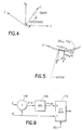
- FIG. 2 A typical transducer array geometry is shown in FIG. 2.
- the elements of the array and the focal points all lie within a single plane in three-dimensional space.
- the geometry in two dimensions x and z , where the x axis is tangential to the center of the array face and the z axis is orthogonal to the x axis.
- the elements in the array are indexed by the letter " i ".
- the position of each i -th element is indicated by its coordinates in x (azimuthal) and z (axial): El x i and El z i , respectively.
- the vector along which the focal points lie may be described by an angle ⁇ , relative to the z axis.
- the position of the focal point, as a function of time, is indicated by coordinates Focx(t) and Focz( t ).
- Some transducer arrays, referred to as 2D arrays have elements out of the x - z plane, in the elevational or y direction.
- D i ( t ) hypot ⁇ hypot[(El x i -Foc x ( t )), (El z i - Foc z ( t ))], (El y i - Foc y ( t )))
- the receive focal point progresses from a point on the array face, along a line through the volume being imaged. This line is called a vector or beam.
- the point on the array face, at the intersection of the vector and the array, is called the vector phase center.
- the distance from the phase center to the focal point is r(t).
- the beamformer delays the signals at each transducer element by a time T i ( t ) to compensate for the differences in propagation times.
- the propagation time is simply the propagation path distance divided by the speed of sound c (approximately 1.54 mm/ ⁇ sec in tissue). Because the focal point is a function of time in reception, the delays are also a function of time. However, the delay at the phase center is kept constant to ensure a linear relationship between the depth of an object along the vector and the output of the corresponding echo signal from the beamformer. In addition, an offset delay is added to ensure the applied beamforming time delays are positive, a requirement to be causal.
- the beamformer must provide apodization weightings or values which control the size and shading of the array active aperture. Apodization is applied according to the projection of the array onto a plane orthogonal to the vector. The apodization value for a particular element is determined by the projected distance from the center of the aperture divided by the projected aperture size. The aperture size and center may be controlled according to desired effective f-numbers and acceptance angles.
- a preferred embodiment of the invention includes a plurality of delay calculators 28 distributed throughout the beamformer.
- Each delay calculator provides beamforming delays and apodization for a plurality of channels (32)/elements (34) via a channel control bus 30.
- the delay calculators are initialized with element position coordinates. Then, while imaging, focal coordinates and steering angles are broadcast to all delay calculators. All parameters may be provided to the delay calculators over a single beamformer control bus 26.
- the delay calculator uses a cordic to perform the aperture projections and carry out the hypot function.
- the cordic provides a very efficient and accurate means of performing the projection and calculating the hypotenuse. It performs successive coordinate transformations, in two dimensions, using coefficients that are simple powers of two. Thus it requires a small number of bit shifts and adds. It is pipelined, allowing high throughput.
- the resulting apodization values and time delays are then provided by a channel control bus 30 to a plurality of channels 32.
- a hypotenuse can be calculated by first taking the absolute value of the coordinates, to put it in the first quadrant, then using the cordic to rotate it onto the x' axis (aligned with the hypotenuse to be calculated) and output the resulting x' value.
- An apodization projection can be performed by simply rotating the coordinate system (see FIG. 5) about the origin by an angle - ⁇ , so that the z ' axis is parallel with the vector.
- the transformed element x coordinates, El x' i then provide the element position in the projection plane.
- the aperture center AC x ' and the inverse aperture iAp are other parameters broadcast to all delay calculators.
- the product of Ap x i ' and the inverse aperture iAp is used to index a window function comprising a table of shading (apodization) values.
- a hypotenuse in three dimensions may be calculated by two successive cordics.
- the first transforms x and z to a rotated coordinate system, x' and z' .
- the second then rotates x' and y to x " and y ".
- the first cordic calculates the hypotenuse in the x-z plane by rotating it onto x', and the second cordic calculates the three-dimensional hypotenuse, now in the x'-y plane, by rotating it onto x ".
- the apodization projection may be provided by first rotating the x and z axes about the y axes, and then rotating the y and x' axes about the z axis.
- the cordic rotates the inputs by an angle corresponding to the N sign bits, s 0 through s N -1 , provided at the input. This is used to project element positions onto a rotated axis for apodization.
- the rotate sign bits may be calculated according to the vector angle ⁇ prior to transmit and broadcast, as AngS, to all delay calculators 28 via the beamformer control bus 32 (see FIG. 3).
- the cordic rotates the coordinates to the x' axis to provide the hypotenuse as x' .
- This is done by setting the sign bit s k at each stage to the sign bit of the input z k .
- the direction of rotation is always toward the x' axis.
- the angle of rotation becomes smaller and the hypotenuse asymptotically approaches the x' axis.
- E max the maximum remaining error
- h max the maximum hypotenuse.
- This invention provides all of the advantages of the prior art with none of the disadvantages. It is agile, simple, and accurate. There are no vector- and element-dependent parameters. Vector-dependent parameters are element independent. Element-dependent parameters are vector independent. The resulting small number of parameters allow for quick reprogramming. In addition, because there is no state machine, delay computation may begin anywhere along the vector. The cordic is inherently pipelined and extremely simple. It requires only a small number of adds/subtracts. Its precision is determined by the number of stages with no underlying approximation.
- the delay calculators 28 receive all the required parameters over a beamformer control bus 26.
- This control bus requires at least 16 data bits, 13 address bits and a "Start" bit.
- the "Start" signal resets the calculators for the beginning of a new vector.
- Transducer array geometry parameters are written before scanning, while vector parameters are written synchronous with scanning. For dynamic reception, this bus should run at 15 MHz. (For dual parallel beam reception, a 30-MHz bus or separate 15-MHz busses are required). Separate, but nearly identical, control structures and busses may be used for transmit and receive.
- the MUX State is required when a multiplexer is used to connect different physical element(s) to individual channels. This is typical for large linear or convex transducers where the number of elements exceeds the number of beamforming channels. The element position corresponding to each delay channel then depends on the MUX State.
- Each delay calculator 28 outputs delay and apodization information to a respective plurality of beamformer channels 32 through a respective channel control bus 30.
- this bus should have 16 data bits, 5 address bits and a "Strt" signal.
- the delay calculator outputs delay and apodization data interleaved by channel. Providing a 2.5 MHz update per channel, for 16 channels, requires a 40-MHz bus. Four address bits index the channels and one address bit indicates delay or apodization.
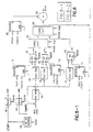
- FIG. 8 A preferred embodiment of the delay calculator is shown in composite FIG. 8 (consisting of FIGS. 8-1 and 8-2).
- This embodiment of the delay calculator provides delay and apodization for 16 channels.
- Four relatively small random access memories (RAMs) are used to store information about the activated array.
- This delay calculator provides 256 possible MUX states with a maximum of four physical elements associated with each channel.
- a "MUX" RAM 64 stores a 2-bit value to indicate which of the four available elements is connected to each channel per MUX state.
- Three “Chn” RAMs 66, 68 and 70 contain the coordinates for each of the four associated physical elements per channel. This two-step structure provides complete flexibility for multiplexer designs without large memories.
- the delay calculator loops through 16 channels at a 40 MHz rate so that delays for all channels may be calculated at the required 2.5 MHz rate. This is done with a 4-bit up counter 58 (see FIG. 8-1), initialized with the "Start” signal.
- the "Start” signal is also received by a delay circuit 60.
- the up counter 58 outputs a 4-bit channel index (labeled “Channel” in FIG. 8) to the "Chn” RAMs 66, 68 and 70 and to another delay circuit 62.
- the delay circuits 60 and 62 respectively output delayed versions of the "Start” and “Channel” signals (labeled “Strt” and “Chn”, respectively, in FIG. 8-1).
- the "Strt” and “Chn” signals are output aligned with the corresponding delay and apodization data.
- the 4-bit channel index is combined with an 8-bit MUX State signal to look up the element index from the "MUX" RAM 64.
- the resulting two-bit element index is combined with the 4-bit channel index to look up the physical element coordinates in the "Chn" RAMs 66, 68 and 70.
- the "Start” signal triggers a brief initialization, followed by the pipelined delay and apodization calculation.
- the initialization provides for setup of the "MUX” RAM 64 and an element projection (“PROJ”) RAM 92 (see FIG. 8-2).
- the first loop through the 16 channels is used to setup the element projection RAM 92 for apodization.
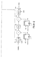
- the element positions from "Chn" RAMs 66, 68 and 70 are passed directly to the cordics via line B and multiplexer 110 (see FIG. 9) of the respective ALUs 78, 80 and 82, and the controls for the cordics 84 and 86 are set to perform a fixed-angle rotation according to AngS.
- the results are stored in the projection RAM 92.
- a second loop through the 16 channels may be used to prepare the pipes for dynamic calculations.
- the total initialization time is less than 0.5 ⁇ sec. Synchronizing the cordic controls with the pipeline can eliminate the need for the extra loop, reducing initialization to 0.25 ⁇ sec.
- the delay calculator After initialization the delay calculator begins updating the dynamic parameters and producing dynamic delays and apodization.
- the focus coordinates from registers 72 and 74 are respectively subtracted in ALUs 78 and 80 from the element coordinates from "ChnX” RAM 66 and “ChnZ” RAM 68 and the absolute values of the coordinate differences x and z are fed to cordic 84, and the focus coordinates from register 76 are subtracted in ALU 82 from the element coordinates from "ChnY” RAM 70 and the absolute value of the difference y is fed to cordic 88, along with the output of cordic 84.
- These operations performed by each ALU are depicted in FIG. 9 by adder/subtractor 106 and absolute value block 108.
- the adder/subtracter 106 receives the focus coordinate via line A and the element position coordinate via line B.
- the multiplexer 110 is switched to pass the absolute value to the respective cordic.
- the first cordic 84 transforms x and z to a rotated coordinate system, x ' and z '.
- the second cordic 86 then rotates x' and y to x " and y ".
- the first cordic 84 calculates the hypotenuse in the x-z plane by rotating it onto x', and the second cordic 86 calculates the three-dimensional hypotenuse, now in the x'-y plane, by rotating it onto x ".
- the calculated hypotenuse corresponds to the propagation time.
- the range offset time ( R offset ) from register 88 is subtracted from the output of cordic 86 in adder 90 to produce the delay.
- the aperture center (Apx') from register 94 is subtracted in adder 96 from the element positions read from the projection RAM 92, in accordance with Eq. (7).
- the absolute value (block 98) of the resulting distance Ap x i ' is multiplied by the inverse aperture size (iAP) from register 100 by multiplier 102.
- the resulting product is used to index a window function table in "window" RAM 104, which produces an 8-bit shading (i.e., apodization) value.
- the "window" RAM 104 preferably stores a bank of window function tables, with one table be selected by the input "BANK".
- the focus and element coordinates should all be expressed in 6.25 nsec units, pre-scaled by 1/ M . Providing additional fractional bits can help maintain precision.
- the R offset is not prescaled by 1/ M since it is after the cordics.
Landscapes
- Engineering & Computer Science (AREA)
- Physics & Mathematics (AREA)
- General Physics & Mathematics (AREA)
- Radar, Positioning & Navigation (AREA)
- Theoretical Computer Science (AREA)
- Remote Sensing (AREA)
- Mathematical Analysis (AREA)
- Acoustics & Sound (AREA)
- Computational Mathematics (AREA)
- Pure & Applied Mathematics (AREA)
- Computing Systems (AREA)
- Computer Networks & Wireless Communication (AREA)
- Mathematical Optimization (AREA)
- General Engineering & Computer Science (AREA)
- Multimedia (AREA)
- Measurement Of Velocity Or Position Using Acoustic Or Ultrasonic Waves (AREA)
- Ultra Sonic Daignosis Equipment (AREA)
- Investigating Or Analyzing Materials By The Use Of Ultrasonic Waves (AREA)
- Image Processing (AREA)
- Closed-Circuit Television Systems (AREA)
- Transducers For Ultrasonic Waves (AREA)
Claims (18)
- Système de formation de faisceau comprenant :un réseau de transducteurs (2) comprenant une multitude d'éléments transducteurs (34) agencés dans un plan ayant des axes de coordonnées x et z ; etun dispositif de formation de faisceau comprenant une multitude de canaux de réception respectivement couplés fonctionnellement à ladite multitude d'éléments transducteurs (34), caractérisé par une première mémoire (72, 74) stockant des coordonnées x et z d'une position focale, une deuxième mémoire (66, 68) stockant des ensembles respectifs de coordonnées de positions respectives de ladite multitude d'éléments transducteurs (34), chaque ensemble de coordonnées comprenant une coordonnée x et une coordonnée z, un premier circuit d'addition/soustraction (78) connecté auxdites première et deuxième mémoires pour former des différences de coordonnées x respectives entre ladite coordonnée x de ladite position focale et les coordonnées x respectives desdites positions d'éléments, un deuxième circuit d'addition/soustraction (80) connecté auxdites première et deuxième mémoires pour former des différences de coordonnées z respectives entre ladite coordonnée z de ladite position focale et les coordonnées z respectives desdites positions d'éléments, un rotateur de type cordic (84) connecté auxdits premier et deuxième circuits d'addition/soustraction (78, 80) pour effectuer des transformations de coordonnées des sorties desdits premier et deuxième circuits d'addition/soustraction (78, 80) et calculer de ce fait des hypoténuses respectives représentant les distances de ladite position focale auxdits éléments transducteurs respectifs (34), et un générateur de retard (28) pour appliquer des retards respectifs à des canaux de réception respectifs, chaque retard étant fonction d'une sortie d'hypoténuse respective dudit rotateur de type cordic (84).
- Système de formation de faisceau selon la revendication 1, dans lequel ledit rotateur de type cordic (84) calcule une hypoténuse respective en fonction de différences de coordonnées x et z respectives et de bits de signe respectif de coordonnées en z respectives lorsque ledit rotateur cordic est dans un premier état.
- Système de formation de faisceau selon la revendication 1, dans lequel ledit rotateur cordic réalise une projection d'apodisation respective en fonction de positions d'éléments x et z respectives et de bits de signe de rotation respectifs qui sont fonction d'un angle de vecteur lorsque ledit rotateur cordic est dans un deuxième état.
- Système de formation de faisceau selon la revendication 2, dans lequel ledit générateur de retard applique des retards qui sont fonction d'hypoténuses respectives et d'un décalage de gamme.
- Système de formation de faisceau selon la revendication 3, comprenant en outre un générateur de valeurs d'apodisation pour appliquer des valeurs d'apodisation respectives à des canaux de réception respectifs, chaque valeur d'apodisation étant fonction d'une projection d'apodisation respective, d'un centre d'ouverture et d'une taille d'ouverture inverse.
- Système de formation de faisceau selon la revendication 5, dans lequel ledit générateur de valeurs d'apodisation comprend une troisième mémoire (104) stockant au moins une table de fonction de fenêtre.
- Système de formation de faisceau selon la revendication 1, comprenant en outre un compteur pour lire successivement lesdits ensembles respectifs de coordonnées de position d'élément x et z dans ladite deuxième mémoire.
- Système de formation de faisceau selon la revendication 1, dans lequel ledit rotateur cordic comprend une pluralité d'étages successifs (36), chaque étage effectuant une transformation de coordonnées qui exécute une rotation des entrées de cet étage, l'angle de rotation devenant plus petit pour chaque étage successif.
- Système de formation de faisceau selon la revendication 8, dans lequel le nombre d'étages dudit rotateur cordic est N, et pour un indice d'étage k = 0 à N-1, chaque étage exécute la transformation de coordonnées suivante :où sk = ±1.

- Système de formation de faisceau selon la revendication 1, comprenant en outre un multiplexeur comprenant une multitude d'interrupteurs de multiplexage ayant des états de commutation déterminés par un état MUX, dans lequel ledit dispositif de formation de faisceau comprend en outre une troisième mémoire pour mémoriser ledit état MUX, ladite deuxième mémoire ayant des entrées couplées de manière fonctionnelle à des sorties de ladite troisième mémoire.
- Système d'imagerie comprenant :caractérisé en ce que ledit premier calculateur de retard (28) comprend un premier rotateur de type cordic (84) pour calculer des hypoténuses respectives représentant les distances de ladite position focale auxdits éléments transducteurs respectifs (34) dans un premier état de rotateur cordic, et un premier générateur de retard pour délivrer ledit premier ensemble de retards de réception respectifs audit premier bus de commande de canaux (30), chaque retard de réception dudit premier ensemble étant fonction d'une hypoténuse respective délivrée par ledit premier rotateur cordic (84).un réseau de transducteurs (2) comprenant une multitude d'éléments transducteurs (34) agencés dans un plan ayant des axes de coordonnées x et z ;un premier calculateur de retard (28) pour calculer un premier ensemble de retards de réception respectifs en fonction d'une position focale et de positions respectives d'un premier ensemble desdits éléments transducteurs ;un dispositif de formation de faisceau d'émission (8) programmé pour activer ledit réseau de transducteurs pour émettre un faisceau d'ultrasons focalisé ;un dispositif de formation de faisceau de réception (10) comprenant un premier ensemble de canaux de réception (32) pour convertir des signaux analogiques respectifs provenant dudit premier ensemble d'éléments transducteurs (34) en vecteurs respectifs d'échantillons numériques, un premier bus de commande de canaux (30) pour appliquer ledit premier ensemble de retards de réception respectifs auxdits vecteurs respectifs d'échantillons numériques dudit premier ensemble de canaux de réception (32), et un dispositif d'addition de faisceaux pour additionner au moins lesdits vecteurs retardés d'échantillons numériques dudit premier ensemble de canaux de réception (32) pour produire un signal de réception net ;un processeur (16) pour créer un signal d'image à partir dudit signal de réception net ; etun dispositif d'affichage (22) pour afficher une image ayant une partie d'image qui est fonction dudit signal d'image,
- Système d'imagerie selon la revendication 11, comprenant en outre un deuxième calculateur de retard (28) pour calculer un deuxième ensemble de retards de réception respectifs en fonction de ladite position focale et de positions respectives d'un deuxième ensemble desdits éléments transducteurs (34), dans lequel ledit dispositif de formation de faisceau de réception comprend en outre un deuxième ensemble de canaux de réception (32) pour convertir des signaux analogiques respectifs provenant dudit deuxième ensemble d'éléments transducteurs en vecteurs respectifs d'échantillons numériques, et un deuxième bus de commande de canaux (30) pour appliquer ledit deuxième ensemble de retards de réception respectifs auxdits vecteurs respectifs d'échantillons numériques dudit deuxième ensemble de canaux de réception (32), et ledit deuxième calculateur de retard (28) comprend un deuxième rotateur cordic (84) pour calculer des hypoténuses respectives en fonction de ladite position focale et desdites positions respectives dudit deuxième ensemble d'éléments transducteurs (34), et un deuxième générateur de retards pour délivrer ledit deuxième ensemble de retards de réception respectifs audit deuxième bus de commande de canaux (30), chaque retard de réception dudit deuxième ensemble étant fonction d'une hypoténuse respective délivrée par ledit deuxième rotateur cordic (84).
- Système d'imagerie selon la revendication 12, comprenant en outre un ordinateur pour générer un ensemble de paramètres de vecteurs, et un bus de commande (26) de dispositif de formation de faisceau pour distribuer ledit ensemble de paramètres de vecteurs auxdits premier et deuxième calculateurs de retard (28), lesdits premier et deuxième ensembles de retards de réception étant fonction desdits paramètres de vecteurs.
- Système d'imagerie selon la revendication 11, dans lequel ledit premier rotateur cordic effectue des projections d'apodisation respectives en fonction de ladite position focale et desdites positions respectives dudit premier ensemble d'éléments transducteurs dans un deuxième état de rotateur cordic, et ledit premier calculateur de retard comprend en outre un générateur de valeurs d'apodisation pour appliquer des valeurs d'apodisation de réception respectives audit premier ensemble de canaux de réception respectifs, chaque valeur d'apodisation de réception étant fonction d'une projection d'apodisation respective.
- Procédé de formation de faisceaux d'ultrasons, comprenant les étapes consistant à ;caractérisé par les étapes consistant à :mémoriser des paramètres géométriques d'un réseau de transducteurs (2) comportant une multitude d'éléments transducteurs (34) ;mémoriser des paramètres de vecteurs pour former un faisceau focalisé ayant une position focale ;calculer des hypoténuses respectives représentant les distances de ladite position focale auxdits éléments transducteurs respectifs (34) en fonction desdits paramètres géométriques et desdits paramètres de vecteurs en utilisant plusieurs étages de rotation cordic pour obtenir chaque hypoténuse ; etgénérer des retards respectifs en fonction desdites hypoténuses calculées, et former un faisceau en utilisant lesdits retards respectifs.
- Procédé selon la revendication 15, comprenant en outre les étapes consistant à :effectuer des projections d'apodisation respectives pour lesdits éléments transducteurs respectifs (34) en fonction desdits paramètres géométriques et desdits paramètres de vecteurs en utilisant plusieurs étages de rotation cordic pour effectuer chaque projection ; etgénérer des valeurs d'ombrage respectives en fonction desdites projections d'apodisation respectives, et utiliser lesdites valeurs d'ombrage respectives au cours de la formation dudit faisceau.
- Procédé selon la revendication 15, dans lequel chaque étage de rotation cordic comprend des décalages binaires et des additions.
- Procédé selon la revendication 15, dans lequel chaque étage de rotation cordic comprend une transformation de coordonnées utilisant des coefficients qui sont des puissances de deux.
Applications Claiming Priority (3)
| Application Number | Priority Date | Filing Date | Title |
|---|---|---|---|
| US09/223,950 US6123671A (en) | 1998-12-31 | 1998-12-31 | Method and apparatus for distributed, agile calculation of beamforming time delays and apodization values |
| US223950 | 1998-12-31 | ||
| PCT/US1999/028652 WO2000041162A1 (fr) | 1998-12-31 | 1999-12-06 | Procede et dispositif de calcul agile reparti pour des retards dans la formation de rayons et valeurs d'apodisation |
Publications (2)
| Publication Number | Publication Date |
|---|---|
| EP1060470A1 EP1060470A1 (fr) | 2000-12-20 |
| EP1060470B1 true EP1060470B1 (fr) | 2005-12-21 |
Family
ID=22838671
Family Applications (1)
| Application Number | Title | Priority Date | Filing Date |
|---|---|---|---|
| EP99961927A Expired - Lifetime EP1060470B1 (fr) | 1998-12-31 | 1999-12-06 | Procede et dispositif de calcul agile reparti pour des retards dans la formation de rayons et valeurs d'apodisation |
Country Status (5)
| Country | Link |
|---|---|
| US (1) | US6123671A (fr) |
| EP (1) | EP1060470B1 (fr) |
| JP (1) | JP4428477B2 (fr) |
| DE (1) | DE69929038T2 (fr) |
| WO (1) | WO2000041162A1 (fr) |
Families Citing this family (26)
| Publication number | Priority date | Publication date | Assignee | Title |
|---|---|---|---|---|
| JP3537358B2 (ja) * | 1999-08-30 | 2004-06-14 | 松下電器産業株式会社 | 超音波診断装置 |
| JP3306403B2 (ja) * | 2000-01-19 | 2002-07-24 | 松下電器産業株式会社 | 超音波診断装置 |
| US6592524B2 (en) * | 2000-12-22 | 2003-07-15 | Siemens Medical Solutions Usa, Inc. | Transmit beamformer delay architecture and method for diagnostic medical ultrasound |
| US6443897B1 (en) | 2000-12-28 | 2002-09-03 | Ge Medical Systems Global Technology Company, Llc | Refraction delay error correction using agile beamformer |
| US7024169B2 (en) * | 2002-01-25 | 2006-04-04 | Qualcomm Incorporated | AMPS receiver using a zero-IF architecture |
| JP4195276B2 (ja) * | 2002-11-27 | 2008-12-10 | 古野電気株式会社 | 超音波送信装置、超音波送受信装置およびソナー装置 |
| US7148836B2 (en) | 2004-03-05 | 2006-12-12 | The Regents Of The University Of California | Obstacle penetrating dynamic radar imaging system |
| CN101097256B (zh) * | 2006-06-28 | 2011-03-23 | 深圳迈瑞生物医疗电子股份有限公司 | 超声波束合成聚焦参数实时计算方法及装置 |
| CN101112320B (zh) * | 2006-07-28 | 2010-07-21 | 深圳迈瑞生物医疗电子股份有限公司 | 波束合成的接收聚焦参数的实时计算方法及其装置 |
| CN101116622B (zh) * | 2006-08-02 | 2010-12-01 | 深圳迈瑞生物医疗电子股份有限公司 | 波束合成的接收变迹参数的实时计算方法及其装置 |
| CN101373181B (zh) * | 2007-08-24 | 2012-03-21 | 深圳迈瑞生物医疗电子股份有限公司 | 实时计算逐点变迹系数的方法及装置 |
| CN101422377B (zh) * | 2007-10-31 | 2012-03-28 | 深圳迈瑞生物医疗电子股份有限公司 | 多焦点数据的接收处理方法 |
| JP5645421B2 (ja) * | 2010-02-23 | 2014-12-24 | キヤノン株式会社 | 超音波画像装置および遅延制御方法 |
| CN101858972B (zh) * | 2010-03-23 | 2013-01-30 | 深圳市蓝韵实业有限公司 | 基于延时参数实时计算和流水线的多波束合成方法和装置 |
| CN102768358B (zh) * | 2011-05-05 | 2014-03-26 | 中国科学院声学研究所 | 一种基于fpga的水下实时成像方法及系统 |
| CN102508230A (zh) * | 2011-10-20 | 2012-06-20 | 哈尔滨工程大学 | 图像声纳中时延、相移波束形成的fpga实现方法 |
| JP6188393B2 (ja) * | 2012-11-30 | 2017-08-30 | 東芝メディカルシステムズ株式会社 | 超音波診断装置及び制御プログラム |
| JP6301063B2 (ja) * | 2013-03-18 | 2018-03-28 | キヤノンメディカルシステムズ株式会社 | 超音波診断装置及び制御プログラム |
| US10613205B2 (en) | 2014-10-06 | 2020-04-07 | Analog Devices, Inc. | Systems and methods for ultrasound beamforming |
| US10405829B2 (en) | 2014-12-01 | 2019-09-10 | Clarius Mobile Health Corp. | Ultrasound machine having scalable receive beamformer architecture comprising multiple beamformers with common coefficient generator and related methods |
| CN105629250A (zh) * | 2016-03-31 | 2016-06-01 | 芜湖应天光电科技有限责任公司 | 一种水下三维场景实时成像系统 |
| JP6772944B2 (ja) | 2017-04-19 | 2020-10-21 | トヨタ自動車株式会社 | 自動運転システム |
| CN110333490B (zh) * | 2019-07-30 | 2022-12-27 | 西安电子工程研究所 | 基于流水线工作模式的异步多通道任意波形产生方法 |
| CN110693524B (zh) * | 2019-10-16 | 2022-08-05 | 深圳蓝影医学科技股份有限公司 | 一种超声医学成像聚焦校正方法和装置 |
| CN113552573B (zh) * | 2021-06-29 | 2022-07-29 | 复旦大学 | 一种基于超声环阵合成孔径接收的快速成像算法 |
| WO2023191790A1 (fr) * | 2022-03-31 | 2023-10-05 | Exo Imaging, Inc. | Systèmes et procédés d'échographie avec des micro-formeurs de faisceaux dynamiques |
Family Cites Families (6)
| Publication number | Priority date | Publication date | Assignee | Title |
|---|---|---|---|---|
| US4896287A (en) * | 1988-05-31 | 1990-01-23 | General Electric Company | Cordic complex multiplier |
| EP0365226A3 (fr) * | 1988-10-17 | 1991-02-20 | Raytheon Company | Méthode et dispositif "CORDIC" pour approximer l'amplitude et la phase d'un nombre complexe |
| US4983970A (en) * | 1990-03-28 | 1991-01-08 | General Electric Company | Method and apparatus for digital phased array imaging |
| US5501219A (en) * | 1993-09-30 | 1996-03-26 | Siemens Medical Systems, Inc. | Real-time dynamic time-of-flight calculator |
| US5488588A (en) * | 1994-09-07 | 1996-01-30 | General Electric Company | Ultrasonic imager having wide-bandwidth dynamic focusing |
| US5653236A (en) * | 1995-12-29 | 1997-08-05 | General Electric Company | Apparatus for real-time distributed computation of beamforming delays in ultrasound imaging system |
-
1998
- 1998-12-31 US US09/223,950 patent/US6123671A/en not_active Expired - Lifetime
-
1999
- 1999-12-06 EP EP99961927A patent/EP1060470B1/fr not_active Expired - Lifetime
- 1999-12-06 DE DE69929038T patent/DE69929038T2/de not_active Expired - Lifetime
- 1999-12-06 WO PCT/US1999/028652 patent/WO2000041162A1/fr not_active Ceased
- 1999-12-06 JP JP2000592816A patent/JP4428477B2/ja not_active Expired - Lifetime
Also Published As
| Publication number | Publication date |
|---|---|
| DE69929038D1 (de) | 2006-01-26 |
| WO2000041162A1 (fr) | 2000-07-13 |
| EP1060470A1 (fr) | 2000-12-20 |
| US6123671A (en) | 2000-09-26 |
| JP4428477B2 (ja) | 2010-03-10 |
| JP2002534192A (ja) | 2002-10-15 |
| DE69929038T2 (de) | 2006-08-24 |
Similar Documents
| Publication | Publication Date | Title |
|---|---|---|
| EP1060470B1 (fr) | Procede et dispositif de calcul agile reparti pour des retards dans la formation de rayons et valeurs d'apodisation | |
| EP0161587B1 (fr) | Système d'imagerie acoustique à réseau de transducteurs à commande par déphasage | |
| US6443897B1 (en) | Refraction delay error correction using agile beamformer | |
| US5653236A (en) | Apparatus for real-time distributed computation of beamforming delays in ultrasound imaging system | |
| US4471785A (en) | Ultrasonic imaging system with correction for velocity inhomogeneity and multipath interference using an ultrasonic imaging array | |
| US5409007A (en) | Filter to reduce speckle artifact in ultrasound imaging | |
| AU743355B2 (en) | Multi-dimensional beamforming device | |
| EP0916966B1 (fr) | Procédé de focalisation d'un signal ultrasonsore et appareil pour système d'imagerie par ultrasons | |
| EP0642036B1 (fr) | Appareil diagnostic à ultrasons | |
| JPH0870404A (ja) | 超音波ビーム形成装置における遅延生成装置 | |
| US7804736B2 (en) | Delay controller for ultrasound receive beamformer | |
| US5415173A (en) | Ultrasound diagnosis system | |
| JP2022502113A (ja) | 高い表示フレームレートで幅広集束送信ビームを用いる3d超音波イメージング | |
| EP0179073B1 (fr) | Systeme de mise en image ultrasonique hybride de non-invasion | |
| US11911218B2 (en) | Two dimensional ultrasonic array transducer with one dimensional patches | |
| US6423004B1 (en) | Real-time ultrasound spatial compounding using multiple angles of view | |
| US11199625B2 (en) | Rapid synthetic focus ultrasonic imaging with large linear arrays | |
| JPH078492A (ja) | 超音波診断装置 | |
| JPH07116162A (ja) | 超音波計測装置およびその送受信位相補正方法 | |
| US4320660A (en) | Fresnel focussed imaging system | |
| US4228686A (en) | Fresnel focussed imaging system | |
| JP2001104307A (ja) | 柔軟性のある受信ビームフォーミング用集積回路アーキテクチャ | |
| JP2000116652A (ja) | 超音波撮像方法および装置 | |
| AU9715301A (en) | Multi-dimensional beamforming device | |
| JPH0320715B2 (fr) |
Legal Events
| Date | Code | Title | Description |
|---|---|---|---|
| PUAI | Public reference made under article 153(3) epc to a published international application that has entered the european phase |
Free format text: ORIGINAL CODE: 0009012 |
|
| AK | Designated contracting states |
Kind code of ref document: A1 Designated state(s): AT BE CH CY DE DK ES FI FR GB GR IE IT LI LU MC NL PT SE |
|
| 17P | Request for examination filed |
Effective date: 20010115 |
|
| 17Q | First examination report despatched |
Effective date: 20030526 |
|
| RBV | Designated contracting states (corrected) |
Designated state(s): DE NL |
|
| GRAP | Despatch of communication of intention to grant a patent |
Free format text: ORIGINAL CODE: EPIDOSNIGR1 |
|
| GRAS | Grant fee paid |
Free format text: ORIGINAL CODE: EPIDOSNIGR3 |
|
| GRAA | (expected) grant |
Free format text: ORIGINAL CODE: 0009210 |
|
| AK | Designated contracting states |
Kind code of ref document: B1 Designated state(s): DE NL |
|
| REF | Corresponds to: |
Ref document number: 69929038 Country of ref document: DE Date of ref document: 20060126 Kind code of ref document: P |
|
| PLBE | No opposition filed within time limit |
Free format text: ORIGINAL CODE: 0009261 |
|
| STAA | Information on the status of an ep patent application or granted ep patent |
Free format text: STATUS: NO OPPOSITION FILED WITHIN TIME LIMIT |
|
| 26N | No opposition filed |
Effective date: 20060922 |
|
| PGFP | Annual fee paid to national office [announced via postgrant information from national office to epo] |
Ref country code: NL Payment date: 20071223 Year of fee payment: 9 |
|
| NLV4 | Nl: lapsed or anulled due to non-payment of the annual fee |
Effective date: 20090701 |
|
| PG25 | Lapsed in a contracting state [announced via postgrant information from national office to epo] |
Ref country code: NL Free format text: LAPSE BECAUSE OF NON-PAYMENT OF DUE FEES Effective date: 20090701 |
|
| PGFP | Annual fee paid to national office [announced via postgrant information from national office to epo] |
Ref country code: DE Payment date: 20111229 Year of fee payment: 13 |
|
| PG25 | Lapsed in a contracting state [announced via postgrant information from national office to epo] |
Ref country code: DE Free format text: LAPSE BECAUSE OF NON-PAYMENT OF DUE FEES Effective date: 20130702 |
|
| REG | Reference to a national code |
Ref country code: DE Ref legal event code: R119 Ref document number: 69929038 Country of ref document: DE Effective date: 20130702 |