EP1060909B1 - Fototräger und Album - Google Patents
Fototräger und Album Download PDFInfo
- Publication number
- EP1060909B1 EP1060909B1 EP00201964A EP00201964A EP1060909B1 EP 1060909 B1 EP1060909 B1 EP 1060909B1 EP 00201964 A EP00201964 A EP 00201964A EP 00201964 A EP00201964 A EP 00201964A EP 1060909 B1 EP1060909 B1 EP 1060909B1
- Authority
- EP
- European Patent Office
- Prior art keywords
- ink
- butyl
- pockets
- dye
- transparent
- Prior art date
- Legal status (The legal status is an assumption and is not a legal conclusion. Google has not performed a legal analysis and makes no representation as to the accuracy of the status listed.)
- Expired - Lifetime
Links
- 230000027455 binding Effects 0.000 claims description 15
- 238000009739 binding Methods 0.000 claims description 15
- 238000001035 drying Methods 0.000 claims description 9
- 230000005855 radiation Effects 0.000 claims description 7
- 230000000712 assembly Effects 0.000 claims description 3
- 238000000429 assembly Methods 0.000 claims description 3
- 230000000717 retained effect Effects 0.000 claims description 2
- 239000000463 material Substances 0.000 description 115
- 239000000976 ink Substances 0.000 description 104
- 125000000999 tert-butyl group Chemical group [H]C([H])([H])C(*)(C([H])([H])[H])C([H])([H])[H] 0.000 description 94
- 239000000975 dye Substances 0.000 description 73
- 239000010410 layer Substances 0.000 description 56
- -1 pyrrlyl Chemical group 0.000 description 25
- 125000003118 aryl group Chemical group 0.000 description 19
- 239000000203 mixture Substances 0.000 description 19
- 238000000034 method Methods 0.000 description 18
- 238000009472 formulation Methods 0.000 description 16
- 150000001875 compounds Chemical class 0.000 description 15
- 238000007639 printing Methods 0.000 description 15
- 230000000153 supplemental effect Effects 0.000 description 14
- 238000012546 transfer Methods 0.000 description 13
- 125000004429 atom Chemical group 0.000 description 11
- 125000001072 heteroaryl group Chemical group 0.000 description 11
- 239000000243 solution Substances 0.000 description 11
- 125000000217 alkyl group Chemical group 0.000 description 10
- PEDCQBHIVMGVHV-UHFFFAOYSA-N Glycerine Chemical compound OCC(O)CO PEDCQBHIVMGVHV-UHFFFAOYSA-N 0.000 description 9
- MTHSVFCYNBDYFN-UHFFFAOYSA-N diethylene glycol Chemical compound OCCOCCO MTHSVFCYNBDYFN-UHFFFAOYSA-N 0.000 description 9
- 229910052751 metal Inorganic materials 0.000 description 9
- 239000002184 metal Substances 0.000 description 9
- 238000001228 spectrum Methods 0.000 description 9
- 125000001997 phenyl group Chemical group [H]C1=C([H])C([H])=C(*)C([H])=C1[H] 0.000 description 8
- 239000011230 binding agent Substances 0.000 description 7
- 238000004020 luminiscence type Methods 0.000 description 7
- 239000011701 zinc Substances 0.000 description 7
- IJGRMHOSHXDMSA-UHFFFAOYSA-N Atomic nitrogen Chemical compound N#N IJGRMHOSHXDMSA-UHFFFAOYSA-N 0.000 description 6
- 238000006243 chemical reaction Methods 0.000 description 6
- 125000001624 naphthyl group Chemical group 0.000 description 6
- 230000003287 optical effect Effects 0.000 description 6
- 238000010521 absorption reaction Methods 0.000 description 5
- 238000003384 imaging method Methods 0.000 description 5
- 239000003446 ligand Substances 0.000 description 5
- 230000036961 partial effect Effects 0.000 description 5
- 229920000642 polymer Polymers 0.000 description 5
- 239000000126 substance Substances 0.000 description 5
- 125000001424 substituent group Chemical group 0.000 description 5
- XLYOFNOQVPJJNP-UHFFFAOYSA-N water Substances O XLYOFNOQVPJJNP-UHFFFAOYSA-N 0.000 description 5
- SMWDFEZZVXVKRB-UHFFFAOYSA-N Quinoline Chemical compound N1=CC=CC2=CC=CC=C21 SMWDFEZZVXVKRB-UHFFFAOYSA-N 0.000 description 4
- 229920002301 cellulose acetate Polymers 0.000 description 4
- 239000007850 fluorescent dye Substances 0.000 description 4
- 229910052736 halogen Inorganic materials 0.000 description 4
- 150000002367 halogens Chemical class 0.000 description 4
- 125000004435 hydrogen atom Chemical class [H]* 0.000 description 4
- 230000003993 interaction Effects 0.000 description 4
- 230000001050 lubricating effect Effects 0.000 description 4
- 125000002496 methyl group Chemical group [H]C([H])([H])* 0.000 description 4
- 230000004048 modification Effects 0.000 description 4
- 238000012986 modification Methods 0.000 description 4
- 229910052757 nitrogen Inorganic materials 0.000 description 4
- 229910052760 oxygen Inorganic materials 0.000 description 4
- 125000002924 primary amino group Chemical group [H]N([H])* 0.000 description 4
- 230000008569 process Effects 0.000 description 4
- 230000002441 reversible effect Effects 0.000 description 4
- 229920006395 saturated elastomer Polymers 0.000 description 4
- 125000000547 substituted alkyl group Chemical group 0.000 description 4
- 239000004094 surface-active agent Substances 0.000 description 4
- 125000000391 vinyl group Chemical group [H]C([*])=C([H])[H] 0.000 description 4
- 229920002554 vinyl polymer Polymers 0.000 description 4
- BCMCBBGGLRIHSE-UHFFFAOYSA-N 1,3-benzoxazole Chemical compound C1=CC=C2OC=NC2=C1 BCMCBBGGLRIHSE-UHFFFAOYSA-N 0.000 description 3
- NECRQCBKTGZNMH-UHFFFAOYSA-N 3,5-dimethylhex-1-yn-3-ol Chemical compound CC(C)CC(C)(O)C#C NECRQCBKTGZNMH-UHFFFAOYSA-N 0.000 description 3
- IHXWECHPYNPJRR-UHFFFAOYSA-N 3-hydroxycyclobut-2-en-1-one Chemical compound OC1=CC(=O)C1 IHXWECHPYNPJRR-UHFFFAOYSA-N 0.000 description 3
- ROFVEXUMMXZLPA-UHFFFAOYSA-N Bipyridyl Chemical group N1=CC=CC=C1C1=CC=CC=N1 ROFVEXUMMXZLPA-UHFFFAOYSA-N 0.000 description 3
- OKTJSMMVPCPJKN-UHFFFAOYSA-N Carbon Chemical compound [C] OKTJSMMVPCPJKN-UHFFFAOYSA-N 0.000 description 3
- 229920008347 Cellulose acetate propionate Polymers 0.000 description 3
- LRHPLDYGYMQRHN-UHFFFAOYSA-N N-Butanol Chemical compound CCCCO LRHPLDYGYMQRHN-UHFFFAOYSA-N 0.000 description 3
- 230000004913 activation Effects 0.000 description 3
- 125000002252 acyl group Chemical group 0.000 description 3
- 239000000853 adhesive Substances 0.000 description 3
- 230000001070 adhesive effect Effects 0.000 description 3
- 230000002776 aggregation Effects 0.000 description 3
- 238000004220 aggregation Methods 0.000 description 3
- 238000013459 approach Methods 0.000 description 3
- 239000011324 bead Substances 0.000 description 3
- ZYGHJZDHTFUPRJ-UHFFFAOYSA-N benzo-alpha-pyrone Natural products C1=CC=C2OC(=O)C=CC2=C1 ZYGHJZDHTFUPRJ-UHFFFAOYSA-N 0.000 description 3
- 229910052799 carbon Inorganic materials 0.000 description 3
- 229920002678 cellulose Polymers 0.000 description 3
- 239000003086 colorant Substances 0.000 description 3
- 238000010668 complexation reaction Methods 0.000 description 3
- 230000006870 function Effects 0.000 description 3
- 238000005286 illumination Methods 0.000 description 3
- 230000007246 mechanism Effects 0.000 description 3
- 238000006384 oligomerization reaction Methods 0.000 description 3
- 239000007800 oxidant agent Substances 0.000 description 3
- 230000001590 oxidative effect Effects 0.000 description 3
- 239000000049 pigment Substances 0.000 description 3
- 238000006116 polymerization reaction Methods 0.000 description 3
- BDERNNFJNOPAEC-UHFFFAOYSA-N propan-1-ol Chemical compound CCCO BDERNNFJNOPAEC-UHFFFAOYSA-N 0.000 description 3
- YKYONYBAUNKHLG-UHFFFAOYSA-N propyl acetate Chemical compound CCCOC(C)=O YKYONYBAUNKHLG-UHFFFAOYSA-N 0.000 description 3
- 239000007787 solid Substances 0.000 description 3
- 238000006467 substitution reaction Methods 0.000 description 3
- 238000012360 testing method Methods 0.000 description 3
- QGKMIGUHVLGJBR-UHFFFAOYSA-M (4z)-1-(3-methylbutyl)-4-[[1-(3-methylbutyl)quinolin-1-ium-4-yl]methylidene]quinoline;iodide Chemical compound [I-].C12=CC=CC=C2N(CCC(C)C)C=CC1=CC1=CC=[N+](CCC(C)C)C2=CC=CC=C12 QGKMIGUHVLGJBR-UHFFFAOYSA-M 0.000 description 2
- RTZKZFJDLAIYFH-UHFFFAOYSA-N Diethyl ether Chemical compound CCOCC RTZKZFJDLAIYFH-UHFFFAOYSA-N 0.000 description 2
- SIKJAQJRHWYJAI-UHFFFAOYSA-N Indole Chemical compound C1=CC=C2NC=CC2=C1 SIKJAQJRHWYJAI-UHFFFAOYSA-N 0.000 description 2
- YNAVUWVOSKDBBP-UHFFFAOYSA-N Morpholine Chemical compound C1COCCN1 YNAVUWVOSKDBBP-UHFFFAOYSA-N 0.000 description 2
- KAESVJOAVNADME-UHFFFAOYSA-N Pyrrole Chemical compound C=1C=CNC=1 KAESVJOAVNADME-UHFFFAOYSA-N 0.000 description 2
- 230000008901 benefit Effects 0.000 description 2
- YHWCPXVTRSHPNY-UHFFFAOYSA-N butan-1-olate;titanium(4+) Chemical compound [Ti+4].CCCC[O-].CCCC[O-].CCCC[O-].CCCC[O-] YHWCPXVTRSHPNY-UHFFFAOYSA-N 0.000 description 2
- 150000001768 cations Chemical class 0.000 description 2
- 229920006217 cellulose acetate butyrate Polymers 0.000 description 2
- 239000003795 chemical substances by application Substances 0.000 description 2
- 229910052801 chlorine Inorganic materials 0.000 description 2
- 239000011248 coating agent Substances 0.000 description 2
- 238000000576 coating method Methods 0.000 description 2
- 235000001671 coumarin Nutrition 0.000 description 2
- 230000006378 damage Effects 0.000 description 2
- 238000005516 engineering process Methods 0.000 description 2
- 125000001495 ethyl group Chemical group [H]C([H])([H])C([H])([H])* 0.000 description 2
- 125000000524 functional group Chemical group 0.000 description 2
- 125000002541 furyl group Chemical group 0.000 description 2
- 229910052739 hydrogen Inorganic materials 0.000 description 2
- 239000001257 hydrogen Substances 0.000 description 2
- 238000007641 inkjet printing Methods 0.000 description 2
- 229910052740 iodine Inorganic materials 0.000 description 2
- 229910052747 lanthanoid Inorganic materials 0.000 description 2
- 150000002602 lanthanoids Chemical class 0.000 description 2
- DLBFLQKQABVKGT-UHFFFAOYSA-L lucifer yellow dye Chemical compound [Li+].[Li+].[O-]S(=O)(=O)C1=CC(C(N(C(=O)NN)C2=O)=O)=C3C2=CC(S([O-])(=O)=O)=CC3=C1N DLBFLQKQABVKGT-UHFFFAOYSA-L 0.000 description 2
- LKKPNUDVOYAOBB-UHFFFAOYSA-N naphthalocyanine Chemical class N1C(N=C2C3=CC4=CC=CC=C4C=C3C(N=C3C4=CC5=CC=CC=C5C=C4C(=N4)N3)=N2)=C(C=C2C(C=CC=C2)=C2)C2=C1N=C1C2=CC3=CC=CC=C3C=C2C4=N1 LKKPNUDVOYAOBB-UHFFFAOYSA-N 0.000 description 2
- 239000001301 oxygen Substances 0.000 description 2
- IEQIEDJGQAUEQZ-UHFFFAOYSA-N phthalocyanine Chemical compound N1C(N=C2C3=CC=CC=C3C(N=C3C4=CC=CC=C4C(=N4)N3)=N2)=C(C=CC=C2)C2=C1N=C1C2=CC=CC=C2C4=N1 IEQIEDJGQAUEQZ-UHFFFAOYSA-N 0.000 description 2
- 229920003023 plastic Polymers 0.000 description 2
- 239000004417 polycarbonate Substances 0.000 description 2
- 229920000515 polycarbonate Polymers 0.000 description 2
- 229920000728 polyester Polymers 0.000 description 2
- 229920000570 polyether Polymers 0.000 description 2
- 229920000139 polyethylene terephthalate Polymers 0.000 description 2
- 239000005020 polyethylene terephthalate Substances 0.000 description 2
- 229920005596 polymer binder Polymers 0.000 description 2
- 239000002491 polymer binding agent Substances 0.000 description 2
- 229920006324 polyoxymethylene Polymers 0.000 description 2
- 229920002223 polystyrene Polymers 0.000 description 2
- 238000012545 processing Methods 0.000 description 2
- 239000000047 product Substances 0.000 description 2
- 239000011877 solvent mixture Substances 0.000 description 2
- 230000007480 spreading Effects 0.000 description 2
- 238000003892 spreading Methods 0.000 description 2
- PJANXHGTPQOBST-UHFFFAOYSA-N stilbene Chemical class C=1C=CC=CC=1C=CC1=CC=CC=C1 PJANXHGTPQOBST-UHFFFAOYSA-N 0.000 description 2
- 235000021286 stilbenes Nutrition 0.000 description 2
- 238000003860 storage Methods 0.000 description 2
- 150000003460 sulfonic acids Chemical class 0.000 description 2
- 239000013589 supplement Substances 0.000 description 2
- 238000007651 thermal printing Methods 0.000 description 2
- 125000001544 thienyl group Chemical group 0.000 description 2
- 238000010023 transfer printing Methods 0.000 description 2
- 238000002834 transmittance Methods 0.000 description 2
- 230000000007 visual effect Effects 0.000 description 2
- 238000003466 welding Methods 0.000 description 2
- RAXXELZNTBOGNW-UHFFFAOYSA-N 1H-imidazole Chemical group C1=CNC=N1 RAXXELZNTBOGNW-UHFFFAOYSA-N 0.000 description 1
- YPJUNDFVDDCYIH-UHFFFAOYSA-M 2,2,3,3,4,4,4-heptafluorobutanoate Chemical compound [O-]C(=O)C(F)(F)C(F)(F)C(F)(F)F YPJUNDFVDDCYIH-UHFFFAOYSA-M 0.000 description 1
- ZWEHNKRNPOVVGH-UHFFFAOYSA-N 2-Butanone Chemical compound CCC(C)=O ZWEHNKRNPOVVGH-UHFFFAOYSA-N 0.000 description 1
- AFABGHUZZDYHJO-UHFFFAOYSA-N 2-Methylpentane Chemical compound CCCC(C)C AFABGHUZZDYHJO-UHFFFAOYSA-N 0.000 description 1
- OALHHIHQOFIMEF-UHFFFAOYSA-N 3',6'-dihydroxy-2',4',5',7'-tetraiodo-3h-spiro[2-benzofuran-1,9'-xanthene]-3-one Chemical compound O1C(=O)C2=CC=CC=C2C21C1=CC(I)=C(O)C(I)=C1OC1=C(I)C(O)=C(I)C=C21 OALHHIHQOFIMEF-UHFFFAOYSA-N 0.000 description 1
- VOTQLMVMBNLWRJ-UHFFFAOYSA-N 7,8,9,10-tetraphenyltetrazino[5,6-b][1,8]naphthyridine Chemical compound C1=CC=CC=C1C1=NC2=NC3=NN=NN=C3C(C=3C=CC=CC=3)=C2C(C=2C=CC=CC=2)=C1C1=CC=CC=C1 VOTQLMVMBNLWRJ-UHFFFAOYSA-N 0.000 description 1
- 229920002972 Acrylic fiber Polymers 0.000 description 1
- LSNNMFCWUKXFEE-UHFFFAOYSA-M Bisulfite Chemical compound OS([O-])=O LSNNMFCWUKXFEE-UHFFFAOYSA-M 0.000 description 1
- ZOXJGFHDIHLPTG-UHFFFAOYSA-N Boron Chemical compound [B] ZOXJGFHDIHLPTG-UHFFFAOYSA-N 0.000 description 1
- 229920002284 Cellulose triacetate Polymers 0.000 description 1
- 102100024748 E3 ubiquitin-protein ligase UHRF2 Human genes 0.000 description 1
- 101710131422 E3 ubiquitin-protein ligase UHRF2 Proteins 0.000 description 1
- ZZSNKZQZMQGXPY-UHFFFAOYSA-N Ethyl cellulose Chemical compound CCOCC1OC(OC)C(OCC)C(OCC)C1OC1C(O)C(O)C(OC)C(CO)O1 ZZSNKZQZMQGXPY-UHFFFAOYSA-N 0.000 description 1
- 239000001856 Ethyl cellulose Substances 0.000 description 1
- 229910052693 Europium Inorganic materials 0.000 description 1
- YCKRFDGAMUMZLT-UHFFFAOYSA-N Fluorine atom Chemical compound [F] YCKRFDGAMUMZLT-UHFFFAOYSA-N 0.000 description 1
- 239000002033 PVDF binder Substances 0.000 description 1
- 229930040373 Paraformaldehyde Natural products 0.000 description 1
- 239000004952 Polyamide Substances 0.000 description 1
- 239000004698 Polyethylene Substances 0.000 description 1
- 239000004743 Polypropylene Substances 0.000 description 1
- 239000004793 Polystyrene Substances 0.000 description 1
- CZPWVGJYEJSRLH-UHFFFAOYSA-N Pyrimidine Chemical compound C1=CN=CN=C1 CZPWVGJYEJSRLH-UHFFFAOYSA-N 0.000 description 1
- PJANXHGTPQOBST-VAWYXSNFSA-N Stilbene Natural products C=1C=CC=CC=1/C=C/C1=CC=CC=C1 PJANXHGTPQOBST-VAWYXSNFSA-N 0.000 description 1
- 208000030452 Transient pseudohypoaldosteronism Diseases 0.000 description 1
- GSEJCLTVZPLZKY-UHFFFAOYSA-N Triethanolamine Chemical compound OCCN(CCO)CCO GSEJCLTVZPLZKY-UHFFFAOYSA-N 0.000 description 1
- HCHKCACWOHOZIP-UHFFFAOYSA-N Zinc Chemical compound [Zn] HCHKCACWOHOZIP-UHFFFAOYSA-N 0.000 description 1
- NNLVGZFZQQXQNW-ADJNRHBOSA-N [(2r,3r,4s,5r,6s)-4,5-diacetyloxy-3-[(2s,3r,4s,5r,6r)-3,4,5-triacetyloxy-6-(acetyloxymethyl)oxan-2-yl]oxy-6-[(2r,3r,4s,5r,6s)-4,5,6-triacetyloxy-2-(acetyloxymethyl)oxan-3-yl]oxyoxan-2-yl]methyl acetate Chemical compound O([C@@H]1O[C@@H]([C@H]([C@H](OC(C)=O)[C@H]1OC(C)=O)O[C@H]1[C@@H]([C@@H](OC(C)=O)[C@H](OC(C)=O)[C@@H](COC(C)=O)O1)OC(C)=O)COC(=O)C)[C@@H]1[C@@H](COC(C)=O)O[C@@H](OC(C)=O)[C@H](OC(C)=O)[C@H]1OC(C)=O NNLVGZFZQQXQNW-ADJNRHBOSA-N 0.000 description 1
- DGEZNRSVGBDHLK-UHFFFAOYSA-N [1,10]phenanthroline Chemical compound C1=CN=C2C3=NC=CC=C3C=CC2=C1 DGEZNRSVGBDHLK-UHFFFAOYSA-N 0.000 description 1
- 238000002835 absorbance Methods 0.000 description 1
- 239000006096 absorbing agent Substances 0.000 description 1
- 239000011358 absorbing material Substances 0.000 description 1
- GAMPNQJDUFQVQO-UHFFFAOYSA-N acetic acid;phthalic acid Chemical compound CC(O)=O.OC(=O)C1=CC=CC=C1C(O)=O GAMPNQJDUFQVQO-UHFFFAOYSA-N 0.000 description 1
- 125000002777 acetyl group Chemical group [H]C([H])([H])C(*)=O 0.000 description 1
- 239000002253 acid Substances 0.000 description 1
- 230000003213 activating effect Effects 0.000 description 1
- 125000005907 alkyl ester group Chemical group 0.000 description 1
- 229910052782 aluminium Inorganic materials 0.000 description 1
- HUVXQFBFIFIDDU-UHFFFAOYSA-N aluminum phthalocyanine Chemical compound [Al+3].C12=CC=CC=C2C(N=C2[N-]C(C3=CC=CC=C32)=N2)=NC1=NC([C]1C=CC=CC1=1)=NC=1N=C1[C]3C=CC=CC3=C2[N-]1 HUVXQFBFIFIDDU-UHFFFAOYSA-N 0.000 description 1
- 125000003368 amide group Chemical group 0.000 description 1
- 150000001412 amines Chemical class 0.000 description 1
- 125000003277 amino group Chemical group 0.000 description 1
- 125000002490 anilino group Chemical group [H]N(*)C1=C([H])C([H])=C([H])C([H])=C1[H] 0.000 description 1
- 125000000129 anionic group Chemical group 0.000 description 1
- 150000001450 anions Chemical class 0.000 description 1
- 238000010719 annulation reaction Methods 0.000 description 1
- 150000001454 anthracenes Chemical class 0.000 description 1
- 239000012298 atmosphere Substances 0.000 description 1
- QVGXLLKOCUKJST-UHFFFAOYSA-N atomic oxygen Chemical compound [O] QVGXLLKOCUKJST-UHFFFAOYSA-N 0.000 description 1
- 229940125717 barbiturate Drugs 0.000 description 1
- HNYOPLTXPVRDBG-UHFFFAOYSA-N barbituric acid Chemical compound O=C1CC(=O)NC(=O)N1 HNYOPLTXPVRDBG-UHFFFAOYSA-N 0.000 description 1
- 235000013871 bee wax Nutrition 0.000 description 1
- 239000012166 beeswax Substances 0.000 description 1
- 125000005605 benzo group Chemical group 0.000 description 1
- IOJUPLGTWVMSFF-UHFFFAOYSA-N benzothiazole Chemical compound C1=CC=C2SC=NC2=C1 IOJUPLGTWVMSFF-UHFFFAOYSA-N 0.000 description 1
- QRUDEWIWKLJBPS-UHFFFAOYSA-N benzotriazole Chemical compound C1=CC=C2N[N][N]C2=C1 QRUDEWIWKLJBPS-UHFFFAOYSA-N 0.000 description 1
- 239000012964 benzotriazole Substances 0.000 description 1
- 230000005540 biological transmission Effects 0.000 description 1
- 230000015572 biosynthetic process Effects 0.000 description 1
- 150000001638 boron Chemical class 0.000 description 1
- 229910052796 boron Inorganic materials 0.000 description 1
- 229910052794 bromium Inorganic materials 0.000 description 1
- 125000000484 butyl group Chemical group [H]C([*])([H])C([H])([H])C([H])([H])C([H])([H])[H] 0.000 description 1
- 125000003178 carboxy group Chemical group [H]OC(*)=O 0.000 description 1
- 125000002843 carboxylic acid group Chemical group 0.000 description 1
- 230000015556 catabolic process Effects 0.000 description 1
- 125000002091 cationic group Chemical group 0.000 description 1
- 239000001913 cellulose Substances 0.000 description 1
- 239000003638 chemical reducing agent Substances 0.000 description 1
- 238000007906 compression Methods 0.000 description 1
- 230000006835 compression Effects 0.000 description 1
- 238000010276 construction Methods 0.000 description 1
- 229960000956 coumarin Drugs 0.000 description 1
- 150000004775 coumarins Chemical class 0.000 description 1
- 125000001295 dansyl group Chemical group [H]C1=C([H])C(N(C([H])([H])[H])C([H])([H])[H])=C2C([H])=C([H])C([H])=C(C2=C1[H])S(*)(=O)=O 0.000 description 1
- 230000002950 deficient Effects 0.000 description 1
- 238000006731 degradation reaction Methods 0.000 description 1
- 239000000412 dendrimer Substances 0.000 description 1
- 229920000736 dendritic polymer Polymers 0.000 description 1
- 230000001419 dependent effect Effects 0.000 description 1
- 238000011161 development Methods 0.000 description 1
- 239000012153 distilled water Substances 0.000 description 1
- 238000009826 distribution Methods 0.000 description 1
- 230000009977 dual effect Effects 0.000 description 1
- 230000000694 effects Effects 0.000 description 1
- 230000005670 electromagnetic radiation Effects 0.000 description 1
- 239000000839 emulsion Substances 0.000 description 1
- 238000005538 encapsulation Methods 0.000 description 1
- 230000007613 environmental effect Effects 0.000 description 1
- 150000002148 esters Chemical class 0.000 description 1
- 125000001033 ether group Chemical group 0.000 description 1
- 229920001249 ethyl cellulose Polymers 0.000 description 1
- 235000019325 ethyl cellulose Nutrition 0.000 description 1
- OGPBJKLSAFTDLK-UHFFFAOYSA-N europium atom Chemical compound [Eu] OGPBJKLSAFTDLK-UHFFFAOYSA-N 0.000 description 1
- 230000005281 excited state Effects 0.000 description 1
- 229910052731 fluorine Inorganic materials 0.000 description 1
- 239000011737 fluorine Substances 0.000 description 1
- 239000011521 glass Substances 0.000 description 1
- 125000005843 halogen group Chemical group 0.000 description 1
- 125000005842 heteroatom Chemical group 0.000 description 1
- PZOUSPYUWWUPPK-UHFFFAOYSA-N indole Natural products CC1=CC=CC2=C1C=CN2 PZOUSPYUWWUPPK-UHFFFAOYSA-N 0.000 description 1
- RKJUIXBNRJVNHR-UHFFFAOYSA-N indolenine Natural products C1=CC=C2CC=NC2=C1 RKJUIXBNRJVNHR-UHFFFAOYSA-N 0.000 description 1
- 150000002475 indoles Chemical class 0.000 description 1
- 125000001041 indolyl group Chemical group 0.000 description 1
- 239000011229 interlayer Substances 0.000 description 1
- 125000001972 isopentyl group Chemical group [H]C([H])([H])C([H])(C([H])([H])[H])C([H])([H])C([H])([H])* 0.000 description 1
- 230000000670 limiting effect Effects 0.000 description 1
- 239000000314 lubricant Substances 0.000 description 1
- 239000010687 lubricating oil Substances 0.000 description 1
- 230000005055 memory storage Effects 0.000 description 1
- 239000000434 metal complex dye Substances 0.000 description 1
- 150000002739 metals Chemical class 0.000 description 1
- VLKZOEOYAKHREP-UHFFFAOYSA-N methyl pentane Natural products CCCCCC VLKZOEOYAKHREP-UHFFFAOYSA-N 0.000 description 1
- 239000003094 microcapsule Substances 0.000 description 1
- 150000002790 naphthalenes Chemical class 0.000 description 1
- 125000000449 nitro group Chemical group [O-][N+](*)=O 0.000 description 1
- 125000004433 nitrogen atom Chemical group N* 0.000 description 1
- QJGQUHMNIGDVPM-UHFFFAOYSA-N nitrogen group Chemical group [N] QJGQUHMNIGDVPM-UHFFFAOYSA-N 0.000 description 1
- 125000006574 non-aromatic ring group Chemical group 0.000 description 1
- 239000003921 oil Substances 0.000 description 1
- 230000003647 oxidation Effects 0.000 description 1
- 238000007254 oxidation reaction Methods 0.000 description 1
- 150000002926 oxygen Chemical class 0.000 description 1
- 230000000886 photobiology Effects 0.000 description 1
- 239000001007 phthalocyanine dye Substances 0.000 description 1
- 230000000704 physical effect Effects 0.000 description 1
- 239000002985 plastic film Substances 0.000 description 1
- 229920002285 poly(styrene-co-acrylonitrile) Polymers 0.000 description 1
- 229920002647 polyamide Polymers 0.000 description 1
- 229920001610 polycaprolactone Polymers 0.000 description 1
- 125000003367 polycyclic group Chemical group 0.000 description 1
- 229920006393 polyether sulfone Polymers 0.000 description 1
- 229920001601 polyetherimide Polymers 0.000 description 1
- 229920000573 polyethylene Polymers 0.000 description 1
- 229920001223 polyethylene glycol Polymers 0.000 description 1
- 229920000098 polyolefin Polymers 0.000 description 1
- 229920001155 polypropylene Polymers 0.000 description 1
- 229920001343 polytetrafluoroethylene Polymers 0.000 description 1
- 229920002635 polyurethane Polymers 0.000 description 1
- 239000004814 polyurethane Substances 0.000 description 1
- 239000011118 polyvinyl acetate Substances 0.000 description 1
- 229920002689 polyvinyl acetate Polymers 0.000 description 1
- 239000004800 polyvinyl chloride Substances 0.000 description 1
- 229920000915 polyvinyl chloride Polymers 0.000 description 1
- 229920002981 polyvinylidene fluoride Polymers 0.000 description 1
- 125000001501 propionyl group Chemical group O=C([*])C([H])([H])C([H])([H])[H] 0.000 description 1
- 229940090181 propyl acetate Drugs 0.000 description 1
- 150000003220 pyrenes Chemical class 0.000 description 1
- 125000004076 pyridyl group Chemical group 0.000 description 1
- 238000006862 quantum yield reaction Methods 0.000 description 1
- 230000008707 rearrangement Effects 0.000 description 1
- 230000002829 reductive effect Effects 0.000 description 1
- 238000009877 rendering Methods 0.000 description 1
- 238000012552 review Methods 0.000 description 1
- 229910052702 rhenium Inorganic materials 0.000 description 1
- 229910052707 ruthenium Inorganic materials 0.000 description 1
- 229910052711 selenium Inorganic materials 0.000 description 1
- 229920002545 silicone oil Polymers 0.000 description 1
- 125000003808 silyl group Chemical group [H][Si]([H])([H])[*] 0.000 description 1
- 239000002904 solvent Substances 0.000 description 1
- 241000894007 species Species 0.000 description 1
- 239000003381 stabilizer Substances 0.000 description 1
- 230000000087 stabilizing effect Effects 0.000 description 1
- 150000001629 stilbenes Chemical class 0.000 description 1
- 239000011550 stock solution Substances 0.000 description 1
- PXQLVRUNWNTZOS-UHFFFAOYSA-N sulfanyl Chemical class [SH] PXQLVRUNWNTZOS-UHFFFAOYSA-N 0.000 description 1
- 125000004964 sulfoalkyl group Chemical group 0.000 description 1
- 229940124530 sulfonamide Drugs 0.000 description 1
- 150000003456 sulfonamides Chemical class 0.000 description 1
- 125000000542 sulfonic acid group Chemical group 0.000 description 1
- 229910052717 sulfur Inorganic materials 0.000 description 1
- BRNULMACUQOKMR-UHFFFAOYSA-N thiomorpholine Chemical compound C1CSCCN1 BRNULMACUQOKMR-UHFFFAOYSA-N 0.000 description 1
- 230000001052 transient effect Effects 0.000 description 1
- ISEIIPDWJVGTQS-UHFFFAOYSA-N tributylsilicon Chemical compound CCCC[Si](CCCC)CCCC ISEIIPDWJVGTQS-UHFFFAOYSA-N 0.000 description 1
- WDLUCIWHWUOGMN-UHFFFAOYSA-N trichlorosilane triethoxysilane Chemical compound Cl[SiH](Cl)Cl.CCO[SiH](OCC)OCC WDLUCIWHWUOGMN-UHFFFAOYSA-N 0.000 description 1
- ZMANZCXQSJIPKH-UHFFFAOYSA-O triethylammonium ion Chemical compound CC[NH+](CC)CC ZMANZCXQSJIPKH-UHFFFAOYSA-O 0.000 description 1
- PQDJYEQOELDLCP-UHFFFAOYSA-N trimethylsilane Chemical compound C[SiH](C)C PQDJYEQOELDLCP-UHFFFAOYSA-N 0.000 description 1
- 229940124543 ultraviolet light absorber Drugs 0.000 description 1
- 239000006097 ultraviolet radiation absorber Substances 0.000 description 1
- NQPDZGIKBAWPEJ-UHFFFAOYSA-N valeric acid Chemical compound CCCCC(O)=O NQPDZGIKBAWPEJ-UHFFFAOYSA-N 0.000 description 1
- 238000001429 visible spectrum Methods 0.000 description 1
- 239000001043 yellow dye Substances 0.000 description 1
- 229910052725 zinc Inorganic materials 0.000 description 1
Images


Classifications
-
- B—PERFORMING OPERATIONS; TRANSPORTING
- B42—BOOKBINDING; ALBUMS; FILES; SPECIAL PRINTED MATTER
- B42F—SHEETS TEMPORARILY ATTACHED TOGETHER; FILING APPLIANCES; FILE CARDS; INDEXING
- B42F5/00—Sheets and objects temporarily attached together; Means therefor; Albums
-
- B—PERFORMING OPERATIONS; TRANSPORTING
- B42—BOOKBINDING; ALBUMS; FILES; SPECIAL PRINTED MATTER
- B42D—BOOKS; BOOK COVERS; LOOSE LEAVES; PRINTED MATTER CHARACTERISED BY IDENTIFICATION OR SECURITY FEATURES; PRINTED MATTER OF SPECIAL FORMAT OR STYLE NOT OTHERWISE PROVIDED FOR; DEVICES FOR USE THEREWITH AND NOT OTHERWISE PROVIDED FOR; MOVABLE-STRIP WRITING OR READING APPARATUS
- B42D1/00—Books or other bound products
- B42D1/08—Albums
-
- B—PERFORMING OPERATIONS; TRANSPORTING
- B42—BOOKBINDING; ALBUMS; FILES; SPECIAL PRINTED MATTER
- B42F—SHEETS TEMPORARILY ATTACHED TOGETHER; FILING APPLIANCES; FILE CARDS; INDEXING
- B42F7/00—Filing appliances without fastening means
- B42F7/06—Filing appliances comprising a plurality of pockets or compartments, e.g. portfolios or cases with a plurality of compartments
-
- G—PHYSICS
- G03—PHOTOGRAPHY; CINEMATOGRAPHY; ANALOGOUS TECHNIQUES USING WAVES OTHER THAN OPTICAL WAVES; ELECTROGRAPHY; HOLOGRAPHY
- G03C—PHOTOSENSITIVE MATERIALS FOR PHOTOGRAPHIC PURPOSES; PHOTOGRAPHIC PROCESSES, e.g. CINE, X-RAY, COLOUR, STEREO-PHOTOGRAPHIC PROCESSES; AUXILIARY PROCESSES IN PHOTOGRAPHY
- G03C11/00—Auxiliary processes in photography
- G03C11/14—Pasting; Mounting
-
- B—PERFORMING OPERATIONS; TRANSPORTING
- B41—PRINTING; LINING MACHINES; TYPEWRITERS; STAMPS
- B41M—PRINTING, DUPLICATING, MARKING, OR COPYING PROCESSES; COLOUR PRINTING
- B41M5/00—Duplicating or marking methods; Sheet materials for use therein
- B41M5/50—Recording sheets characterised by the coating used to improve ink, dye or pigment receptivity, e.g. for ink-jet or thermal dye transfer recording
- B41M5/52—Macromolecular coatings
Definitions
- the invention relates to photography and more particularly relates to a photograph holder assembly and album.
- Recording data relating to the taking of a picture has many potential applications for a photographer. For example, the date, time and location that the picture was taken can be used later in organizing prints. Sound can also be captured at the time of picture taking or later as an annotation.
- the recent advances in magnetic and optical storage on film, and digital memory have made it very practical to store this supplemental data on the film or in the camera.
- Supplemental information relating to particular prints can be stored on separate media that is stored with the prints.
- supplemental information can be stored on magnetic discs or tapes, or electronic memory elements, or on optical memory elements.
- This approach has the shortcoming that corresponding prints and media must be physically separated to retrieve the stored information. For example, a magnetic disc is placed in a disc drive to access information. There is a risk that, once separated, the prints and corresponding media will not be reassociated properly after information retrieval.
- Supplemental information can be recorded on or attached to a print.
- Supplemental information can be recorded in media attached to the print.
- a magnetic strip can be placed on a front or back surface of a print. This is cumbersome, particularly for retrieving the information.
- a non-image area can be added to the print to accommodate the supplemental information.
- a visible bar code can be placed on a non-image area of a front surface of a print. This is also cumbersome, since the image area must be reduced or the overall size must be increased to add the non-image area.
- Photographic albums are known in which supplemental information is recorded in the album leaf rather than photographic prints retained by the leaf. Some of these albums use incorporated playback devices. This adds complexity and, if repeated for each page, is costly. Other albums have memory storage units for each leaf or page. Removable memory units present a risk of loss. Non-removable memory units attached to the leaves are cumbersome to use. Visible printing on album leaves presents the same problems as on photographic prints. Printing directly on album leaves also is costly if printing mistakes are made and impairs any rearrangement of photographs after a leaf is printed.
- EP Patent Application No. 98202964.7 filed September 04, 1998, discloses the use of a printed invisible encodement on a photographic image to record sound information.
- the encodement is read by illuminating using a beam of invisible electromagnetic radiation that is subject to modulation by the encodement.
- the resulting encodement image is captured, decoded, and played back.
- the invisible radiation image is captured using a reader that is capable of capturing only invisible images within a selected band.
- band is used herein to refer to one or more contiguous or non-contiguous regions of the electromagnetic spectrum.
- the term "invisible” is used herein to describe material which is invisible or substantially invisible to the human eye when viewed under normal viewing conditions, that is, facing the viewer and under sunlight or normal room illumination such as incandescent lighting.)
- the invisible image is produced by development of a photographic emulsion layer, inkjet printing, thermal dye transfer printing or other printing method.
- the encodement is a one or two-dimensional array of encoded data. This approach is convenient, but requires printing on the face of the photographic prints.
- the materials used, including materials in the layers of the photographs are selected to avoid undesirable interactions. For new prints this is easy, but for existing prints this is very difficult. It is also likely that for many people, subjecting valued photographs to a elective modification, and thus risking even a small chance of damage or loss, is unacceptable.
- Photographic album pages and other photograph mounts have been made using a variety of different constructions.
- U.S. Patent No. 4,702,026 discloses album pages having a pair of flexible, transparent plastic sheets sealed together to form pockets.
- U.S. Patent No. 3,865,668 discloses album pages having transparent plastic overlay sheets on each side of a support.
- a holder assembly has a holder having at least a plurality of pockets.
- the pockets each have a transparent wall.
- a plurality of printed sheets are disposed in the pockets. Each sheet faces a respective wall.
- One or more inserts are disposed in the pockets between respective printed sheets and walls.
- the inserts each have an ink receptive layer and a support layer.
- the layers are transparent to visible light.
- the ink receptive layer can have a deposit of invisible ink that is an encodement of information that, preferably, relates to the respective printed sheet.
- Two or more holders assemblies can be bound together to provide an album.
- an improved photograph holder assembly and album are provided in which supplemental information is not printed on an album leaf or other holder, but is available from the front of a photograph as the photograph is viewed in the holder.
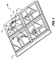
- the holder assembly 100 includes a holder 14 having one or more pockets 16, a plurality of printed sheets 18, such as photographic prints, are disposed in the pockets 16.
- a plurality of inserts 12 are also disposed in the pockets 16 along with the printed sheets 18.
- the pockets 16 each have a transparent wall 19 and the printed sheets 18 face the transparent walls 19, exterior to respective printed sheets 18.
- Inserts 12 are disposed in the pockets 16 between the printed sheets 18 and respective transparent walls 19.
- Within a pocket 16 an insert 12 overlaps the printed sheet 18.
- the printed sheets 18 can be viewed within the pockets 16 looking through the respective inserts 12.
- Each insert 12 is held within a respective pocket 16, in the same manner as the printed sheet 18. With the holders 14 shown in the figures, the insert 12 is held by frictional contact or entrapped or is held by a combination of the two.
- the inserts 12 each have a support layer 21 and an ink receptive layer 20 formed on the support layer.
- the ink receptive layer 20 and support layer 21 are both transparent to visible light. It is preferred that the insert 12 is sized to fully cover the printed sheet 18 and that the ink receptive layer 20 covers an entire surface of the insert 12, such that the ink receptive layer 20 fully overlaps the underlying printed sheet 18. This provides a uniform visual image and maximizes the available area for an invisible encodement.
- the photograph holder assembly 100 allows a user to arrange and rearrange, as desired, printed sheets 18 and inserts 12 having encodements of supplement information relating to the individual printed sheets 18.
- the user is able to edit sound files or other information without changing the printed sheets 18 or holder 14.
- one or more of the inserts 12 has an ink deposit 22 carried by a respective ink receptive layer 20.
- the ink deposit 22 is transparent to visible light and is preferably invisible under ordinary lighting conditions, that is, the ink deposit 22 absorbs little, if any, light in the visible region of the electromagnetic spectrum (i.e. in the range of about 400 nm to about 700nm).
- the ink deposit 22 does produce a detectable image in a radiation band outside the visible spectrum, as a result of reflection, transmission, or luminance.
- the frequency range or ranges of the invisible radiation modulated by the ink deposit 22 is dependent upon the characteristics of the material used for the ink deposit 22.
- infrared radiation or ultraviolet radiation or both can be used.
- the material absorbs or emits in the infrared (IR) region of the spectrum, in particular the light absorbs light between 800nm and 1200nm. Preferable the material absorbs light above about 850nm. In the event the material absorbs some light in the visible region, the material should be used at relatively low concentration so that the material can be detected by the sensor yet will not interfere with viewing any underlying information or image.
- the ink is deposited on the ink receptive layer 20 on an image-wise basis.
- the image formed by the ink deposit 22 is preferably that of one or more encodements such as a two-dimensional bar codes.
- Each encodement overlies a particular pocket and is, preferably, encoded supplemental information relating to the underlying printed sheet.
- a printed sheet 18 can be associated with the encodement by placing and keeping the printed sheet 18 in the same pocket 16 as the insert 12 bearing the encodement.
- the encodement can be output using a detector without removing the insert 12 from the pocket 16.
- the data in the encodement can include subject specific information, such as sound recorded when the picture was taken, for playback at the time of viewing the photographic print or other use.
- the form of the encoded data is not critical to the invention.
- the encodement can be in accordance with Standard PDF 417 and the LS49042D Scanner System marketed by Symbol Technologies, Inc., of Holtsville, New York; or the encodement scheme marketed as Paper Disk by Cobblestone Software, Inc., of Lexington, Massachusetts.
- a two-dimensional bar code can store a large data block.
- the amount of encoded data stored depends on the size of the surface bearing the ink deposit 22. For example, if the surface is 4" by 5" the bar code can store up to 80,250 pixels of data.
- the data stored is at least 500 pixels per square inch, preferably at least about 1000 pixels per square inch and most preferably at least about 1500 pixels per square inch.
- the data stored is between about 500 and 5000 pixels per square inch, preferably between about 1000 and 5000 pixels per square inch and most preferably about 1500 and 5000 pixels per square inch.
- a visible ink image can additionally be printed on the ink receptive layer 20, if desired; however, such a visible image is of limited usefulness, since the visible image interferes with viewing of the underlying photograph.
- the term "visible image” is used herein in a broad sense that is inclusive of marks, such as lines and borders; pictorial content; and alphanumeric characters and other indicia.
- the printed sheets 18 and inserts 12 can be fastened to each other; however, this is not preferred. It is preferred that the inserts 12 and respective printed sheets 18 are freely separable, since this allows the user to rearrange printed sheets 18 and inserts 12 as desired. This is particularly useful when the printed sheets 18 are photographic prints and the inserts 12 have sound recordings. Freely separable photographs and inserts 12 can be rearranged individually, or replaced by newly created inserts 12, as desired. This allows easy, simple editing of insert/printed sheet combinations.
- the holder 14 has one or more pockets 16.
- the number and arrangement of pockets 16 can be adjusted to meet different usages.
- Pockets 16 can be separated by dividers 26.
- Each pocket 16 has a wall 19 and defines an empty space 30 behind the wall 19. Behind the space 30 is a backing 34.
- Another pocket 16 or array of pockets 16 can be joined to the opposite side of the backing 34.
- the backing 34 can be opaque or transparent.
- the empty space 30 can receive and support one or more printed sheets 18 and respective insert or inserts 12.
- printed sheets 18 are generally treated herein as having a viewable image on only the front surface, but it will be understood that the printed sheet 18 could also have an image on the opposite surface which could also face a second wall.
- a second insert 12 could also be provided. It is generally desirable that the space 30 in each pocket 16 be sized to accommodate only a single printed sheet 18 and insert 12 or a pair of printed sheets 18 positioned back-to-back and an insert 12 for each printed sheet 18, since this allows full viewing of the front face of each printed sheet 18 and maintains the printed sheets 18 in position within the spaces 30 in an array predetermined by the arrangement of the pockets 16.
- the outward configuration of the photograph holder assembly 100 is not critical.
- the holder 14 is joined to a binding edge 13 to provide a jacket 10 in the form of an album leaf.
- the holder 14 and binding edge 13 can be continuous and made of the same material or can be made of different materials and adhered or fastened together.
- the binding edge 13 can be reinforced relative to the holder 14, if desired.
- the binding edge 13 is adapted to receive a binding 25.
- a plurality of album leaves 10 are connected together using the binding 25 to provide an album 24.
- a wide variety of different binding edges 13 can be used as appropriate for particular bindings 22.
- the binding edge 13 can have a series of spaced holes and the binding 22 can be a multiple ring binder or similar retainer.
- the binding edge 13 can have a flat portion and the binding 22 can be a compression binder or stitched book binding.
- the album pages 10 are flexible and each pocket has an opening 23 on one side.
- the wall 19 is flexible and is adhered to a flexible or rigid backing 34 by a layer 32 of adhesive.
- the wall 19 is reversibly removable from the backing 34 for placement and removal of printed sheets 18 from the space 30.
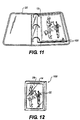
- the jacket 10 is three-dimensional.
- the holder includes a divider in the form of a picture frame and a wall joined to the frame. (A backing also joined to the frame is not shown.)
- the printed sheet 18 and insert 12 are held behind the wall within a pocket.
- the jacket 10 can have other configurations and is not limited to a particular size or shape, except as required by a particular printed sheet.
- the printed sheet 18 in the pocket 16 or pockets 16 of the jacket 10 can be photographic prints or other printed matter or even non-printed matter.
- the jacket 10 is discussed herein primarily in terms of viewable printed matter (also referred to herein as "printed sheets 18") and album leaves. It will be understood that like considerations apply to assemblies including other jackets 10 such as picture frames and to other uses.
- the invention is generally discussed herein in terms of inkjet printable inserts. It will be understood that the assembly 100 is not limited to any particular printing method. Ink and insert 12 compositions can be varied to meet the requirements of different printing methods.
- the wall and backing or a pair of walls are connected together at the dividers (illustrated in Figures 6-10 schematically as boxes).
- the dividers 26 are each formed by a juncture between the wall 19 and backing 34 or adjoining walls 28a,28b and can include an interlayer of adhesive or double sided tape or the like.
- the wall or walls can be reversibly releasable from the juncture or can be permanently attached.
- the juncture can also be an adhesive free union provided by sonic welding, solvent welding or other means. Mechanical fasteners are usable, but cumbersome and not preferred.
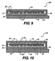
- the album leaf can have a pair of walls and spaces on either side of a backing. Referring to Figure 9, the backing is not present. In this case, wall 19a is joined to wall 19b at the junctures.
- the insert 12 can be positioned in a pocket 16 with the ink receptive layer 20 of the insert 12 facing the printed sheet 18.
- Ink receptive layers 20 can be placed on both the inner and the outer surfaces 38,40 of the insert 12.
- Figures 9-10 illustrate the assembly of Figure 6 modified by placing the ink receptive layer 20 on the inner surface of the insert 12 and on both surfaces of the insert 12, respectively. Similar modifications can be made in other configurations, such as those shown in Figures 7-8.
- an ink receptive layer 20 on the inner surface of the insert 12 presents a risk of ink transfer from the ink receptive layer 20 into the photograph.
- an ultraviolet absorber can be provided on or in the support or in the ink receptive layer 20 to protect the ink deposit 22 from ultraviolet light induced degradation.
- Materials used as ultraviolet light absorbers on photographic prints are suitable for this purpose, such as benzotriazole stabilizers marketed by Eastman Kodak Company of Rochester, New York as Tinuvin®327 and Tinuvin®328.
- the ink deposit 22 is on the outer surface of the insert 12, the risk of transfer is avoided. (The support of the insert 12 is normally impervious to ink.) This risk of transfer can also be avoided by limiting the usage of the inner surface.
- a manufacturer could print a trademark or other indicia on an ink receptive layer 20 of an inner surface of a insert 12. The outer surface would have an ink receptive layer 20 for later use by a consumer. This is illustrated in Figure 11. A trademark or the like on an inner surface of the insert 12 is indicated by the letter "Z".
- the wall supports and retains the printed sheets 18 and inserts 12 within the pockets 16.
- Suitable materials vary with intended use. For example, if the jacket 10 is a picture frame, then it is desirable that the wall be sufficiently rigid to be self supporting. Suitable materials for the wall in this use, include glass and acrylic plastic. If the jacket 10 is an album leaf, then it is preferred that the wall is flexible.
- the insert 12 and wall are both transparent to allow viewing of the printed sheets 18 within the pockets 16. This transparency is not perfect, but is preferably sufficient to not detract from the viewing experience.
- the assembly can have one or more opaque or translucent regions, but it is highly preferred that the non-opaque regions be positioned to not overlie the front faces of the printed sheets 18 in the pockets 16.
- the ink receptive layer 20 is adapted to adhere to the support layer 21 and to receive ink deposited by a specific type of printer, such as an ink jet printer. Suitable combinations of materials for the support layer 21 and ink receptive layer 20 are well known to those of skill in the art. (It will be understood that the terms “support layer 21" and “ink receptive layer 20" can each be inclusive of multiple layers.)
- the insert is invisibly printed using an ink jet printer and the insert can have the chemical and physical characteristics of ink jet transparencies and other receivers disclosed in U.S. Patents No. 4,460,637; 4,555,437; 4,642,247; 4,741,969; 4,956,230; 5,198,306; 5,662,997; 5,714,245. Because of its intended purpose, this embodiment of the invention is subject to some constraints that distinguish the insert from ordinary ink jet receivers.
- the printed insert has an invisible ink deposit 22. It is highly desirable that ink receptive layers 20 are optimized for use with particular inks so as to reduce the risk of defective printed inserts having unreadable bar codes.
- ink jet printers since these printers often produce a copy that is initially wet and subject to smearing. It is also desirable that the ink receptive layer 20 and intended inks be simultaneously optimized to initially provide and maintain high resolution of the ink deposit 22.
- Drying time is an important parameter. For general use, it is preferred that the drying time for ink jet ink deposited on the ink receptive layer 20 is less than three minutes. One to two minutes drying time is more preferred and 15 seconds to one minute is still more preferred. These drying times are based on a determination of ink transfer or no transfer to bond paper pressed against the ink deposit 22. Drying time is a function of the amount of ink deposited and the area and other physical characteristics of the deposited ink, such as the concentration of infrared detectable material in the ink. For bar codes, these characteristics are fully predictable in a particular use. For example, bar codes printed on the inserts have predictable sizes.
- ink lay down is predictable and is generally limited to two values corresponding to the binary numbers 0 and 1.
- the size of a unit area and contrast required between different areas is a function of the detector used, the working range for that detector, and the materials used in the inks.
- Total coverage and distribution of ink in a bar code is a function of the allowable patterns provided by a particular code.
- the inks and ink receptive layers and support layers can also be adjusted to have other characteristics known in the art for black and colored ink jet inks and ink receivers.
- the insert not be subject to curling with changes in environmental humidity.
- a deposited dot of ink spread on the ink receptive layer 20 only to a limited extent and in a predictable manner.
- An acceptable increase in diameter of a deposited dot of ink is from 10 micrometers to 200-250 micrometers.
- the insert and wall in combination have a haze value, as measured by American Society for Testing and Materials standard: ASTM D 1003-97, of less than 10 percent (hereafter referred to as "haze value"). A haze value of less than 7 percent is more preferred and a haze value of less than 5 percent is still more preferred. It is preferred that the insert and wall in combination have a transmittance of more than 70 percent, as measured by American Society for Testing and Materials standard: ASTM D 1746-97. A transmittance of greater than 80 percent is preferred and greater than 90 percent is more preferred.
- the following patents disclose materials and methods relating to the above features: U.S. Patents Nos. 4,460.637; 4,555,437; 4,642,247; 4,741,969; 4,956,230; 5,198,306; 5,662,997; 5,714,245.
- ink receptive layers 20 having suitable drying times for use with these invisible ink jet inks are disclosed in U.S. Patents Nos. 4,741,969; 4,555,437; 5,198,306; and 4,642,247.
- Ink jet transparencies. having suitable ink receptive layers 20 are marketed by Eastman Kodak Company of Rochester, New York, as Kodak Inkjet Photo Transparency Film. Jackets 10 can use these ink jet transparencies as inserts.
- the invisible material is a luminescent material.
- a luminescent material is defined as any material which absorbs light and then emits light at another region of the electromagnetic spectrum which may be detected by some sensor device. While most luminescent materials absorb light at a particular wavelength and emit light at longer wavelength the materials of this invention are not limited to such restrictions. In fact materials where the opposite is true, materials sometimes referred to as up-converters or up-conversion materials. would also be useful for this invention. Such materials are described in Indian J. Of Pure and Appl. Phys ., 33 , 169-178, ( 1995 ).
- the invisible, luminescent materials can be either dyes, pigment, or any other material possessing the desired absorption properties. And the fluorescent dyes can absorb either in the UV, visible or in the infrared region of the electromagnetic spectrum at a concentration such that the data can be detected by a sensor and the data does not interfere with viewing the underlying information or image.
- Table 1 lists examples of suitable UV or visible absorbing materials which upon illumination with an appropriate light source, fluoresce in the visible or near IR region of the electromagnetic spectrum.
- Compounds A, B, C are general representations of coumarins, fluoresceins and rhodamines respectively. Dyes of these classes are reviewed in Appl. Phys . B56 , 385-390 ( 1993 ). These molecules are highly luminescent and may be useful for the present invention.
- R 1 represents any group including a hydrogen, substituted alkyl (per-halogenated, branched, saturated or unsaturated), halogen atoms (Cl, Br, I), any aryl group (phenyl, naphthyl, pyrrlyl, thienyl, furyl, etc.) or acyl (amido, ester, or carboxy), any sulfonic acid groups or derivatives of sulfonic acids (sulfonamides, sulfuryl halides, nitro, or substituted ether group.
- R could be any group that allows these compounds to remain luminescent.
- T represents any of the following groups, OH, substituted or unsubstituted amino, a substituted amino group where the amino is a member of any ring, fused or otherwise.
- R 2 can be any substituted alkyl, aryl or acyl groups ( perfluoronated alkyl groups are particularly useful in this position).
- R 3 can be hydrogen, or substituted alkyl. When R 3 is aryl or CN these dyes are particularly useful for the present invention, these dyes absorb in the IR region of the electromagnetic spectrum.
- R 4 can be any substituted alkyl, aryl or acyl groups ( perfluoronated alkyl groups are particularly useful in this position).
- R 5 and R 6 can be hydrogen atoms or any combination of alkyl groups.
- R 5 and R 6 can represent groups necessary to form any ring (e.g. pyrrole, pyrimidine, morpholine or thiomorpholine).
- R 5 and R 6 may be part of a bicyclic ring system, fused onto the phenyl ring as shown in the general structure below. Fused molecules of this type are reviewed in Tetrahedron, Vol. 34 , No.38, 6013-6016, ( 1993 ). The impact of annulation on absorption and fluorescence characteristics of related materials is described in J. Chem. Soc., Perkin Trans . 2 , 853-856, ( 1996 ). Aromatics (polycyclic aromatics especially) such as shown in Table 2 are useful for this invention.
- X 1 , Y 1 , Z 1 can be any groups which allow these compounds to be luminescent.
- T 2 represents any substituted or unsubstituted amino or substituted or unsubstituted oxygen and W can be carbon, or nitrogen.
- W can be carbon, or nitrogen.
- X 1 , Y 1 or Z 1 are donor and acceptor groups on the same molecule as depicted on the so called "dansyl" molecule depicted as compound G.
- Anthracenes, pyrenes and their benzo derivatives are examples of fused aromatics. These materials are can be used individually or in combination with multiple components to form complexes which are luminescent.
- Sulfonated polyaromatics are particularly useful in water-based ink formulations.
- Lucifer yellow (H) dyes are often soluble in water and are comparatively stable and are described in Nature , 292 , 17-21, ( 1981 ).
- the commercial Lucifer yellow dyes were H where R 8 is any alkyl and X + represents a cation, necessary to balance the negative charge is useful for this invention
- the merits of this type of molecule and its luminescent properties have been disclosed in U.S. Patent No. 4,891,351 for use in thermal transfer applications.
- the stilbene class of dyes Table 3 are useful for the present invention. These dyes are very commonly used commercially as optical brightners for paper stock. Colourage 47-52, (1995) reviews fluorescent stilbene type lumiphores.
- X 2 and/or Y 2 can be any substituent or group that promotes absorption of this chromophore in the UV or short wavelength visible and subsequently emits light in the visible.
- Examples include but are not limited to halogens (Cl, I, etc.), alkyl (methyl, ethyl, butyl, iso-amyl, etc.) which may be used to increase organic solubility, sulfonic acid and its derivatives which may be useful for increasing water solubility, carboxylic acid groups which may be used for solubility but also as a position of oligomerization or polymerization. Also useful are amine derive substituents, which can be used to append groups for solubility purposes and polymerization but additionally may be used to manipulate the absorption characteristics. Stilbenes where X 2 and Y 2 are comprised of groups which allow for a donor and acceptor molecule in the same molecule are particularly useful for this purpose.
- Z 3 , Z 4 , Z 5 , and Z 6 represent any atoms that can be used to form a ring of any size or substitution with the proviso that the material is still luminescent.
- Z 5 and Z 6 represent heteroaromatic nuclei, such as benzoxazolium, benzothiazolium, benzimdazolium, or their naphthalene derivatives, which make these compounds highly fluorescent.
- Table 4 shows some highly fluorescent amine heterocycles that would be particularly useful for this invention.
- the highly fluorescent tetraphenylhexaazaanthracene (TPHA, L) is atmosphere stable and thermally stable up to 400°C (see J. Am. Chem. Soc . 120 , 2989-2990, (1998)and included references). Such properties would be extremely useful for encodement of data where archival stability is expected to be an important issue.
- the diaminobipyridine compound M described in J. Chem. Soc., Perkin Trans. 2, 613-617, ( 1996 )was found to be highly fluorescent.
- the benzimidazalones N such as disclosed in Tetahedron Letters, 39 , 5239-5242, (1998), are also highly fluorescent when incorporated into certain environments.
- the aromatic group (Ar) can be a simple phenyl or more intricate heteroaromatic groups (imidazolo, benzoxazolo, indole, etc.).
- Table 5 contains another general class of useful dyes for the application described in the present invention.
- Compounds O, P, and Q represent several classes of metallized dyes which are included in the scope of the present invention.
- Boron complexes such as compound ( O ) are very fluorescent, stable and easily synthesized from commercially available materials. Such materials are disclosed in J. Am. Chem. Soc . 116 , 7801-7803, ( 1994 ).
- X3 represents atoms necessary to form an aromatic or heteroaromatic ring, L 1 and/or L 2 could be halogens, ether or any other ligand which commonly has an affinity for boron metal.
- Bipyridyl metal complexes such as (P) are luminescent, as disclosed in Chem. Rev.
- X3 could be an atom which form either an aromatic fused ring forming a phenanthroline complex or saturated ring which could restrict from rotation the bipyridyl functions.
- M represents any metal that would provide a luminescent complex (e.g. Ru or Re)or a metal which when complexed with the bipyridyl ligand quenches luminescence in a photographic manner.
- Compound (Q) represents the lanthanide complexes which are useful for thermal transfer imaging as disclosed in U.S. Patent No. 5,006,503.
- Lanthanide metal complex dyes have UV absorbance and typically large Stokes' shifts. Dyes such as the phenyloxozolium compounds, generally depicted as in Table 6, are very fluorescent and have the added feature that the fluorescent signal is long lived, as disclosed in Photochemistry and Photobiology , 66 (4), 424-431,( 1997 ). When the R-groups represent donor (D) and acceptor (A)groups on the same molecule as depicted in structure S, then these materials possess superior luminescent properties.
- the materials discussed in the previous examples absorbed light in either the UV or visible region of the electromagnetic spectrum . These materials have several advantages for use in the application described in the present invention. Often the materials are atmospherically stable, they are commercially available since they have been used extensively in non-photographic applications and finally good optical properties can been had (e.g. large Stokes' shifts, high fluorescence quantum yield, long excited state lifetimes, etc.
- the materials in the next series of examples absorb light in the IR and for the most part emit further into the IR. Since these materials emit beyond the absorption of the other possible colorants on articles, IR luminescent materials can be detected easier from background colorants. The next several materials are typical IR materials useful for this invention.
- Table 7 contains a general structure depicting a phthalocyanine or naphthalocyanine compound.
- Phthalocyanines are well known in the photographic industry and are reviewed in Molecular Luminescence: An International Conference. , New York, W. A. Benjamin, 295-307, ( 1969 ) and Infared Absorbing dyes: Topics in Applied Chemistry, Edited by Masaru Matsuoka, New York, Plenum Press, 1990. These materials have been used in electroconductive applications, as absorber dyes for photothermographic printing and as colorants in inks.
- Several well known properties of the phthalocyanines and their extended analogs, naphthalocyanines are high fluorescence efficiencies and superior thermal and light stability.
- Compound T depicts a general structure of a phthalocyanine or naphthalocyanine.
- X5, X6, X7 and X8 represent atoms necessary to form a ring.
- the ring is often aromatic or heteroaromatic such as phenyl, 1,2-fused naphthyl, 1,8-fused naphthyl or larger fused polyaromatics such as fluoroanthrocyanine.
- the rings may be substituted in any way in the spirit of this invention provided that the materials is still luminescent. In fact differential substitution can be used to attenuate the physical properties (e.g. light stability and solubility) or enhance the optical properties of a material (e.g. Fluorescence efficiency or Stokes' shift).
- the rings may contain functional groups through which oligomerization can be accomplished.
- the (X5-8)-groups may be the same or different leading to symmetrical or unsymmetrical materials respectively.
- the metal atom (M 2 ) can be any metal with the proviso that it allows for luminescent materials.
- the substituent M 2 can also represent two hydrogen atoms, these materials are usually referred to as "non-metallized" (na)phthalocyanines.
- Some metals can possess additional "axial" ligands (e.g. Al and Si) which are useful for appending additional functional groups to alter the properties of the dyes. Additionally these groups prevent chromophore aggregation which may perturb the luminescent properties of the chromophores.
- These ligands also useful points of attachment to oligerimerize or form dendrimers of these materials as disclosed in Thin Solid Films , 299,63-66, (1997) and Angew. Chem. Int. Ed . 37 (8), (1092-1094), ( 1998 ).
- a related class of materials is depicted in Table 8. Compound U is classified as a "sub"-phthalocyanine and is disclosed in J. Am. Chem. Soc .
- n could be 0 or any integer (e.g.
- A is a group that is appended to the central chain carbon or atom.
- the group A can be any alkyl, aromatic or heteroaromatic group.
- A can be any group with the proviso that the dye is still luminescent.
- Y2 and Y3 could be independently one of the following groups: N, O, S, Se, or Te, additional C(alkyl) 2 which forms the indole nucleus, well recognized by anyone skilled in the art as an indole ring. Additionally when Y 2 or Y 3 is nitrogen then it is substituted with an appropriate group, forming what is recognizable as an imidazolium ring by any skilled in the art.
- Z 6 and Z 7 represent atoms necessary for forming a saturated aromatic or unsaturated non-aromatic ring.
- the ring so formed could be phenyl, naphthyl or any other fused aromatic.
- the ring could be any aromatic or non-aromatic heteroatom containing ring (e. g. pyridyl, quinoyl, etc.)
- R 12 or R 13 represent any of the possible nitrogen substituents well known by any skilled in the art.
- R 12 or R 13 may be independently saturated substituted or unsubstituted alkyl (e.g.
- R 12 and R 13 may also be charged groups (cationic, anionic or both). In cases where the R 12 and or R 13 are charged and a net charge exists on the dye, there exist a combination of counterions to balance the charge. For example, if R 12 and R 13 are both sulfoalkyl the net charge on the chromophore may be -1 and hence would be charge balanced with an appropriate cation (e. g.
- R 12 and R 13 are simple uncharged alkyl groups such methyl, then the dye may have a net +1 charge and hence have to be charge balanced with a negative anion (e. g. perfluorobutyrate, I-, BF4-, etc.).
- R 12 and R 13 could be groups necessary to incorporate the material in an oligomer or polymer.
- the dye may be incorporated into the polymer backbone or pendant. Additionally the polymer may incorporate this material by non-covalent forces (charge-charge interactions, encapsulation, etc.). Long chain cyanines are often bridged.
- the bridge could be any saturated structure of any size, preferably 5, 6, 7 membered. Such ring may be fuctionalized with the usual groups alkyl (e.g. methyl, t-butyl) carboxlic acid (and its derivatives), sulfonic acids (and its derivatives) halogen, aromatic and heteroaromatic.
- Group B could be the usual chain substituents, halogen (preferable Cl), phenyl, heteroaryl (e. g. furyl, thienyl, etc.), ethereal (e. g.
- B1 could represent a point of attachment for oligomerization or polymerization. It is noted that m represents an integer from 1-3 as dyes containing such bridging are well known in the art.
- Z groups represent atoms necessary to for fused rings. Each Z group represents any ring which allows these dyes to be luminescent.
- Y 4 and Y 5 represent atoms necessary to form the typical dye nuclei and could anything which allows the material to be luminescent. The material shown in Table 11 illustrates another useful feature.
- X 11 and X 12 represent the atoms necessary to for a ring from the nitrogen atom of the hetero-nucleus to the chromophore chain. Typically forming a 5-member or six member ring. Ridigization of chromophores as depicted in the materials of Tables 10 and 11 is known to enhance the luminescence. Another well known class of luminescent materials is depicted in Table 12. This class of materials are known as squaraine dyes or squarylium dyes. The use of organic solubilized squaraines for antihalation protection in IR sensitive AgX applications has been described in published PCT patent application WO 96/35142). These dyes have been also been disclosed for use as IR absorbing elements in laser addressable imaging elements in published European Patent Application EP 0764877A1.
- Squaraine dyes are well known to have good thermal stability, another preferred feature for any material of this invention.
- Z123 and Z13 independently represent any substituted aromatic or heteroaromatic nucleus.
- Typical aromatic nuclei include phenyl, naphthyl, pyrrylium, thiopyrrylium, or any other group which provides that the material is luminescent or absorbs a wavelength in the IR or UV region of the spectrum.
- Heteroaromatic rings could be but not limited to benzoxazolium, benthiazolium, quinoline or any other group which provided that the material is luminescent. It is also noteworthy to mention that the center ring does not have to feature the negative charge oxygen (O-). In fact squaraines where the central chain atom is either carbon or nitrogen have been disclosed in U.S. Patent No. 5,227,499 and U.S. Patent No. 5,227,498.
- IR materials are illustrated in Table 13. These squaraine and croconium dyes are disclosed in Sensors and Actuators B, 38-39 , 202-206 ( 1997 ) and Sensors and Actuators B, 38-39 , 252-255 ( 1997) .
- the croconium dyes like squaraines are well known to have good thermal stability, another preferred feature for any material of this invention.
- Z12 and Z13 indenpently represent any substituted aromatic or heteroaromatic nucleus. Typical aromatic nuclei include phenyl, naphthyl, any other group which provided that the material is luminescent. pyrrylium, thiopyrrylium. Heteoaromatic includes but not limited to benzoxazolium, benthiazolium, quinoline or any other group which provided that the material is luminescent. wherein Z14 represents any substituted aromatic or heteroaromatic nucleus.
- ком ⁇ онент with a photographic developer
- host-guest or molecular recognition e.g. metal complexation, chromophore-chromophore interactions, coupler-developer reaction. etc.
- Equation 1 depicts the photo-conversion of a material into a material with additional "eximer fluorescence" ( J. Chem.Soc.Chem. Commun. , 591 ( 1992 )).
- the process uses light to generate a new material which could be easily a luminescent material.
- a second point relevant to this patent is illustrated, that is, that a second stimulus (heat in the above example) may be used to reverse a material from a colored (or luminescent) state to a colorless (or non-luminescent) state.
- the encodement may not necessarily be due to the luminescent material directly but may be due to its removal from a luminescent background.
- Equation 2 shows another type of activation of a material ( Angew. Chem. Int. Ed. Engl ., (24),2817-2819, ( 1997 )).
- a material (or its luminescence) may be "turned on” or “off” with redox chemistry.
- the oxidation may come about by simple post-coating reaction with a molecular oxidant or a more complicated photographic process (generation of an oxidized color developer). Equation 2 also illustrates the possibility of a reversible system.
- Equation 3 illustrates yet another possible way of generating a luminescent compound.
- This process involves the selective complexation ("molecular recognition” or "host-guest") of one non-luminescent component (dye-ligand) by another (Cu 2+ ion) to in this case convert the material to a luminescent material (Angew. Chem. Int. Ed . 37 ,772-773, ( 1998 )).
- This example shows the formation of a new material without the possibility for reversal.
- molecular recognition can be used to form a transient luminescent species that can be reverted back to the non-luminescent material (J. Mater. Chem. , 8 (6), 1379-1384, ( 1998 )).
- a luminescent material could be converted to a non-luminescent material for the encodement.
- the mechanisms by which these materials luminesce or do not luminesce and their physical attributes have been thoroughly reviewed ( Chem. Rev. , 97 , 1515-1564, ( 1997 )).
- the materials and methods for generating luminescence described within this reference are useful in the practice of this invention.
- X and Y are CH or COR in any combination.
- R can be substituted silyl group (e.g. trimethylsilane, tributylsilane, trichlorosilane triethoxysilane, etc.) or any group that could be used to make the above compounds oligomeric or prevent dye aggregation.
- Dye 1 polymeric aluminum phthalocyanine dye (commercially available from Eastman Chemical as NIRF ink solution).
- the methods of applying the invisible material on the ink receptive layer can be any digital imaging mechanism, including inkjet, direct thermal or thermal transfer printing, electrophotography, molecular recognition, thermal, and light induced chemical reaction, such as oxidant, reductant or metal complexation, of leuco dyes.
- Other methods include the use of commercial color imaging systems, such as CycolorTM system available from Cycolor Inc., 8821 Washington Church Road, Miamisburgh, Ohio 45342 and microcapsules (cyliths) containing colored dyes are selectively imagewise exposured with sequential red, green and blue light. The light initiates the hardening of the shell of the exposed bead rendering them resistant to destruction during the processing step.
- the beads are compressed and the non-hardened beads are crushed releasing their colored dye which is the complimentary to the exposure color (red/cyan, green/magenta, blue/yellow).
- red/cyan, green/magenta, blue/yellow the complimentary to the exposure color
- ink deposit 22 is generally discussed herein in terms of ink jet printing, but it will be understood that like considerations apply to other printing methods.
- the concentration of the invisible material in the ink solution can be 0.005% ⁇ 1% by weight, preferably 0.01% ⁇ 0.1% by weight.
- a suitable surfactant such as surfynol® 465 surfactant (an ethoxylated dialcohol surfactant sold by Air Products and Chemicals, Inc.)can be added at 0.5%-2% by weight, with the presence of 2-10% glycerol, 2-10% diethyleneglycol, 2-10% propanol, and 0%-2% triethanolamine.
- Commercial inkjet printers such as HP690C or Epson Stylus Color 200 was used for the testing, with the printing resolution of 300 or 360 dpi.
- Either stepwedge files or 2-D bar-code encoding compressed sound file can be printed digitally onto various supports at the visual reflection density of 0.01-0.3, preferably 0.05-0.1.
- An assemblage of thermal dye transfer such as described in US 4,839,3can be used.
- This assemblage comprises: (a) a dye-donor element that contains the invisible material, and (b) a dye-receiving element which is in a superposed relationship with the dye-donor element so that the dye-layer of the donor element is in contact with the dye-image receiving layer of the receiving element.
- the dye-receiving element is the ink receptive layer of the holder.
- the assemblage may be pre-assembled as an integral unit when a single luminescent dye material is transferred. This can be done by temporarily adhering the two elements together at their margins. After transfer, the dye-receiving element is then peeled apart to expose the dye transfer image. More than one dye donor sheet containing different luminescent materials can also be used and multiple luminescent 2D bar-code images can be transferred consecutively.
- the luminescent material in the dye-donor element is dispersed in a polymer binder such as a cellulose derivatives, e. g., cellulose acetate hydrogen phthalate, cellulose acetate propionate, cellulose acetate butyrate, cellulose triacetate or any of the materials described in U. S. Pat. No. 4,700,207.
- the binder may be used at a coverage of from about 0.1 to about 5 g/m 2
- the luminescent material can be used at a coverage of from about 0.02 to about 0.2 g/m 2 .
- the support for dye-donor element in this invention can be any material that is dimensionally stable and can withstand the heat of the thermal printing heads.
- Such materials include polyesters such as poly(ethylene terephthalate); polyamides; polycarbonates; cellulose esters such as cellulose acetate; fluorine polymers such as polyvinylidene fluoride or poly(tetrafluoroethylene-co-hexafluoropropylene); polyethers such as polyoxymethylene,; polyacetals; polyolefins such as polystyrene, polyethylene, polypropylene or methylpentane polymers; and polymides such as polymide-amides and polyetherimides.
- the support may be coated with a subbing layer, if desired, such as those materials described in U. S. Pat. No. 4,695,288.
- the ink solution of Formulation 1 can be modified by substituting for the fluorescent dye is a UV-absorbing, visible fluorescing dye (dye 2) at a final concentration of dye 2 is 0.1% by weight in the ink solution.
- the fluorescent dye is a UV-absorbing, visible fluorescing dye (dye 2) at a final concentration of dye 2 is 0.1% by weight in the ink solution.
- the ink solution of Formulation 1 can be modified by substituting for the fluorescent dye is a visible-absorbing, visible fluorescing dye (dye 3), and that the final concentration of dye 3 is 0.01% by weight in the ink solution.
- the fluorescent dye is a visible-absorbing, visible fluorescing dye (dye 3)
- the final concentration of dye 3 is 0.01% by weight in the ink solution.
- the ink solution of Formulation 1 can be modified by substituting for the fluorescent dye is an infrared-absorbing, infrared fluorescing dye (dye 4, a cyanine dye), and that the final concentration of dye 4 is 0.01% by weight in the ink solution.
- the fluorescent dye is an infrared-absorbing, infrared fluorescing dye (dye 4, a cyanine dye)
- the final concentration of dye 4 is 0.01% by weight in the ink solution.
- a luminescence dye-donor element can be prepared by coating the following layers in the order recited on a holder:
- the element of Formulation 5 can be modified by use as the luminescent dye a UV absorbing, visible fluorescing dye (dye 6 , a coumarin dye).
- the element of Formulation 5 can be modified by use as the luminescent dye a UV absorbing, visible fluorescing dye (dye 7 , an europium complex).
- the element of Formulation 5 can be modified by use as the luminescent dye an infrared-absorbing, nonfluorescing dye (dye 8 ) at a final concentration of dye 8 is of 200 ppm by weight in the ink solution.
- an infrared-absorbing, nonfluorescing dye (dye 8 ) at a final concentration of dye 8 is of 200 ppm by weight in the ink solution.
- the dye-donor element may be used in sheet form or in a continuous roll or ribbon.
- the reverse side of the dye-donor element may be coated with a slipping layer to prevent the printing head from sticking to the dye-donor element.
- a slipping layer would comprise a lubricating material such as a surface active agent, a liquid lubricant, a solid lubricant or mixtures thereof, with or without a polymeric binder.
- Preferred lubricating materials include oils or semicrystalline organic solids that melt below 100 °C such as poly(vinyl stearate), beeswax, perfluorinated alkyl ester polyethers, poly(caprolactone), silicone oil, poly(tetrafluoroethylene), carbowax, poly(ethylene glycols).
- Suitable polymeric binders for the slipping layer include poly(vinyl alcohol-cobutyral), poly(vinyl alcohol-co-acetal), poly(styrene), poly(vinyl acetate), cellulose acetate butyrate, cellulose acetate propionate, cellulose acetate or ethyl cellulose.
- the amount of the lubricating is generally in the range of about 0.001 to about 2 g/m 2 .
- the lubricating material is present in the range of 0.01 to 50 weight %, preferably 0.5 to 40, of the polymer binder employed.
- the support of the holder can be transparent film such as a poly(ether sulfone), a polymide, a cellulose ester such as cellulose acetate, a poly(vinyl alcohol-co-acetal) or a poly(ethylene terephthalate).
- the ink receptive layer can comprise, for example a polycarbonate, a polyurethane, a polyester, polyvinyl chloride, poly(styrene-co-acrylonitrile), poly(carprolactone) or mixtures thereof.
- the ink receptive layer can be present in the amount of about 1 to about 5 g/m 2 .
- Thermal printing heads which can be used to transfer dye from the dye-donor elements are available commercially. There can be employed, for example, a Fujitsu Thermal Head (FTP-040 MCSOO1), a TDK thermal head F415 HH7-1089 or a Rohm Thermal Head KE 2008-F3.
- FTP-040 MCSOO1 Fujitsu Thermal Head
- F415 HH7-1089 TDK thermal head
- Rohm Thermal Head KE 2008-F3 Rohm Thermal Head KE 2008-F3.
- the playback device is preferably a hand held wand reader or a digital camera engineered to operate in a dual role as a playback device.
- the sensor of this device can have integrated CCD or CMOS technology with a LED illumination source, decoding software and circuits.
- One example of such a device would also have the mechanism to playback the file as an analog sound file.
Landscapes
- Business, Economics & Management (AREA)
- Engineering & Computer Science (AREA)
- Educational Administration (AREA)
- Educational Technology (AREA)
- Physics & Mathematics (AREA)
- General Physics & Mathematics (AREA)
- Silver Salt Photography Or Processing Solution Therefor (AREA)
- Sheet Holders (AREA)
- Inks, Pencil-Leads, Or Crayons (AREA)
- Ink Jet Recording Methods And Recording Media Thereof (AREA)
Claims (10)
- Halteanordnung mit:dadurch gekennzeichnet, dasseinem Halter mit ein oder zwei Taschen, wobei die Taschen jeweils eine transparente Seite aufweisen;einer Vielzahl von Prints, die in den Taschen angeordnet sind, wobei jeder Print einer entsprechenden Seite zugewandt ist;
eine oder mehrere Einsätze in diesen Taschen zwischen entsprechenden Prints und entsprechenden Seiten angeordnet sind, wobei die Einsätze jeweils eine Tinte aufnehmende Schicht und eine Trägerschicht umfassen und die Schichten gegenüber sichtbarem Licht transparent sind. - Halteanordnung nach Anspruch 1, dadurch gekennzeichnet, dass die Einsätze und die Prints frei trennbar sind.
- Halteanordnung nach Anspruch 1 oder 2, dadurch gekennzeichnet, dass mindestens eine der transparenten Einsätze einen Tintenvorrat in einer entsprechenden Tinte aufnehmenden Schicht umfasst, wobei der Tintenvorrat sichtbarem Licht gegenüber transparent ist.
- Halteanordnung nach Anspruch 1, 2 oder 3, dadurch gekennzeichnet, dass der Tintenvorrat gegenüber Infrarotstrahlung nicht transparent ist.
- Halteanordnung nach Anspruch 1, 2, 3 oder 4, dadurch gekennzeichnet, dass die Tinte aufnehmende Schicht eine Trocknungszeit von weniger als 3 Minuten aufweist.
- Halteanordnung nach Anspruch 1, 2, 3,4 oder 5, dadurch gekennzeichnet, dass die Tinte aufnehmende Schicht einen kombinierten Trübungswert von weniger als 10 Prozent aufweist.
- Halteanordnung nach Anspruch 1, 2, 3,4, 5 oder 6, dadurch gekennzeichnet, dass die Taschen jeweils eine Vorderseite und eine gegenüberliegende Rückseite aufweisen und dass jede der Taschen zwei der Prints und zwei der Einsätze enthält.
- Halteanordnung nach Anspruch 1, 2, 3,4, 5, 6 oder 7, dadurch gekennzeichnet, dass die Tinte aufnehmenden Schichten zwischen den jeweiligen Trägerschichten und den jeweiligen Seiten angeordnet sind.
- Album mit
einer Bindung und
einer Vielzahl von fotografischen Halteanordnungen, die durch die Bindung gehalten sind, wobei jede Anordnung folgendes umfasst:dadurch gekennzeichnet, dasseinen Halter mit mindestens einer Vielzahl von Taschen, wobei die Taschen jeweils eine transparente Seite aufweisen;eine Vielzahl von Prints, die in den Taschen angeordnet sind, wobei jedes Print einer entsprechenden Seite zugewandt ist;
eine Vielzahl von Einsätze in diesen Taschen zwischen entsprechenden Prints und entsprechenden Seiten angeordnet sind, wobei die Einsätze jeweils eine Tinte aufnehmende Schicht und eine Trägerschicht umfassen und die Schichten gegenüber sichtbarem Licht transparent sind. - Album nach Anspruch 9, dadurch gekennzeichnet, dass mindestens eine der transparenten Einsätze einen Tintenvorrat in einer entsprechenden Tinte aufnehmenden Schicht umfasst, wobei der Tintenvorrat sichtbarem Licht gegenüber transparent und infrarotem Licht gegenüber nicht transparent ist.
Applications Claiming Priority (2)
| Application Number | Priority Date | Filing Date | Title |
|---|---|---|---|
| US335374 | 1999-06-17 | ||
| US09/335,374 US6139210A (en) | 1999-06-17 | 1999-06-17 | Photographic holder assembly and album |
Publications (3)
| Publication Number | Publication Date |
|---|---|
| EP1060909A2 EP1060909A2 (de) | 2000-12-20 |
| EP1060909A3 EP1060909A3 (de) | 2001-07-11 |
| EP1060909B1 true EP1060909B1 (de) | 2004-05-12 |
Family
ID=23311512
Family Applications (1)
| Application Number | Title | Priority Date | Filing Date |
|---|---|---|---|
| EP00201964A Expired - Lifetime EP1060909B1 (de) | 1999-06-17 | 2000-06-05 | Fototräger und Album |
Country Status (4)
| Country | Link |
|---|---|
| US (1) | US6139210A (de) |
| EP (1) | EP1060909B1 (de) |
| JP (1) | JP2001010267A (de) |
| DE (1) | DE60010576T2 (de) |
Families Citing this family (31)
| Publication number | Priority date | Publication date | Assignee | Title |
|---|---|---|---|---|
| US6431448B1 (en) * | 2000-05-11 | 2002-08-13 | Eastman Kodak Company | Keyed data-and-print album page |
| US6769829B1 (en) * | 2000-06-30 | 2004-08-03 | Avery Dennison Corporation | Drawable and/or traceable binder |
| US6761677B1 (en) * | 2000-09-22 | 2004-07-13 | Eastman Kodak Company | Album leaf and method and apparatus for making an album leaf |
| WO2002061736A2 (en) | 2001-01-29 | 2002-08-08 | The Mead Corporation | Dvd sleeve |
| US20030205895A1 (en) * | 2001-03-27 | 2003-11-06 | Scarbrough Joel Scott | Reflective printed article and method of manufacturing same |
| US6942413B2 (en) * | 2001-10-17 | 2005-09-13 | Bradley P. Lane | Disc management system |
| US20030184079A1 (en) * | 2002-04-01 | 2003-10-02 | Betzold Heather S. | Journal |
| US7270237B2 (en) * | 2003-07-24 | 2007-09-18 | Stanely T. Mandeltort | Waterproof document storage device |
| US20050060919A1 (en) * | 2003-09-23 | 2005-03-24 | Sun Yu | Greeting card incorporating ultraviolet light emitting diode |
| US20050206155A1 (en) * | 2004-03-17 | 2005-09-22 | Porreca Robert F | CD menu and song order control system |
| US20070020556A1 (en) * | 2005-07-25 | 2007-01-25 | Stravina Operating Company, Llc | Photosensitive articles and related manufacturing process |
| GB2432559A (en) * | 2005-11-28 | 2007-05-30 | Neville Simeon Conrad | Album in combination with bookmarks |
| JP4657256B2 (ja) * | 2007-06-14 | 2011-03-23 | オリンパス株式会社 | 画像観察方法及び印刷物収納用具 |
| JP5151746B2 (ja) * | 2008-05-13 | 2013-02-27 | 東洋紡株式会社 | 温度時間経歴を表示する製造工程チェックラベル |
| US9802438B2 (en) * | 2008-05-16 | 2017-10-31 | Laura J. Miranti | Board book photo album |
| USD622503S1 (en) * | 2009-07-20 | 2010-08-31 | Tai Ping Carperts International Ltd. | Carpet tile sample folder |
| US20110072694A1 (en) * | 2009-09-30 | 2011-03-31 | PenPals, LLC | Autographable card-type memorabilia |
| US8739442B2 (en) * | 2010-04-15 | 2014-06-03 | Mike Shape | Auto photo caddy |
| USD641781S1 (en) * | 2010-07-28 | 2011-07-19 | Konami Digital Entertainment Co., Ltd. | Card folder |
| WO2012094409A2 (en) | 2011-01-05 | 2012-07-12 | Nitto Denko Corporation | Wavelength conversion perylene diester chromophores and luminescent films |
| CN105419379B (zh) | 2011-09-26 | 2018-11-20 | 日东电工株式会社 | 用于提高的日光采集效率的高荧光且光稳定性生色团 |
| TW201317327A (zh) | 2011-10-05 | 2013-05-01 | Nitto Denko Corp | 波長轉換膜、其形成方法以及其使用方法 |
| TWI592462B (zh) | 2011-12-06 | 2017-07-21 | 日東電工股份有限公司 | 封裝結構及改善太陽能轉換裝置效能的方法 |
| JP6126628B2 (ja) | 2012-02-01 | 2017-05-10 | 日東電工株式会社 | 太陽光捕集効率を向上させるためのガラスプレート上の波長変換層 |
| WO2014197393A1 (en) | 2013-06-04 | 2014-12-11 | Nitto Denko Corporation | Photostable wavelength conversion composition |
| US20160276514A1 (en) | 2013-11-12 | 2016-09-22 | Nitto Denko Corporation | Solar energy collection systems utilizing holographic optical elements useful for building integrated photovoltaics |
| WO2015103152A1 (en) | 2014-01-03 | 2015-07-09 | Nitto Denko Corporation | A packaged luminescent solar concentrator panel for providing high efficiency low cost solar harvesting |
| WO2015168439A1 (en) | 2014-04-30 | 2015-11-05 | Nitto Denko Corporation | Inorganic oxide coated fluorescent chromophores for use in highly photostable wavelength conversion films |
| WO2016044462A1 (en) | 2014-09-16 | 2016-03-24 | Nitto Denko Corporation | Transparent composite for improved indoor illumination |
| WO2016044225A1 (en) | 2014-09-16 | 2016-03-24 | Nitto Denko Corporation | Highly transparent films comprising holographic optical elements useful for reducing solar heating |
| WO2016112200A1 (en) | 2015-01-07 | 2016-07-14 | Nitto Denko Corporation | Thermal regulating wavelength conversion films incorporating phase change materials |
Family Cites Families (16)
| Publication number | Priority date | Publication date | Assignee | Title |
|---|---|---|---|---|
| US3865668A (en) * | 1973-02-20 | 1975-02-11 | Holson Co | Method of manufacturing photo album pages |
| JPS51129593A (en) * | 1975-05-02 | 1976-11-11 | Katsuta Seisakusho:Kk | An error correcting apparatus in the position control |
| JPS58110287A (ja) * | 1981-12-24 | 1983-06-30 | Mitsubishi Paper Mills Ltd | 記録用シ−ト |
| US4642247A (en) * | 1984-06-29 | 1987-02-10 | Canon Kabushiki Kaisha | Recording medium |
| US4555437A (en) * | 1984-07-16 | 1985-11-26 | Xidex Corporation | Transparent ink jet recording medium |
| JPS6294379A (ja) * | 1985-10-21 | 1987-04-30 | Mitsubishi Yuka Fine Chem Co Ltd | 水性インク記録用シ−ト |
| US4702026A (en) * | 1986-03-10 | 1987-10-27 | Spm Manufacturing Corporation | Method of making pages for photo albums and pages thereby formed |
| US5198306A (en) * | 1987-02-24 | 1993-03-30 | Xaar Limited | Recording transparency and method |
| US4956230A (en) * | 1987-04-13 | 1990-09-11 | Minnesota Mining And Manufacturing Company | Ink receptive transparency sheet |
| IT1245192B (it) * | 1991-03-14 | 1994-09-13 | Adriano Ballabene | Stampante a getti d'inchiostro, maneggevole, da sovrapporre all'oggetto di stampa |
| JPH0699689A (ja) * | 1992-09-17 | 1994-04-12 | Kurose Shoten:Kk | 写真整理帳 |
| US5558454A (en) * | 1993-09-02 | 1996-09-24 | Avery Dennison Corporation | One-piece laser/ink jet printable divider which is folded over at the binding edge |
| US5662997A (en) * | 1994-05-23 | 1997-09-02 | Seiko Epson Corporation | Ink jet recording film comprising cation-modified polyvinyl alcohol and recording method using the same |
| US5714245A (en) * | 1994-07-18 | 1998-02-03 | Arkwright, Incorporated | Anti-blocking clear ink receiving sheet |
| JPH08290653A (ja) * | 1995-04-25 | 1996-11-05 | Mitsubishi Chem Corp | Ohpシート |
| US5513457A (en) * | 1994-11-16 | 1996-05-07 | Byrnes; Dawn M. | Presentation pocket |
-
1999
- 1999-06-17 US US09/335,374 patent/US6139210A/en not_active Expired - Fee Related
-
2000
- 2000-06-05 EP EP00201964A patent/EP1060909B1/de not_active Expired - Lifetime
- 2000-06-05 DE DE60010576T patent/DE60010576T2/de not_active Expired - Fee Related
- 2000-06-19 JP JP2000182919A patent/JP2001010267A/ja active Pending
Also Published As
| Publication number | Publication date |
|---|---|
| EP1060909A3 (de) | 2001-07-11 |
| EP1060909A2 (de) | 2000-12-20 |
| DE60010576T2 (de) | 2005-06-09 |
| US6139210A (en) | 2000-10-31 |
| JP2001010267A (ja) | 2001-01-16 |
| DE60010576D1 (de) | 2004-06-17 |
Similar Documents
| Publication | Publication Date | Title |
|---|---|---|
| EP1060909B1 (de) | Fototräger und Album | |
| US6541100B1 (en) | Imaged medium comprising sensor-readable indicia | |
| US6610386B2 (en) | Transferable support for applying data to an object | |
| EP1060910B1 (de) | Fototräger und Album | |
| US6431448B1 (en) | Keyed data-and-print album page | |
| JPH0615269B2 (ja) | 熱転写しうる蛍光ユウロピウムコンプレックス | |
| JPH0529558B2 (de) | ||
| JPH06316170A (ja) | 1,8−ナフタルイミド化合物を含む染料供与素子 | |
| JPH053989B2 (de) | ||
| JPH02120088A (ja) | 熱転写しうる蛍光7―アミノクマリン | |
| JPH01146787A (ja) | 熱転写用の安定剤‐供与体部材 | |
| JPH04232782A (ja) | 紫外線吸収化合物を用いる熱転写印刷法 | |
| JPH07223376A (ja) | 熱的に転写しうる蛍光化合物 | |
| JPH053990B2 (de) | ||
| EP1016919A2 (de) | Photographisches Element mit kodierten Daten auf der Rückseite | |
| JPH05139059A (ja) | 医学診断像のハードコピーを得るための熱染料昇華転写受容材料 | |
| JP3956427B2 (ja) | 感熱転写シート及び感熱転写記録方法 | |
| JPH03137634A (ja) | フォトクロミック材料、これを用いた光学記録媒体および遮光材料 | |
| JPH02188296A (ja) | 感熱転写記録用転写シート | |
| JPH06316166A (ja) | 染料熱転写用マゼンタチオフェンアゾアニリン染料供与素子 | |
| JP2551216Y2 (ja) | カード類 | |
| Freeman et al. | R. BRADBURY | |
| JPH04162034A (ja) | 人物画像入りカードの作製方法 | |
| JPH07179091A (ja) | 熱転写記録シート保存用ファイル | |
| JPH03256795A (ja) | 感熱転写記録材料 |
Legal Events
| Date | Code | Title | Description |
|---|---|---|---|
| PUAI | Public reference made under article 153(3) epc to a published international application that has entered the european phase |
Free format text: ORIGINAL CODE: 0009012 |
|
| AK | Designated contracting states |
Kind code of ref document: A2 Designated state(s): AT BE CH CY DE DK ES FI FR GB GR IE IT LI LU MC NL PT SE Kind code of ref document: A2 Designated state(s): DE FR GB |
|
| AX | Request for extension of the european patent |
Free format text: AL;LT;LV;MK;RO;SI |
|
| PUAL | Search report despatched |
Free format text: ORIGINAL CODE: 0009013 |
|
| AK | Designated contracting states |
Kind code of ref document: A3 Designated state(s): AT BE CH CY DE DK ES FI FR GB GR IE IT LI LU MC NL PT SE |
|
| AX | Request for extension of the european patent |
Free format text: AL;LT;LV;MK;RO;SI |
|
| AKX | Designation fees paid | ||
| REG | Reference to a national code |
Ref country code: DE Ref legal event code: 8566 |
|
| 17P | Request for examination filed |
Effective date: 20020506 |
|
| RBV | Designated contracting states (corrected) |
Designated state(s): DE FR GB |
|
| GRAP | Despatch of communication of intention to grant a patent |
Free format text: ORIGINAL CODE: EPIDOSNIGR1 |
|
| GRAS | Grant fee paid |
Free format text: ORIGINAL CODE: EPIDOSNIGR3 |
|
| GRAA | (expected) grant |
Free format text: ORIGINAL CODE: 0009210 |
|
| AK | Designated contracting states |
Kind code of ref document: B1 Designated state(s): DE FR GB |
|
| REG | Reference to a national code |
Ref country code: GB Ref legal event code: FG4D |
|
| PGFP | Annual fee paid to national office [announced via postgrant information from national office to epo] |
Ref country code: GB Payment date: 20040520 Year of fee payment: 5 Ref country code: FR Payment date: 20040520 Year of fee payment: 5 |
|
| REF | Corresponds to: |
Ref document number: 60010576 Country of ref document: DE Date of ref document: 20040617 Kind code of ref document: P |
|
| PGFP | Annual fee paid to national office [announced via postgrant information from national office to epo] |
Ref country code: DE Payment date: 20040630 Year of fee payment: 5 |
|
| ET | Fr: translation filed | ||
| PLBE | No opposition filed within time limit |
Free format text: ORIGINAL CODE: 0009261 |
|
| STAA | Information on the status of an ep patent application or granted ep patent |
Free format text: STATUS: NO OPPOSITION FILED WITHIN TIME LIMIT |
|
| 26N | No opposition filed |
Effective date: 20050215 |
|
| PG25 | Lapsed in a contracting state [announced via postgrant information from national office to epo] |
Ref country code: GB Free format text: LAPSE BECAUSE OF NON-PAYMENT OF DUE FEES Effective date: 20050605 |
|
| PG25 | Lapsed in a contracting state [announced via postgrant information from national office to epo] |
Ref country code: DE Free format text: LAPSE BECAUSE OF NON-PAYMENT OF DUE FEES Effective date: 20060103 |
|
| GBPC | Gb: european patent ceased through non-payment of renewal fee |
Effective date: 20050605 |
|
| PG25 | Lapsed in a contracting state [announced via postgrant information from national office to epo] |
Ref country code: FR Free format text: LAPSE BECAUSE OF NON-PAYMENT OF DUE FEES Effective date: 20050630 |