EP1060937A2 - Abstandsbezogene Fahrgeschwindigkeitsregelung bei Kurvenfahrt - Google Patents
Abstandsbezogene Fahrgeschwindigkeitsregelung bei Kurvenfahrt Download PDFInfo
- Publication number
- EP1060937A2 EP1060937A2 EP00304976A EP00304976A EP1060937A2 EP 1060937 A2 EP1060937 A2 EP 1060937A2 EP 00304976 A EP00304976 A EP 00304976A EP 00304976 A EP00304976 A EP 00304976A EP 1060937 A2 EP1060937 A2 EP 1060937A2
- Authority
- EP
- European Patent Office
- Prior art keywords
- vehicular velocity
- vehicle
- vehicular
- velocity
- value
- Prior art date
- Legal status (The legal status is an assumption and is not a legal conclusion. Google has not performed a legal analysis and makes no representation as to the accuracy of the status listed.)
- Granted
Links
- 238000000034 method Methods 0.000 title claims description 12
- 230000001133 acceleration Effects 0.000 claims abstract description 83
- 238000012937 correction Methods 0.000 claims abstract description 77
- 230000005540 biological transmission Effects 0.000 claims description 12
- 230000003247 decreasing effect Effects 0.000 claims description 11
- 230000007423 decrease Effects 0.000 claims description 3
- 238000012545 processing Methods 0.000 description 7
- 238000010586 diagram Methods 0.000 description 5
- 230000006870 function Effects 0.000 description 4
- 238000006073 displacement reaction Methods 0.000 description 3
- 238000012546 transfer Methods 0.000 description 3
- 238000013459 approach Methods 0.000 description 2
- 238000013016 damping Methods 0.000 description 2
- 238000005259 measurement Methods 0.000 description 2
- 230000008569 process Effects 0.000 description 2
- 230000004044 response Effects 0.000 description 2
- 238000001514 detection method Methods 0.000 description 1
- 230000004069 differentiation Effects 0.000 description 1
- 238000012986 modification Methods 0.000 description 1
- 230000004048 modification Effects 0.000 description 1
Images




Classifications
-
- B—PERFORMING OPERATIONS; TRANSPORTING
- B60—VEHICLES IN GENERAL
- B60W—CONJOINT CONTROL OF VEHICLE SUB-UNITS OF DIFFERENT TYPE OR DIFFERENT FUNCTION; CONTROL SYSTEMS SPECIALLY ADAPTED FOR HYBRID VEHICLES; ROAD VEHICLE DRIVE CONTROL SYSTEMS FOR PURPOSES NOT RELATED TO THE CONTROL OF A PARTICULAR SUB-UNIT
- B60W30/00—Purposes of road vehicle drive control systems not related to the control of a particular sub-unit, e.g. of systems using conjoint control of vehicle sub-units
- B60W30/14—Adaptive cruise control
- B60W30/16—Control of distance between vehicles, e.g. keeping a distance to preceding vehicle
-
- B—PERFORMING OPERATIONS; TRANSPORTING
- B60—VEHICLES IN GENERAL
- B60K—ARRANGEMENT OR MOUNTING OF PROPULSION UNITS OR OF TRANSMISSIONS IN VEHICLES; ARRANGEMENT OR MOUNTING OF PLURAL DIVERSE PRIME-MOVERS IN VEHICLES; AUXILIARY DRIVES FOR VEHICLES; INSTRUMENTATION OR DASHBOARDS FOR VEHICLES; ARRANGEMENTS IN CONNECTION WITH COOLING, AIR INTAKE, GAS EXHAUST OR FUEL SUPPLY OF PROPULSION UNITS IN VEHICLES
- B60K31/00—Vehicle fittings, acting on a single sub-unit only, for automatically controlling vehicle speed, i.e. preventing speed from exceeding an arbitrarily established velocity or maintaining speed at a particular velocity, as selected by the vehicle operator
- B60K31/0008—Vehicle fittings, acting on a single sub-unit only, for automatically controlling vehicle speed, i.e. preventing speed from exceeding an arbitrarily established velocity or maintaining speed at a particular velocity, as selected by the vehicle operator including means for detecting potential obstacles in vehicle path
-
- B—PERFORMING OPERATIONS; TRANSPORTING
- B60—VEHICLES IN GENERAL
- B60K—ARRANGEMENT OR MOUNTING OF PROPULSION UNITS OR OF TRANSMISSIONS IN VEHICLES; ARRANGEMENT OR MOUNTING OF PLURAL DIVERSE PRIME-MOVERS IN VEHICLES; AUXILIARY DRIVES FOR VEHICLES; INSTRUMENTATION OR DASHBOARDS FOR VEHICLES; ARRANGEMENTS IN CONNECTION WITH COOLING, AIR INTAKE, GAS EXHAUST OR FUEL SUPPLY OF PROPULSION UNITS IN VEHICLES
- B60K31/00—Vehicle fittings, acting on a single sub-unit only, for automatically controlling vehicle speed, i.e. preventing speed from exceeding an arbitrarily established velocity or maintaining speed at a particular velocity, as selected by the vehicle operator
- B60K31/0066—Vehicle fittings, acting on a single sub-unit only, for automatically controlling vehicle speed, i.e. preventing speed from exceeding an arbitrarily established velocity or maintaining speed at a particular velocity, as selected by the vehicle operator responsive to vehicle path curvature
-
- B—PERFORMING OPERATIONS; TRANSPORTING
- B60—VEHICLES IN GENERAL
- B60K—ARRANGEMENT OR MOUNTING OF PROPULSION UNITS OR OF TRANSMISSIONS IN VEHICLES; ARRANGEMENT OR MOUNTING OF PLURAL DIVERSE PRIME-MOVERS IN VEHICLES; AUXILIARY DRIVES FOR VEHICLES; INSTRUMENTATION OR DASHBOARDS FOR VEHICLES; ARRANGEMENTS IN CONNECTION WITH COOLING, AIR INTAKE, GAS EXHAUST OR FUEL SUPPLY OF PROPULSION UNITS IN VEHICLES
- B60K31/00—Vehicle fittings, acting on a single sub-unit only, for automatically controlling vehicle speed, i.e. preventing speed from exceeding an arbitrarily established velocity or maintaining speed at a particular velocity, as selected by the vehicle operator
- B60K31/12—Vehicle fittings, acting on a single sub-unit only, for automatically controlling vehicle speed, i.e. preventing speed from exceeding an arbitrarily established velocity or maintaining speed at a particular velocity, as selected by the vehicle operator including a device responsive to centrifugal force
-
- B—PERFORMING OPERATIONS; TRANSPORTING
- B60—VEHICLES IN GENERAL
- B60W—CONJOINT CONTROL OF VEHICLE SUB-UNITS OF DIFFERENT TYPE OR DIFFERENT FUNCTION; CONTROL SYSTEMS SPECIALLY ADAPTED FOR HYBRID VEHICLES; ROAD VEHICLE DRIVE CONTROL SYSTEMS FOR PURPOSES NOT RELATED TO THE CONTROL OF A PARTICULAR SUB-UNIT
- B60W2520/00—Input parameters relating to overall vehicle dynamics
- B60W2520/10—Longitudinal speed
- B60W2520/105—Longitudinal acceleration
-
- B—PERFORMING OPERATIONS; TRANSPORTING
- B60—VEHICLES IN GENERAL
- B60W—CONJOINT CONTROL OF VEHICLE SUB-UNITS OF DIFFERENT TYPE OR DIFFERENT FUNCTION; CONTROL SYSTEMS SPECIALLY ADAPTED FOR HYBRID VEHICLES; ROAD VEHICLE DRIVE CONTROL SYSTEMS FOR PURPOSES NOT RELATED TO THE CONTROL OF A PARTICULAR SUB-UNIT
- B60W2520/00—Input parameters relating to overall vehicle dynamics
- B60W2520/12—Lateral speed
- B60W2520/125—Lateral acceleration
-
- B—PERFORMING OPERATIONS; TRANSPORTING
- B60—VEHICLES IN GENERAL
- B60W—CONJOINT CONTROL OF VEHICLE SUB-UNITS OF DIFFERENT TYPE OR DIFFERENT FUNCTION; CONTROL SYSTEMS SPECIALLY ADAPTED FOR HYBRID VEHICLES; ROAD VEHICLE DRIVE CONTROL SYSTEMS FOR PURPOSES NOT RELATED TO THE CONTROL OF A PARTICULAR SUB-UNIT
- B60W2540/00—Input parameters relating to occupants
- B60W2540/18—Steering angle
-
- B—PERFORMING OPERATIONS; TRANSPORTING
- B60—VEHICLES IN GENERAL
- B60W—CONJOINT CONTROL OF VEHICLE SUB-UNITS OF DIFFERENT TYPE OR DIFFERENT FUNCTION; CONTROL SYSTEMS SPECIALLY ADAPTED FOR HYBRID VEHICLES; ROAD VEHICLE DRIVE CONTROL SYSTEMS FOR PURPOSES NOT RELATED TO THE CONTROL OF A PARTICULAR SUB-UNIT
- B60W2552/00—Input parameters relating to infrastructure
- B60W2552/20—Road profile, i.e. the change in elevation or curvature of a plurality of continuous road segments
-
- B—PERFORMING OPERATIONS; TRANSPORTING
- B60—VEHICLES IN GENERAL
- B60W—CONJOINT CONTROL OF VEHICLE SUB-UNITS OF DIFFERENT TYPE OR DIFFERENT FUNCTION; CONTROL SYSTEMS SPECIALLY ADAPTED FOR HYBRID VEHICLES; ROAD VEHICLE DRIVE CONTROL SYSTEMS FOR PURPOSES NOT RELATED TO THE CONTROL OF A PARTICULAR SUB-UNIT
- B60W2552/00—Input parameters relating to infrastructure
- B60W2552/30—Road curve radius
Definitions
- the present invention relates to vehicular velocity controlling apparatus and method to follow up a preceding vehicle which is running ahead of the vehicle with an appropriate inter-vehicle distance maintained.
- the safe inter-vehicle distance to the preceding vehicle is determined with a road surface condition and a vehicular running state taken into consideration and an engine output is controlled to make an actual inter-vehicle distance to the preceding vehicle substantially equal to the safe inter-vehicle distance.
- the safe inter-vehicle distance is determined and the engine output is controlled to make the actual inter-vehicle distance coincident with the safe inter-vehicle distance even when the vehicle is running on a curved road
- the vehicle is, in a steady state, running to follow up the preceding vehicle at the same velocity as the preceding vehicle.
- the vehicular velocity on the curved road is appropriate for the vehicle to run on the curved road.
- the vehicular velocity of the preceding vehicle is often too fast to a vehicular occupant(s). Consequently, the same vehicular velocity as the preceding vehicle gives the vehicular driver a mismatch to the driver's driving sense.
- a vehicular velocity decrement variable (deceleration) of a target vehicular velocity is calculated uniquely according to a magnitude of a lateral acceleration developed on a vehicular body of the vehicle and the target vehicular velocity is corrected in accordance with the decrement variable.
- a trade-off would occur that the vehicle is too decelerated in a low velocity region and, on the other hand, has insufficient decrement variable in a high velocity region.
- an object of the present invention to provide vehicular velocity controlling apparatus and method which can perform an appropriate preceding vehicle follow-up run control during turning of the vehicle on a curved road (so-called cornering) without giving the vehicular driver a mismatch to the driver's sense of vehicular driving.
- a vehicular velocity controlling apparatus for an automotive vehicle, comprising: an inter-vehicle distance detector to detect an inter-vehicle distance from the vehicle to a preceding vehicle which is running ahead of the vehicle; a relative velocity detector to detect a relative velocity of the vehicle to the preceding vehicle; a vehicular velocity detector to detect a vehicular velocity of the vehicle; an inter-vehicle distance controlling section that calculates a target value of the vehicular velocity to make a detected value of the inter-vehicle distance substantially equal to a target value of the inter-vehicle distance on the basis of the detected value of the inter-vehicle distance and a detected value of the vehicular velocity; a vehicular velocity controlling section that controls the vehicular velocity to make the detected value of the vehicular velocity substantially equal to the target value of the vehicular velocity; a vehicular turning magnitude detector to detect a magnitude of a turning of the vehicle; a correction coefficient calculating section that calculates a correction coefficient of the magnitude of the turning
- a vehicular velocity controlling method for an automotive vehicle comprising: detecting an inter-vehicle distance from the vehicle to a preceding vehicle which is running ahead of the vehicle: detecting a relative velocity of the vehicle to the preceding vehicle; detecting a vehicular velocity of the vehicle; calculating a target value of the vehicular velocity to make a detected value of the inter-vehicle distance substantially equal to a target value of the inter-vehicle distance on the basis of the detected value of the inter-vehicle distance and a detected value of the vehicular velocity; controlling the vehicular velocity to make the detected value of the vehicular velocity substantially equal to the target value of the vehicular velocity; detecting a magnitude of a turning of the vehicle; calculating a correction coefficient of the magnitude of the turning of the vehicle in accordance with the detected value of the vehicular velocity; and correcting the target value of the vehicular velocity on the basis of the turning magnitude correction coefficient by which the detected value of the turning magnitude is corrected.
- Fig. 1A shows a schematic circuit block diagram of a vehicular velocity controlling apparatus in a preferred embodiment according to the present invention.
- a radar unit type inter-vehicle distance sensor 1 (simply, referred to as an inter-vehicle distance sensor) is disposed on a front end of the vehicle C to sweep a laser beam in a front width-wise direction (a front detection zone) of the vehicle C and receives a reflected laser beam from an object (namely, so-called, a preceding vehicle which is running ahead of the vehicle) present in the front width-wise direction.
- the inter-vehicle distance sensor 1 may measure the inter-vehicle distance to the trapped preceding vehicle utilizing an electric wave or ultrasonic wave.
- a rotational driving force developed on an engine E is transmitted through an automatic transmission T to drive wheels such as rear road wheels or front road wheels.
- a gear ratio of the automatic transmission T is controlled via an automatic transmission controller TA according to a vehicular velocity and an engine torque.
- a vehicular brake system B including a disc brake disposed on each road wheel is installed in the vehicle C.
- a vehicular velocity sensor 2 is attached onto an output axle of the automatic transmission T.
- a pulse train signal is outputted having a period corresponding to a rotational velocity of the output axle of the automatic transmission T.
- a throttle actuator 3 is disposed in the engine E to actuate an engine throttle valve to be open or closed in accordance with a throttle valve opening angle signal inputted thereto via an engine output controller 3A so that an intake air quantity supplied to the engine E is varied to adjust an engine output.
- a lateral acceleration sensor (or so-called lateral G sensor) 4 is disposed to detect a lateral acceleration Y G developed on a vehicular body. The lateral G sensor 4 outputs a voltage signal in accordance with a lateral acceleration Y G .
- a follow-up run controller 5 controls the throttle actuator 3, the automatic transmission T, and the vehicular brake system B.
- the follow-up run controller 5 controls the throttle actuator 3, the automatic transmission T (gear ratio thereof), and the vehicular brake system B on the basis of the inter-vehicle distance L detected by the inter-vehicle distance sensor 1 and the vehicular velocity Vs of the vehicle C detected by the vehicular velocity sensor 2 so that the vehicle C can follow up the preceding vehicle, maintaining an appropriate inter-vehicle distance to the preceding vehicle.
- Fig. 1B shows an internal circuit configuration of the follow-up run controller 5 shown in Fig. 1A.
- the follow-up run controller 5 includes a microcomputer having a CPU (Central Processing Unit) 5a, a ROM (Read Only Memory) 5b, a RAM (Random Access Memory) 5c, a common bus, an Input Port 5e, and an Output Port 5d. It is noted that a timer is provided in the CPU 5a.
- CPU Central Processing Unit
- ROM Read Only Memory
- RAM Random Access Memory
- Fig. 2 shows a functional circuit block diagram of the vehicular velocity controlling apparatus shown in Fig. 1A.
- the follow-up run controller 5 functionally includes: a distance measurement signal processing section 21 that measures a time duration from a time point at which the laser light beam is swept from the inter-vehicle distance sensor 1 to a time point at which the reflected laser light beam is received thereat to calculate the inter-vehicle distance L to the preceding vehicle; a vehicular velocity signal processing section 22 that measures a period of the vehicular velocity indicative pulse train signal from the vehicular velocity sensor 2; an acceleration signal processing section 30 including an analog-to-digital converter (A/D converter) to convert the output voltage signal from the lateral G sensor 4 to the corresponding digital value Y G ; an inter-vehicle distance controlling section 40 that calculates a target value of the vehicular velocity V* to maintain the inter-vehicle distance L calculated by the distance measurement signal processing section 21 at a target value of the inter-vehicle distance L* on the basis of the inter-vehicle distance L and the vehicular velocity Vs calculated by the vehicular velocity signal processing section 22; and
- the relative velocity calculating section 41 is constituted by a band pass filter (BPF) which processes the inputted inter-vehicle distance L in a, e.g., band pass filter.
- BPF band pass filter
- the band pass filter has its transfer function that can be expressed in the following equation (1).
- the relative velocity ⁇ V is substantially approximated from the differentiation of the inter-vehicle distance L.
- the band pass filter having the transfer function as given by the equation (1) is used as the relative velocity calculating section 41, the calculation of the relative velocity ⁇ V through the use of the band pass filter having the transfer function as expressed in the equation (1) can avoid such inconveniences that a case wherein the relative velocity ⁇ V is calculated through a simple differential calculation from a variation rate of the inter-vehicle distance per unit time is susceptible to noise interference and is easy to give an ill influence on a vehicular behavior so that fluctuations in the vehicular body occur during the follow-up run control.
- a cut-off frequency fc of the equation (1) is determined according to a magnitude of a noise component included in the inter-vehicle distance L and an allowance value of the vehicular body in a short period of time.
- the calculation of the relative velocity ⁇ V may alternatively be carried out by a differential process using a high pass filter to the inter-vehicle distance L in place of the band pass filter described above.
- Ls denotes an initial inter-vehicle distance when the vehicle stops.
- the inter-vehicle distance calculating section 43 calculates the command value L T of the inter-vehicle distance on the basis of the actual inter-vehicle distance L, the target inter-vehicle distance L*, and the relative velocity ⁇ V to follow up the preceding vehicle maintaining the inter-vehicle distance L* in a second lag order form is carried out in accordance with a reference model G T (s) expressed in the following equation (3) using the damping factor ⁇ c and the specific angular frequency ⁇ c determined for the response characteristic to be the target vehicular velocity so that the inter-vehicle distance command value V T is calculated.
- the target vehicular velocity calculating section 44 calculates the target vehicular velocity V* using a feedback compensator on the basis of the inputted inter-vehicle distance command value L T .
- the target relative velocity ⁇ V is first calculated, as expressed in an equation (4), by subtracting a linear connection between a value of a multiplication of a distance control gain fd and a deviation (L* - L) between the target inter-vehicle distance L* and the actual inter-vehicle distance L and a value of the multiplication of a velocity control gain fv with the relative velocity ⁇ V from a vehicular velocity of the vehicular velocity Vt of the preceding vehicle.
- V* Vt - ⁇ fd(L T - L) + fv ⁇ V ⁇ (4) .
- the vehicular velocity controlling section 50 controls the opening angle of the engine throttle valve through the throttle actuator 3, the gear position of the automatic transmission T, and braking force of the vehicular brake system B via the brake actuator to make the vehicular velocity Vs substantially equal to the target vehicular velocity V* and carries out the correction of the vehicular velocity during the turning of the corner on the basis of the lateral acceleration Y G detected by the lateral acceleration sensor 4.
- the vehicular velocity controlling apparatus 50 executes a timer interrupt routine for every predetermined time duration (for example, 10 milliseconds) with respect to a main program routine.
- Fig. 3 shows a vehicular velocity control procedure as the timer interrupt routine in a case of the vehicular velocity controlling apparatus in the preferred embodiment shown in Fig. 1A.
- the vehicular velocity controlling section 50 reads the vehicular velocity Vs from the vehicular velocity signal processing section 22.
- the vehicular velocity controlling section 50 reads the lateral acceleration value Y G converted by the lateral acceleration signal converting section 30.
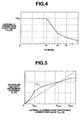
- the vehicular velocity controlling section 50 calculates the correction coefficient ⁇ Y G for the lateral acceleration Y G by referring to a correction coefficient calculation map shown in Fig. 4 on the basis of the read vehicular velocity Vs at the step S1. Then, the routine goes to a step S5.
- the correction coefficient calculation map has, as shown in Fig. 4, its lateral axis along which the vehicular velocity value Vs is taken and its longitudinal axis along which the correction coefficient ⁇ Y G to the lateral acceleration Y G is taken.
- the correction coefficient ⁇ Y G gives a first predetermined value ⁇ Y G1 .
- the correction coefficient ⁇ Y G is decreased by a relatively steep gradient in accordance with the increase in the vehicular velocity Vs.
- the correction coefficient ⁇ Y G is decreased at a relatively moderate gradient as compared with the gradient in the above-described vehicular velocity Vs.
- the vehicular velocity controlling section 50 determines whether the lateral acceleration corrected value Y GC calculated at the step S4 is equal to zero or positive or not (Y GC ⁇ 0 ).
- the vehicular velocity controlling section 50 refers to a calculation map on a vehicular velocity decrement variable V D shown in Fig. 5 to derive a vehicular velocity decrement variable V D and the routine goes to a step S9. If Y GC > 0 (No) at the step S6, the routine goes to a step S8. At the step S8, the vehicular velocity decrement variable V D is set to zero and the routine goes to the step S9.
- the vehicular velocity decrement variable calculation map has its lateral axis along which the lateral acceleration corrected value Y GC (G) is taken and its longitudinal axis along which the vehicular velocity decrement variable V D (G) is taken.
- the vehicular velocity decrement variable V D indicates zero when the lateral acceleration corrected value Y GC indicates zero.
- the vehicular velocity decrement variable V D is converted into a vehicular velocity correction variable Vc (Km/h) which is the variation rate of the vehicular velocity per unit time.
- the vehicular velocity controlling section 50 subtracts the vehicular velocity correction value Vc from a previous vehicular velocity command value V T (n-1) to derive a previously corrected vehicular velocity command value V REG .
- the vehicular velocity controlling section 50 compares the previously corrected vehicular velocity command value V REG with the selected target vehicular velocity V*. If V REG ⁇ V*s at the step S11, the routine goes to a step S12.
- a present vehicular velocity command value V T (n-1) is calculated by adding an acceleration set vehicular velocity ⁇ V A to the previously corrected vehicular velocity command value V REG and the routine goes to a step S15.
- V T (n) V REG .
- the vehicular velocity controlling section 50 controls the throttle valve opening angle via the throttle actuator 3, the gear position of the automatic transmission T and the braking force of the vehicular brake system B on the basis of the above-described present vehicular velocity command value V T (n).
- the step S3 and the lateral acceleration (G) sensor 4 correspond to vehicular turning magnitude detecting means, the step S4 corresponds to correction coefficient calculating means, the steps S5 to S10 correspond to target vehicular velocity correcting means.
- the vehicular velocity controlling section 50 sets one of the target vehicular velocity V* selected by the inter-vehicle distance controlling section 40 and the set vehicular velocity V SET by the vehicular driver which is smaller than the other as the selected target vehicular velocity Vs*, is increased by the vehicular set vehicular velocity V A when the present vehicular velocity command value V T (n) is smaller than the selected target vehicular velocity Vs*, and is decreased by the deceleration set vehicular velocity V D when the present vehicular velocity command value V T (n) is larger than the selected target vehicular velocity Vs*. Then, the vehicular velocity Vs is thus controlled in the way as described above to follow up the preceding vehicle.
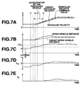
- the vehicle is running straightly on, for example, a city street maintaining the target inter-vehicle distance to the preceding vehicle which is running at a constant velocity (cruising) at a time point t0, as shown in Fig. 7A.
- the actual inter-vehicle distance L is made generally equal to the target inter-vehicle distance L* as shown in Fig. 7B.
- the preceding vehicle is running at the constant velocity and the inter-vehicle distance L T is made coincident with the actual inter-vehicle distance L.
- the vehicular velocity V* is made equal to the preceding vehicle.
- the vehicle is running straightly.
- the lateral acceleration Y G detected by the lateral acceleration sensor 4 maintains approximately zero as shown by Fig. 7C.
- the vehicular velocity Vs is in a low vehicular velocity region.
- the lateral acceleration Y GC calculated by the step S5 indicates - ⁇ Y G1 as shown in Fig. 7D.
- the routine goes from the step S6 to the step S8. Therefore, the routine goes from the step S6 to the step S8. Therefore, the vehicular velocity decrement variable V D is set to zero G as shown by Fig. 7E.
- the previous corrected vehicular velocity command value V REG calculated at the step S10 is made equal to the previous vehicular velocity command value V T (n -1). At this time, since the value of V REG is made equal to the pervious vehicular velocity command value V T (n -1). At this time, since the value of V REG is made equal to the target vehicular velocity V*, the routine goes to the step S11 to the step S13.
- the present vehicular velocity command value V T (n -1) is made equal to the previous vehicular velocity command value V T (n -1).
- the routine goes to the step S15.
- the throttle actuator 3 is controlled so that the opening angle of the throttle valve is adjusted to an angle such as to maintain the target vehicular velocity V* and the follow up run state at the cruise velocity is maintained.
- the vehicle is, at a time point t2 shown in Fig. 7A, about to enter the same cornering.
- the lateral acceleration Y G detected by the lateral acceleration sensor 4 is increased. Since the radius of curvature of the corner is large, the lateral acceleration YG is not so large.
- the correction coefficient ⁇ Y G gives the first predetermined value ⁇ Y G1 at the step S8 in Fig. 3.
- the lateral acceleration correction value Y GC continues to indicate a negative value.
- the vehicular velocity decrement variable V D continues to indicate the state of zero and the vehicle is continued to follow up the preceding vehicle at the target inter-vehicle distance L*.
- the preceding vehicle has passed, for example, about half the corner to run at an acceleration state. Accordingly, the actual inter-vehicle distance L detected by the inter-vehicle distance sensor 1 is increased by the target inter-vehicle distance L*, as denoted by a dot-and-dash line of Fig. 7A.
- the lateral acceleration corrected value Y GC continues to indicate a negative value.
- the vehicular velocity decrement variable V D maintains zero G. Since the target vehicular velocity V* is increased, the routine goes from the step S11 to the step S12.
- the acceleration set vehicular velocity ⁇ V A is added to the previous corrected vehicular velocity command value V T (n). Accordingly, the vehicular velocity Vs is increased at a time point t3 with a predetermined response delay.
- the lateral acceleration Y G is also increased which is detected by the lateral acceleration (G) sensor 4.
- the lateral acceleration sensor value Y G is slightly in excess of the correction coefficient ⁇ Y G as shown in Fig. 7D indicates a positive value.
- the routine goes from the step S6 to the step S7.
- the vehicular velocity decrement variable V D calculated by referring to Fig. 4 is increased from zero G.
- the vehicular velocity correction value Vc calculated is increased from 0 km/h.
- the previous corrected vehicular velocity command value V REG is decreased and the increase of the target vehicular velocity V* is continued. Therefore, the routine goes from the step S11 to the step S12.
- the acceleration set vehicular velocity ⁇ V A is added to the previous corrected vehicular velocity command value V REG .
- the increase of the present vehicular velocity command value V T (n) is slightly suppressed by the decrease in the previous corrected vehicular velocity command value V REG .
- the vehicular velocity correction value Vc is accordingly increased.
- the vehicular velocity correction value Vc is subtracted from the previous corrected vehicular velocity command value V REG . Therefore, the vehicular velocity command value V T is slightly reduced as compared with a case where no correction of the lateral acceleration is made so that the vehicular velocity is controlled so as to coincide with the vehicular velocity command value V T .
- the actual inter-vehicle distance L is controlled in a state slightly larger than the target inter-vehicle distance L* and the vehicle is accelerated to follow up the accelerating preceding vehicle.
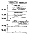
- the correction coefficient ⁇ Y G calculated at the step S8 in the inter-vehicle distance controlling section 40 in Fig. 3 becomes smaller by about one-fourth the correction coefficient at the relatively low vehicular velocity region.
- the lateral acceleration Y G detected by the lateral acceleration sensor 4 becomes large as compared with the acceleration sensor as shown in Fig. 8C.
- the correction coefficient value ⁇ Y G calculated at the step S8 in the inter-vehicle distance control procedure in Fig. 3 becomes smaller by about one-fourth the correction coefficient at the relatively low vehicular velocity region.
- the lateral acceleration Y G detected by the lateral acceleration sensor 4 becomes large as compared with a case of the low vehicular velocity region as shown in Fig. 8C.
- the lateral acceleration correction value Y GC indicates some positive value at a time point t1' immediately after the time point t1 shown in Fig. 8A. Accordingly, the vehicular velocity decrement variable V D is increased as shown in Fig. 8E.
- the previous corrected vehicular velocity command value V REG is quickly started to be decreased.
- an increase tendency of the vehicular velocity command value V T (n) becomes dull as compared with a case where no limitation on the lateral acceleration Y G denoted by a broken line shown in Fig. 8A.
- the target vehicular velocity V* is increased.
- the lateral acceleration correction (or corrected) value Y GC is accordingly increased.
- the vehicular velocity decrement variable V D is quickly increased. If the vehicular velocity decrement variable V D becomes equal to the acceleration corresponding to the acceleration set vehicular velocity ⁇ V A , the target vehicular velocity V* is accordingly increased. Then, the present vehicular velocity command value V T (n) becomes equal to the previous vehicular velocity command value V T (n - 1) so that the vehicular velocity is held.
- the lateral acceleration Y G is increased so that the vehicular velocity decrement variable V D is in excess of the acceleration corresponding to the acceleration set vehicular velocity ⁇ V A .
- the present vehicular velocity command value V T (n) calculated at the step S12 becomes smaller than the previous vehicular velocity command value V T (n - 1 ). Therefore, the vehicle is in the deceleration control state and the vehicular velocity Vs is decreased.
- the acceleration state of the vehicle when the vehicle is passing the corner at the relatively high vehicular velocity region is suppressed so that no mismatch to the driver's driving sense occurs and an optimum vehicular velocity control during the corner can be achieved.
- the lateral acceleration corrected value Y GC becomes accordingly small.
- the vehicular velocity decrement variable V D indicates the small value.
- the target vehicular velocity corrected value Vc* approaches to the target vehicular velocity Vc.
- the lateral acceleration corrected value Y GC indicates a negative value. Then, the vehicular velocity decrement variable value V D indicates zero.
- the target vehicular velocity correction value Vc* approaches to the target vehicular velocity Vc.
- the lateral acceleration corrected value Y GC indicates negative and the vehicular velocity decrement variable V D indicates zero.
- the target vehicular velocity V* is directly supplied to the vehicular velocity controlling section 50. Therefore, the vehicle is returned to the follow-up run state in which the actual inter-vehicle distance L is substantially made equal to the target inter-vehicle distance L* and the vehicle is returned to the follow-up run state.
- the set vehicular velocity V SET is set as the selected target vehicular velocity V*s to maintain the set vehicular velocity V SET .
- the lateral acceleration Y G detected by the lateral G sensor 4 is increased during the entrance of the corner.
- the vehicular velocity decrement variable V D in accordance with the lateral acceleration Y G and the vehicular velocity Vs is calculated. At this time, the vehicular velocity decrement variable V D in accordance with the lateral acceleration Y G and the vehicular velocity Vs is reduced.
- An optimum vehicular velocity control can, thus, be achieved without occurrence of the mismatch to the driver's driving sense.
- the correction coefficient ⁇ Y G of the lateral acceleration Y G is set according to the vehicular velocity Vs. Then, the lateral acceleration correction value Y GC is calculated. Since the vehicular velocity decrement variable V D based on the lateral acceleration corrected value Y GC is calculated, the vehicle is to follow up the preceding vehicle in a state near the target vehicular velocity V*.
- the vehicular velocity control in accordance with the driver's driving sense can be made when the vehicle is running at the corner at the relatively high velocity region. Giving the mismatch to the vehicular driver's driving sense can accurately be eliminated.
- the vehicular velocity controlling section 50 may determine if the vehicular velocity Vs is equal to or below the first predetermined vehicular velocity value V1. If Vs ⁇ V1, the correction coefficient ⁇ Y G may indicate the predetermined gradient ⁇ Y G1 . If Vs ⁇ V1, the correction coefficient ⁇ Y G may be calculated in accordance with the equation approximated to the characteristic line of Fig. 4. Alternatively, if Vs ⁇ 0, the correction coefficient ⁇ Y G may indicate the predetermined value of ⁇ Y G1 or may linearly be decreased in accordance with the increase in the vehicular velocity Vs.
- the correction coefficient may linearly be decreased.
- a straight line approximation as denoted by a broken line in Fig. 5 may be performed.
- the vehicular velocity decrement variable V D may be calculated.
- the lateral acceleration sensor 4 is applied as the turning magnitude detecting means, a yaw rate (yaw angular velocity) sensor may be applied in place of the lateral G sensor.
- a steering angle sensor to detect a steering angular displacement of a vehicular steering system may be applied in place of the lateral acceleration sensor.
- the detected steering angular displacement ⁇ of a vehicular steering system may be applied in place of the lateral acceleration sensor.
- the detected steering angular displacement ⁇ may be used to calculate the lateral acceleration Y G using the following equation (5).
- the vehicular running condition during the turning on the curved road (during the cornering) may be detected.
- Y G Vs 2 x ⁇ /(SF x Vs 2 + 1)x Lw x Gs
- SF denotes a stability factor
- Lw denotes a wheel base
- Gs denotes a steering gear ratio
- the correction coefficient ⁇ Y G according to the vehicular velocity Vs by the vehicular velocity controlling section 50 is used to correct the lateral acceleration Y G to derive the lateral acceleration correction value Y GC .
- the vehicular velocity decrement variable V D is, then, calculated on the basis of the lateral acceleration correction value Y GC and, then, is used to derive the vehicular velocity command value V T .
- the target vehicular velocity V* calculated by the inter-vehicle distance controlling section 40 may be decremented by the vehicular velocity corrected value Vc which accords with the vehicular velocity decrement variable value V D to calculate the corrected value Vc to calculate a corrected target vehicular velocity Vc* and the vehicular velocity controlling section may control the vehicular velocity Vs to make the vehicular velocity Vs substantially equal to the corrected target vehicular velocity Vc.
- the target inter-vehicle distance L* is calculated on the basis of the vehicular velocity Vt of the preceding vehicle.
- the vehicular velocity Vs of the vehicle C may be applied in place of the vehicular velocity of the preceding vehicle Vt.
- the follow-up run controller 5 executes the inter-vehicle distance calculating procedure
- a hardware of an electronic circuitry such as a combination of function generators, comparators, and arithmetic/logic unit may be applied.
- the present invention is applicable to the rear wheel drive vehicle as shown in Fig. 1A.
- the present invention may alternatively be applied to a front wheel drive vehicle.
- the present invention may be applied to an electric motor vehicle whose driving source is the electric motor or to a hybrid vehicle whose driving source is the electric motor or the engine.
Landscapes
- Engineering & Computer Science (AREA)
- Transportation (AREA)
- Mechanical Engineering (AREA)
- Chemical & Material Sciences (AREA)
- Combustion & Propulsion (AREA)
- Automation & Control Theory (AREA)
- Controls For Constant Speed Travelling (AREA)
- Control Of Driving Devices And Active Controlling Of Vehicle (AREA)
- Control Of Vehicle Engines Or Engines For Specific Uses (AREA)
Applications Claiming Priority (2)
| Application Number | Priority Date | Filing Date | Title |
|---|---|---|---|
| JP16826299A JP3960406B2 (ja) | 1999-06-15 | 1999-06-15 | 先行車追従制御装置 |
| JP16826299 | 1999-06-15 |
Publications (3)
| Publication Number | Publication Date |
|---|---|
| EP1060937A2 true EP1060937A2 (de) | 2000-12-20 |
| EP1060937A3 EP1060937A3 (de) | 2001-09-12 |
| EP1060937B1 EP1060937B1 (de) | 2006-09-13 |
Family
ID=15864760
Family Applications (1)
| Application Number | Title | Priority Date | Filing Date |
|---|---|---|---|
| EP00304976A Expired - Lifetime EP1060937B1 (de) | 1999-06-15 | 2000-06-13 | Abstandsbezogene Fahrgeschwindigkeitsregelung bei Kurvenfahrt |
Country Status (4)
| Country | Link |
|---|---|
| US (1) | US6298298B1 (de) |
| EP (1) | EP1060937B1 (de) |
| JP (1) | JP3960406B2 (de) |
| DE (1) | DE60030626T2 (de) |
Cited By (3)
| Publication number | Priority date | Publication date | Assignee | Title |
|---|---|---|---|---|
| WO2001079013A1 (de) * | 2000-04-14 | 2001-10-25 | Robert Bosch Gmbh | Abstandsbezogenes verfahren zur regelung der geschwindigkeit eines fahrzeugs |
| EP1225079A3 (de) * | 2001-01-19 | 2004-06-30 | Nissan Motor Company, Limited | Abstandsbezogenes, adaptives Fahrgeschwindigkeitsregelsystem |
| FR2912981A1 (fr) * | 2007-02-22 | 2008-08-29 | Peugeot Citroen Automobiles Sa | Procede de pilotage automatique de vehicule automobile comprenant un systeme acc |
Families Citing this family (11)
| Publication number | Priority date | Publication date | Assignee | Title |
|---|---|---|---|---|
| JP3661496B2 (ja) * | 1999-06-15 | 2005-06-15 | 日産自動車株式会社 | 先行車追従制御装置 |
| JP3608433B2 (ja) | 1999-06-15 | 2005-01-12 | 日産自動車株式会社 | 先行車追従制御装置 |
| DE10006403B4 (de) * | 2000-02-12 | 2015-07-09 | Volkswagen Ag | Verfahren zur Geschwindigkeits- und Abstandsregelung eines Kraftfahrzeuges |
| US6671607B2 (en) * | 2000-05-16 | 2003-12-30 | Nissan Motor Co., Ltd. | Vehicle speed control system |
| DE10159658A1 (de) * | 2001-12-05 | 2003-06-26 | Daimler Chrysler Ag | System zur automatischen Folgeführung eines Kraftfahrzeugs |
| US7272482B2 (en) * | 2002-09-30 | 2007-09-18 | Nissan Motor Co., Ltd. | Preceding-vehicle following control system |
| JP2005231491A (ja) * | 2004-02-19 | 2005-09-02 | Honda Motor Co Ltd | 追従走行制御装置 |
| JP5066437B2 (ja) * | 2007-12-21 | 2012-11-07 | 富士重工業株式会社 | 車両の走行制御装置 |
| US8738319B2 (en) * | 2010-10-29 | 2014-05-27 | Ford Global Technologies, Llc | System and method for detecting a turning vehicle |
| KR101535019B1 (ko) * | 2014-05-02 | 2015-07-07 | 현대자동차주식회사 | 차량의 횡가속도 오프셋 보정 장치 및 방법 |
| CN111717212B (zh) * | 2019-03-18 | 2022-03-04 | 毫末智行科技有限公司 | 自动驾驶车辆的跟随控制方法及装置 |
Citations (2)
| Publication number | Priority date | Publication date | Assignee | Title |
|---|---|---|---|---|
| JPH0747864A (ja) | 1993-06-15 | 1995-02-21 | Nissan Motor Co Ltd | 車間距離制御装置 |
| JPH11168262A (ja) | 1997-09-30 | 1999-06-22 | Canon Inc | 面型光デバイス、その製造方法、および表示装置 |
Family Cites Families (8)
| Publication number | Priority date | Publication date | Assignee | Title |
|---|---|---|---|---|
| JPS61278775A (ja) * | 1985-06-03 | 1986-12-09 | Nissan Motor Co Ltd | 先行車検出装置 |
| US5161632A (en) * | 1990-06-01 | 1992-11-10 | Mitsubishi Denki K.K. | Tracking control device for a vehicle |
| JP3164439B2 (ja) * | 1992-10-21 | 2001-05-08 | マツダ株式会社 | 車両用障害物検出装置 |
| IT1261151B (it) * | 1993-12-30 | 1996-05-09 | Fiat Ricerche | Sistema di controllo automatico della velocita' di un veicolo |
| GB9606384D0 (en) * | 1996-03-26 | 1996-06-05 | Jaguar Cars | Cruise control systems |
| JPH11278096A (ja) * | 1998-03-30 | 1999-10-12 | Nissan Motor Co Ltd | 車両用走行制御装置 |
| JP3651259B2 (ja) | 1998-05-01 | 2005-05-25 | 日産自動車株式会社 | 先行車追従制御装置 |
| JP3509654B2 (ja) * | 1999-08-31 | 2004-03-22 | トヨタ自動車株式会社 | 車輌の制御装置 |
-
1999
- 1999-06-15 JP JP16826299A patent/JP3960406B2/ja not_active Expired - Fee Related
-
2000
- 2000-06-12 US US09/592,565 patent/US6298298B1/en not_active Expired - Lifetime
- 2000-06-13 DE DE60030626T patent/DE60030626T2/de not_active Expired - Lifetime
- 2000-06-13 EP EP00304976A patent/EP1060937B1/de not_active Expired - Lifetime
Patent Citations (2)
| Publication number | Priority date | Publication date | Assignee | Title |
|---|---|---|---|---|
| JPH0747864A (ja) | 1993-06-15 | 1995-02-21 | Nissan Motor Co Ltd | 車間距離制御装置 |
| JPH11168262A (ja) | 1997-09-30 | 1999-06-22 | Canon Inc | 面型光デバイス、その製造方法、および表示装置 |
Cited By (4)
| Publication number | Priority date | Publication date | Assignee | Title |
|---|---|---|---|---|
| WO2001079013A1 (de) * | 2000-04-14 | 2001-10-25 | Robert Bosch Gmbh | Abstandsbezogenes verfahren zur regelung der geschwindigkeit eines fahrzeugs |
| US6721645B2 (en) | 2000-04-14 | 2004-04-13 | Robert Bosch Gmbh | Distance-related method for controlling the speed of a vehicle |
| EP1225079A3 (de) * | 2001-01-19 | 2004-06-30 | Nissan Motor Company, Limited | Abstandsbezogenes, adaptives Fahrgeschwindigkeitsregelsystem |
| FR2912981A1 (fr) * | 2007-02-22 | 2008-08-29 | Peugeot Citroen Automobiles Sa | Procede de pilotage automatique de vehicule automobile comprenant un systeme acc |
Also Published As
| Publication number | Publication date |
|---|---|
| JP2000355231A (ja) | 2000-12-26 |
| DE60030626D1 (de) | 2006-10-26 |
| JP3960406B2 (ja) | 2007-08-15 |
| DE60030626T2 (de) | 2007-10-04 |
| EP1060937A3 (de) | 2001-09-12 |
| EP1060937B1 (de) | 2006-09-13 |
| US6298298B1 (en) | 2001-10-02 |
Similar Documents
| Publication | Publication Date | Title |
|---|---|---|
| US6401024B1 (en) | Vehicle follow-up control system | |
| US6405120B1 (en) | Vehicular velocity controlling apparatus and method to follow up a preceding vehicle running ahead of vehicle | |
| EP1060940B1 (de) | Abstandsbezogenes Fahrgeschwindigkeitsregelsystem | |
| EP1061495B1 (de) | Vorrichtung und Verfahren zur Geschwindigkeits-und-Abstandsreglung eines Fahrzeugs | |
| EP0949108B1 (de) | Abstandsbezogenes Fahrgeschwindigkeitsregelsystem | |
| US6298298B1 (en) | Vehicular velocity controlling apparatus and method to follow up a preceding vehicle running ahead of vehicle | |
| US6233516B1 (en) | Apparatus and method for controlling inter-vehicle distance to another vehicle traveling ahead of automotive vehicle equipped with the apparatus and method | |
| US6430494B1 (en) | Preceding vehicle following control apparatus and method for automotive vehicle | |
| EP1486370B1 (de) | Abstandsbezogenes Fahrgeschwindigkeitsregelsystem | |
| JP3651259B2 (ja) | 先行車追従制御装置 | |
| US7054733B2 (en) | Adaptive cruise control system for vehicle | |
| US6678603B2 (en) | Vehicular adaptive cruise control apparatus and method with preceding vehicle following control function | |
| EP1055542B1 (de) | Abstandsbezogenes Fahrgeschwindigkeitsregelsystem mit Gewinnregelung | |
| US20020173896A1 (en) | System and method for controlling vehicle velocity and inter-vehicle distance | |
| JPH0676025B2 (ja) | 自動車の推進調整方法及び装置 | |
| CN113022565A (zh) | 车辆控制装置 | |
| JP3204121B2 (ja) | 車両用前後加速度推定装置 | |
| US6870468B2 (en) | Adaptive cruise speed controlling apparatus and method for automotive vehicle | |
| US20020111733A1 (en) | Vehicle vilocity control apparatus and method with preceding vehicle following control function | |
| JP2001027317A (ja) | 自動走行制御装置及び記録媒体 | |
| JP3658773B2 (ja) | 車両の速度制御装置 | |
| US20220089221A1 (en) | Determining a steering reference state by means of wheel speed values | |
| JP4919850B2 (ja) | 車載用レーダ装置 | |
| JP3811296B2 (ja) | 自動車の走行制御装置 | |
| JP2001082201A (ja) | 車輌の挙動制御装置 |
Legal Events
| Date | Code | Title | Description |
|---|---|---|---|
| PUAI | Public reference made under article 153(3) epc to a published international application that has entered the european phase |
Free format text: ORIGINAL CODE: 0009012 |
|
| 17P | Request for examination filed |
Effective date: 20000712 |
|
| AK | Designated contracting states |
Kind code of ref document: A2 Designated state(s): DE FR GB Kind code of ref document: A2 Designated state(s): AT BE CH CY DE DK ES FI FR GB GR IE IT LI LU MC NL PT SE |
|
| AX | Request for extension of the european patent |
Free format text: AL;LT;LV;MK;RO;SI |
|
| PUAL | Search report despatched |
Free format text: ORIGINAL CODE: 0009013 |
|
| AK | Designated contracting states |
Kind code of ref document: A3 Designated state(s): AT BE CH CY DE DK ES FI FR GB GR IE IT LI LU MC NL PT SE |
|
| AX | Request for extension of the european patent |
Free format text: AL;LT;LV;MK;RO;SI |
|
| RIC1 | Information provided on ipc code assigned before grant |
Free format text: 7B 60K 31/00 A, 7G 01S 13/93 B |
|
| AKX | Designation fees paid |
Free format text: DE FR GB |
|
| GRAP | Despatch of communication of intention to grant a patent |
Free format text: ORIGINAL CODE: EPIDOSNIGR1 |
|
| RIC1 | Information provided on ipc code assigned before grant |
Ipc: G01S 13/93 20060101ALI20060202BHEP Ipc: B60W 30/16 20060101AFI20060202BHEP |
|
| GRAS | Grant fee paid |
Free format text: ORIGINAL CODE: EPIDOSNIGR3 |
|
| GRAA | (expected) grant |
Free format text: ORIGINAL CODE: 0009210 |
|
| RAP1 | Party data changed (applicant data changed or rights of an application transferred) |
Owner name: NISSAN MOTOR COMPANY LIMITED |
|
| AK | Designated contracting states |
Kind code of ref document: B1 Designated state(s): DE FR GB |
|
| REG | Reference to a national code |
Ref country code: GB Ref legal event code: FG4D |
|
| REF | Corresponds to: |
Ref document number: 60030626 Country of ref document: DE Date of ref document: 20061026 Kind code of ref document: P |
|
| ET | Fr: translation filed | ||
| PLBE | No opposition filed within time limit |
Free format text: ORIGINAL CODE: 0009261 |
|
| STAA | Information on the status of an ep patent application or granted ep patent |
Free format text: STATUS: NO OPPOSITION FILED WITHIN TIME LIMIT |
|
| 26N | No opposition filed |
Effective date: 20070614 |
|
| REG | Reference to a national code |
Ref country code: FR Ref legal event code: PLFP Year of fee payment: 17 |
|
| REG | Reference to a national code |
Ref country code: FR Ref legal event code: PLFP Year of fee payment: 18 |
|
| REG | Reference to a national code |
Ref country code: FR Ref legal event code: PLFP Year of fee payment: 19 |
|
| PGFP | Annual fee paid to national office [announced via postgrant information from national office to epo] |
Ref country code: DE Payment date: 20190528 Year of fee payment: 20 |
|
| PGFP | Annual fee paid to national office [announced via postgrant information from national office to epo] |
Ref country code: FR Payment date: 20190510 Year of fee payment: 20 |
|
| PGFP | Annual fee paid to national office [announced via postgrant information from national office to epo] |
Ref country code: GB Payment date: 20190612 Year of fee payment: 20 |
|
| REG | Reference to a national code |
Ref country code: DE Ref legal event code: R071 Ref document number: 60030626 Country of ref document: DE |
|
| REG | Reference to a national code |
Ref country code: GB Ref legal event code: PE20 Expiry date: 20200612 |
|
| PG25 | Lapsed in a contracting state [announced via postgrant information from national office to epo] |
Ref country code: GB Free format text: LAPSE BECAUSE OF EXPIRATION OF PROTECTION Effective date: 20200612 |