EP1060941A2 - Dispositif de contrôle et de fonctionnement de la traction d'un véhicule électrique - Google Patents
Dispositif de contrôle et de fonctionnement de la traction d'un véhicule électrique Download PDFInfo
- Publication number
- EP1060941A2 EP1060941A2 EP00110396A EP00110396A EP1060941A2 EP 1060941 A2 EP1060941 A2 EP 1060941A2 EP 00110396 A EP00110396 A EP 00110396A EP 00110396 A EP00110396 A EP 00110396A EP 1060941 A2 EP1060941 A2 EP 1060941A2
- Authority
- EP
- European Patent Office
- Prior art keywords
- sub
- motors
- power
- units
- motor
- Prior art date
- Legal status (The legal status is an assumption and is not a legal conclusion. Google has not performed a legal analysis and makes no representation as to the accuracy of the status listed.)
- Granted
Links
- 101100446506 Mus musculus Fgf3 gene Proteins 0.000 abstract 1
- 238000012544 monitoring process Methods 0.000 description 5
- 238000010586 diagram Methods 0.000 description 2
- 230000004913 activation Effects 0.000 description 1
- 230000005540 biological transmission Effects 0.000 description 1
- 230000007257 malfunction Effects 0.000 description 1
- 230000001960 triggered effect Effects 0.000 description 1
Images


Classifications
-
- B—PERFORMING OPERATIONS; TRANSPORTING
- B60—VEHICLES IN GENERAL
- B60L—PROPULSION OF ELECTRICALLY-PROPELLED VEHICLES; SUPPLYING ELECTRIC POWER FOR AUXILIARY EQUIPMENT OF ELECTRICALLY-PROPELLED VEHICLES; ELECTRODYNAMIC BRAKE SYSTEMS FOR VEHICLES IN GENERAL; MAGNETIC SUSPENSION OR LEVITATION FOR VEHICLES; MONITORING OPERATING VARIABLES OF ELECTRICALLY-PROPELLED VEHICLES; ELECTRIC SAFETY DEVICES FOR ELECTRICALLY-PROPELLED VEHICLES
- B60L3/00—Electric devices on electrically-propelled vehicles for safety purposes; Monitoring operating variables, e.g. speed, deceleration or energy consumption
- B60L3/0023—Detecting, eliminating, remedying or compensating for drive train abnormalities, e.g. failures within the drive train
-
- Y—GENERAL TAGGING OF NEW TECHNOLOGICAL DEVELOPMENTS; GENERAL TAGGING OF CROSS-SECTIONAL TECHNOLOGIES SPANNING OVER SEVERAL SECTIONS OF THE IPC; TECHNICAL SUBJECTS COVERED BY FORMER USPC CROSS-REFERENCE ART COLLECTIONS [XRACs] AND DIGESTS
- Y02—TECHNOLOGIES OR APPLICATIONS FOR MITIGATION OR ADAPTATION AGAINST CLIMATE CHANGE
- Y02T—CLIMATE CHANGE MITIGATION TECHNOLOGIES RELATED TO TRANSPORTATION
- Y02T10/00—Road transport of goods or passengers
- Y02T10/60—Other road transportation technologies with climate change mitigation effect
- Y02T10/64—Electric machine technologies in electromobility
Definitions
- the invention relates to a device for the control and Operation of an electric vehicle drive, according to the features the preamble of claim 1.
- Redundant control systems are a further development stage known and two-circuit electric motors (see Figure 2), the starting of control devices.
- (11, 12) which are the control signals for driving, braking, steering (2) and bus lines (31, 32) to the chain drives left and right (4, 5) pass on the drive motors (41, 51) via assigned power units (42, 52) and control and supply lines (43, 44, 45, 46, 53, 54, 55, 56) for the desired driving condition
- Control driving, braking, steering but as a specialty the motors on each side in two sub-motors (411, 412 or 511, 512) and the associated power units are also divided into assigned sub-units (421, 422 and 521, 522, respectively).
- a simple error case e.g.
- the object of the invention is the safe and fast shutdown or partial shutdown and influencing the symmetrical component one chain side of the drive if one component fails on the other side of the chain (see Figure 3).
- the invention proposes to interconnect the drive sides with their power units and sub-motors so that immediate monitoring and switching off from one side to the other and vice versa is provided.
- the power units (42, 52, see FIG. 3) for controlling the sub-motors are each divided into two sub-units (421, 422 and 521, 522) and the drive motors (41, 51) accordingly also into two sub-motors (411, 412 and 511 , 512).
- a power unit is connected to a sub-unit (422) with the opposite sub-motor (512) for control.
- the other sub-unit (421) of the power unit is connected to the corresponding sub-motor (411) on the same side as the power unit. Accordingly, the power unit on the other side is connected to the sub-motors on the left and right. With each power unit, half of the left and right drive motors are each controlled with a sub-motor.
- the sub-motor (511) also fails and the neighboring power unit (522) is also immediately switched off or readjusted and with it the associated sub-motor (412) on the other side, so that the vehicle continues to drive straight ahead Can drive at a possibly reduced speed.
- the division of the drive motor and the assigned power unit can also be further increased and configured differently, for example by dividing it into 3 motor modules and then 3 assigned power unit units. To maintain a correspondingly high availability of the power units, these are supplied from separate power supplies (6, 7) with respect to the control.
- the power units for the power supply for the drive motors to be controlled are likewise supplied from separate generator circuits (8, 9). It is also possible to use more than one generator on one or more diesel engines for feeding the travel circuits.
- the high security is advantageous in the solution according to the invention when driving, which is the unpredictable wrong reaction of a vehicle in the event of failure of an electrical drive component avoids or to an uncritical minimum by reduction the drive power and so the driver in able to continue to control the vehicle safely. This makes it possible to meet the high security requirements to meet in public road traffic and approval to reach an electric tracked vehicle.
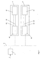
- Figure 1 illustrates an electric drive for a tracked vehicle with a control device (1) which controls the control signals for driving, braking, steering (2) and via a bus line (3) to the chain drives on the left and right (4, 5) and the drive motors (41, 51) via assigned power units (42, 52) and control and supply lines (43, 44, 53, 54) for the desired driving state driving, braking, Steering controls.
- a control device (1) which controls the control signals for driving, braking, steering (2) and via a bus line (3) to the chain drives on the left and right (4, 5) and the drive motors (41, 51) via assigned power units (42, 52) and control and supply lines (43, 44, 53, 54) for the desired driving state driving, braking, Steering controls.
- Figure 3 shows the inventive design of an electric drive for a tracked vehicle with known control devices (11, 12, 13), which are controlled by operating signals (2), and signal bus lines (31, 32) and power units (42, 52) for Activation of the sub-motors are divided into two sub-units (421, 422 and 521, 522), and drive motors (41, 51), which are also divided into two sub-motors (411, 412 and 511, 512).
- a power unit is connected to a sub-unit (422) with the opposite sub-motor (512) for control.
- the other sub-unit (421) of the power unit is connected to the corresponding sub-motor (411) on the same side as the power unit.
- the power unit on the other side is connected to the sub-motors on the left and right.
- half of the left and right drive motors are each controlled with a sub-motor.
- the power units are each supplied with separate batteries (6, 7) for the control.
- the power units from separate generator circuits (8, 9) are also supplied with power for the drive motors.
Landscapes
- Engineering & Computer Science (AREA)
- Life Sciences & Earth Sciences (AREA)
- Sustainable Development (AREA)
- Sustainable Energy (AREA)
- Power Engineering (AREA)
- Transportation (AREA)
- Mechanical Engineering (AREA)
- Electric Propulsion And Braking For Vehicles (AREA)
- Power Steering Mechanism (AREA)
- Hybrid Electric Vehicles (AREA)
- Arrangement Or Mounting Of Propulsion Units For Vehicles (AREA)
- Control Of Multiple Motors (AREA)
Applications Claiming Priority (2)
| Application Number | Priority Date | Filing Date | Title |
|---|---|---|---|
| DE19927848A DE19927848B4 (de) | 1999-06-18 | 1999-06-18 | Einrichtung für die Ansteuerung und Betrieb eines elektrischen Fahrzeugantriebes |
| DE19927848 | 1999-06-18 |
Publications (3)
| Publication Number | Publication Date |
|---|---|
| EP1060941A2 true EP1060941A2 (fr) | 2000-12-20 |
| EP1060941A3 EP1060941A3 (fr) | 2002-07-10 |
| EP1060941B1 EP1060941B1 (fr) | 2003-10-01 |
Family
ID=7911686
Family Applications (1)
| Application Number | Title | Priority Date | Filing Date |
|---|---|---|---|
| EP00110396A Expired - Lifetime EP1060941B1 (fr) | 1999-06-18 | 2000-05-16 | Dispositif de contrôle et de fonctionnement de la traction d'un véhicule électrique |
Country Status (2)
| Country | Link |
|---|---|
| EP (1) | EP1060941B1 (fr) |
| DE (2) | DE19927848B4 (fr) |
Cited By (4)
| Publication number | Priority date | Publication date | Assignee | Title |
|---|---|---|---|---|
| WO2005054041A1 (fr) * | 2003-12-04 | 2005-06-16 | Renk Aktiengesellschaft | Systeme de direction et d'entrainement electrique pour un vehicule a direction laterale des roues |
| EP1847416A1 (fr) * | 2006-04-22 | 2007-10-24 | ZF Friedrichshafen AG | Dispositif et procédé destinés à la commande d'un véhicule doté de plusieurs modules d'axes |
| US7616443B2 (en) | 2003-12-05 | 2009-11-10 | Renk Aktiengesellschaft | Cooling device for electrical power units of electrically operated vehicles |
| EP1912846B2 (fr) † | 2005-08-01 | 2014-05-21 | Knorr-Bremse Gesellschaft mit beschränkter Haftung | Procede et dispositif pour mettre hors service des portes defectueuses |
Families Citing this family (2)
| Publication number | Priority date | Publication date | Assignee | Title |
|---|---|---|---|---|
| CN105739305A (zh) * | 2016-01-29 | 2016-07-06 | 北京理工大学 | 一种履带车辆的控制方法 |
| DE102016121672A1 (de) | 2016-11-11 | 2018-05-17 | Rheinmetall Landsysteme Gmbh | Antrieb für Fahrzeuge insbesondere Gefechtsfahrzeuge |
Citations (1)
| Publication number | Priority date | Publication date | Assignee | Title |
|---|---|---|---|---|
| DE19732764A1 (de) | 1997-07-30 | 1999-02-04 | Mak System Gmbh | Übertragungseinrichtung für Steuersignale, insbesondere in Fahrzeugen |
Family Cites Families (6)
| Publication number | Priority date | Publication date | Assignee | Title |
|---|---|---|---|---|
| US4554989A (en) * | 1983-01-20 | 1985-11-26 | Peter Gruich | Multimotor modular electric drive powertrain system for turbine powered vehicles |
| DE4011291A1 (de) * | 1990-04-06 | 1991-10-17 | Magnet Motor Gmbh | Elektrofahrzeug mit einzeln gesteuerten antriebs-elektromotoren |
| DE4311230C2 (de) * | 1993-04-02 | 1996-12-19 | Mannesmann Ag | Nicht-spurgebundenes Fahrzeug mit Elektromotor |
| DE19537945C2 (de) * | 1995-10-12 | 2000-07-20 | Mak System Gmbh | Kettenfahrzeug |
| DE19624090C1 (de) * | 1996-06-17 | 1997-10-02 | Siemens Ag | Einspeiseschaltung für eine Mehrsystem-Traktionseinrichtung |
| DE19756683C1 (de) * | 1997-12-19 | 1999-06-02 | Mak System Gmbh | Fahrantrieb für Kettenfahrzeuge |
-
1999
- 1999-06-18 DE DE19927848A patent/DE19927848B4/de not_active Expired - Fee Related
-
2000
- 2000-05-16 DE DE50003879T patent/DE50003879D1/de not_active Expired - Lifetime
- 2000-05-16 EP EP00110396A patent/EP1060941B1/fr not_active Expired - Lifetime
Patent Citations (1)
| Publication number | Priority date | Publication date | Assignee | Title |
|---|---|---|---|---|
| DE19732764A1 (de) | 1997-07-30 | 1999-02-04 | Mak System Gmbh | Übertragungseinrichtung für Steuersignale, insbesondere in Fahrzeugen |
Cited By (5)
| Publication number | Priority date | Publication date | Assignee | Title |
|---|---|---|---|---|
| WO2005054041A1 (fr) * | 2003-12-04 | 2005-06-16 | Renk Aktiengesellschaft | Systeme de direction et d'entrainement electrique pour un vehicule a direction laterale des roues |
| US8813879B2 (en) | 2003-12-04 | 2014-08-26 | Renk Aktiengesellschaft | Electric steering and driving system for a lateral wheel-steering vehicle |
| US7616443B2 (en) | 2003-12-05 | 2009-11-10 | Renk Aktiengesellschaft | Cooling device for electrical power units of electrically operated vehicles |
| EP1912846B2 (fr) † | 2005-08-01 | 2014-05-21 | Knorr-Bremse Gesellschaft mit beschränkter Haftung | Procede et dispositif pour mettre hors service des portes defectueuses |
| EP1847416A1 (fr) * | 2006-04-22 | 2007-10-24 | ZF Friedrichshafen AG | Dispositif et procédé destinés à la commande d'un véhicule doté de plusieurs modules d'axes |
Also Published As
| Publication number | Publication date |
|---|---|
| EP1060941B1 (fr) | 2003-10-01 |
| DE19927848A1 (de) | 2001-01-11 |
| EP1060941A3 (fr) | 2002-07-10 |
| DE19927848B4 (de) | 2004-09-16 |
| DE50003879D1 (de) | 2003-11-06 |
Similar Documents
| Publication | Publication Date | Title |
|---|---|---|
| DE102009013398B4 (de) | Verfahren zur Unterbrechung des Kraftflusses im Antriebsstrang eines Fahrzeuges im Crashfall | |
| DE102012112912A1 (de) | Leistungszuführungssystem für Fahrzeuge | |
| EP0780276A2 (fr) | Dispositif de freinage pour un véhicule | |
| DE102007036259A1 (de) | Bremssystem für ein Fahrzeug und ein Verfahren zum Betreiben eines Bremssystems für ein Fahrzeug | |
| EP3670277B1 (fr) | Système de freinage pour véhicule automobile et véhicule automobile doté d'un tel système de freinage | |
| EP2450214B1 (fr) | Dameur de piste | |
| WO2005082694A1 (fr) | Systeme de commande de freinage redondant pour un vehicule | |
| EP1052148A2 (fr) | Réseau de bord de véhicule | |
| DE102010035149B4 (de) | Sicherheitsschaltung für einen Elektromotor einer elektromechanischen Lenkung | |
| DE102017104667A1 (de) | Stromversorgungseinheit für ein Nutzfahrzeug und Verfahren zum Betreiben einer Stromversorgungseinheit für ein Nutzfahrzeug | |
| EP1723026A1 (fr) | Systeme de direction et d'entrainement electrique pour un vehicule a baquage des roues | |
| EP4377170B1 (fr) | Système de freinage électromécanique redondant et son actionneur | |
| DE102015012944B4 (de) | Betrieb einer Kraftfahrzeugkomponente bei Ausfall eines puffernden Energiespeichers | |
| EP2072374A2 (fr) | Procédé et dispositif destinés à l'amortissement d'une direction d'axe arrière | |
| DE102020202466B4 (de) | Redundantes Bordnetzsystem und Kraftfahrzeug | |
| EP1060941B1 (fr) | Dispositif de contrôle et de fonctionnement de la traction d'un véhicule électrique | |
| WO2018104044A1 (fr) | Véhicule hybride | |
| EP1134145A2 (fr) | Dispositif de protection pour un système de direction électrique | |
| WO2014023375A1 (fr) | Véhicule automobile équipé d'une alimentation à basse tension de grande sécurité | |
| DE102017216635A1 (de) | Fahrzeug mit elektrischer Antriebseinrichtung, insbesondere für autonomes Fahren | |
| EP1052760A2 (fr) | Système d'un CAN-bus avec des sous-réseaux déconnectables automatiquement pendant des pannes | |
| DE102010017863A1 (de) | Verfahren zur Fehlererkennung in einem Hybridantriebsstrang | |
| DE102007036260A1 (de) | Elektrisches Bremssystem | |
| DE102023202881A1 (de) | Verfahren zum Betreiben eines Lenksystems, Lenksystem und Fahrzeug | |
| DE10122954B4 (de) | Verfahren und Schaltungsanordnung zur Strom- und Spannungsversorgung von mindestens einem elektrischen Verbraucher in einem Kraftfahrzeug und deren Verwendung in einem elektrischen Bremssystem |
Legal Events
| Date | Code | Title | Description |
|---|---|---|---|
| PUAI | Public reference made under article 153(3) epc to a published international application that has entered the european phase |
Free format text: ORIGINAL CODE: 0009012 |
|
| AK | Designated contracting states |
Kind code of ref document: A2 Designated state(s): AT BE CH CY DE DK ES FI FR GB GR IE IT LI LU MC NL PT SE |
|
| AX | Request for extension of the european patent |
Free format text: AL;LT;LV;MK;RO;SI |
|
| RAP1 | Party data changed (applicant data changed or rights of an application transferred) |
Owner name: RHEINMETALL LANDSYSTEME GMBH Owner name: MAGNET-MOTOR GMBH |
|
| PUAL | Search report despatched |
Free format text: ORIGINAL CODE: 0009013 |
|
| AK | Designated contracting states |
Kind code of ref document: A3 Designated state(s): AT BE CH CY DE DK ES FI FR GB GR IE IT LI LU MC NL PT SE |
|
| AX | Request for extension of the european patent |
Free format text: AL;LT;LV;MK;RO;SI |
|
| 17P | Request for examination filed |
Effective date: 20020606 |
|
| AKX | Designation fees paid |
Designated state(s): DE FR GB SE |
|
| GRAH | Despatch of communication of intention to grant a patent |
Free format text: ORIGINAL CODE: EPIDOS IGRA |
|
| GRAH | Despatch of communication of intention to grant a patent |
Free format text: ORIGINAL CODE: EPIDOS IGRA |
|
| GRAA | (expected) grant |
Free format text: ORIGINAL CODE: 0009210 |
|
| AK | Designated contracting states |
Kind code of ref document: B1 Designated state(s): DE FR GB SE |
|
| REG | Reference to a national code |
Ref country code: GB Ref legal event code: FG4D Free format text: NOT ENGLISH |
|
| REG | Reference to a national code |
Ref country code: IE Ref legal event code: FG4D Free format text: GERMAN |
|
| REF | Corresponds to: |
Ref document number: 50003879 Country of ref document: DE Date of ref document: 20031106 Kind code of ref document: P |
|
| REG | Reference to a national code |
Ref country code: SE Ref legal event code: TRGR |
|
| GBT | Gb: translation of ep patent filed (gb section 77(6)(a)/1977) |
Effective date: 20031224 |
|
| REG | Reference to a national code |
Ref country code: IE Ref legal event code: FD4D |
|
| ET | Fr: translation filed | ||
| PLBE | No opposition filed within time limit |
Free format text: ORIGINAL CODE: 0009261 |
|
| STAA | Information on the status of an ep patent application or granted ep patent |
Free format text: STATUS: NO OPPOSITION FILED WITHIN TIME LIMIT |
|
| 26N | No opposition filed |
Effective date: 20040702 |
|
| PGFP | Annual fee paid to national office [announced via postgrant information from national office to epo] |
Ref country code: SE Payment date: 20060512 Year of fee payment: 7 |
|
| PGFP | Annual fee paid to national office [announced via postgrant information from national office to epo] |
Ref country code: GB Payment date: 20060522 Year of fee payment: 7 |
|
| EUG | Se: european patent has lapsed | ||
| GBPC | Gb: european patent ceased through non-payment of renewal fee |
Effective date: 20070516 |
|
| PG25 | Lapsed in a contracting state [announced via postgrant information from national office to epo] |
Ref country code: GB Free format text: LAPSE BECAUSE OF NON-PAYMENT OF DUE FEES Effective date: 20070516 |
|
| PG25 | Lapsed in a contracting state [announced via postgrant information from national office to epo] |
Ref country code: SE Free format text: LAPSE BECAUSE OF NON-PAYMENT OF DUE FEES Effective date: 20070517 |
|
| REG | Reference to a national code |
Ref country code: FR Ref legal event code: PLFP Year of fee payment: 17 |
|
| REG | Reference to a national code |
Ref country code: DE Ref legal event code: R084 Ref document number: 50003879 Country of ref document: DE |
|
| REG | Reference to a national code |
Ref country code: FR Ref legal event code: PLFP Year of fee payment: 18 |
|
| REG | Reference to a national code |
Ref country code: FR Ref legal event code: PLFP Year of fee payment: 19 |
|
| PGFP | Annual fee paid to national office [announced via postgrant information from national office to epo] |
Ref country code: DE Payment date: 20190521 Year of fee payment: 20 |
|
| PGFP | Annual fee paid to national office [announced via postgrant information from national office to epo] |
Ref country code: FR Payment date: 20190522 Year of fee payment: 20 |
|
| REG | Reference to a national code |
Ref country code: DE Ref legal event code: R071 Ref document number: 50003879 Country of ref document: DE |