EP1061034A1 - Selbstangetriebener Wagen mit teleskopischem Arm und Hebungarm - Google Patents
Selbstangetriebener Wagen mit teleskopischem Arm und Hebungarm Download PDFInfo
- Publication number
- EP1061034A1 EP1061034A1 EP00420106A EP00420106A EP1061034A1 EP 1061034 A1 EP1061034 A1 EP 1061034A1 EP 00420106 A EP00420106 A EP 00420106A EP 00420106 A EP00420106 A EP 00420106A EP 1061034 A1 EP1061034 A1 EP 1061034A1
- Authority
- EP
- European Patent Office
- Prior art keywords
- extension
- riser
- self
- arm
- articulation
- Prior art date
- Legal status (The legal status is an assumption and is not a legal conclusion. Google has not performed a legal analysis and makes no representation as to the accuracy of the status listed.)
- Granted
Links
- 238000000034 method Methods 0.000 description 5
- 239000000543 intermediate Substances 0.000 description 3
- 239000003381 stabilizer Substances 0.000 description 3
- 238000009412 basement excavation Methods 0.000 description 2
- 238000010276 construction Methods 0.000 description 2
- 238000006073 displacement reaction Methods 0.000 description 2
- 241001080024 Telles Species 0.000 description 1
- 240000008042 Zea mays Species 0.000 description 1
- 210000004027 cell Anatomy 0.000 description 1
- 238000005253 cladding Methods 0.000 description 1
- 230000008878 coupling Effects 0.000 description 1
- 238000010168 coupling process Methods 0.000 description 1
- 238000005859 coupling reaction Methods 0.000 description 1
- 229940082150 encore Drugs 0.000 description 1
- 238000007689 inspection Methods 0.000 description 1
- 238000009434 installation Methods 0.000 description 1
- 239000000463 material Substances 0.000 description 1
- 230000000284 resting effect Effects 0.000 description 1
- 230000002747 voluntary effect Effects 0.000 description 1
Images



Classifications
-
- B—PERFORMING OPERATIONS; TRANSPORTING
- B66—HOISTING; LIFTING; HAULING
- B66F—HOISTING, LIFTING, HAULING OR PUSHING, NOT OTHERWISE PROVIDED FOR, e.g. DEVICES WHICH APPLY A LIFTING OR PUSHING FORCE DIRECTLY TO THE SURFACE OF A LOAD
- B66F9/00—Devices for lifting or lowering bulky or heavy goods for loading or unloading purposes
- B66F9/06—Devices for lifting or lowering bulky or heavy goods for loading or unloading purposes movable, with their loads, on wheels or the like, e.g. fork-lift trucks
- B66F9/065—Devices for lifting or lowering bulky or heavy goods for loading or unloading purposes movable, with their loads, on wheels or the like, e.g. fork-lift trucks non-masted
- B66F9/0655—Devices for lifting or lowering bulky or heavy goods for loading or unloading purposes movable, with their loads, on wheels or the like, e.g. fork-lift trucks non-masted with a telescopic boom
Definitions
- the present invention relates to a self-propelled arm trolley telescopic and raised, usable for operations or works of handling, lifting, earthmoving, etc., especially on building or civil engineering sites.
- the extension or raising of this machine is articulated by one end at the front of the turret, around an axis horizontal, at an angle between 0 ° and 100 ° approximately, from its folded position horizontally.
- the other end of the riser is articulated around a horizontal axis at the foot of the telescopic arm.
- a lifting hook, motorized by a winch, is provided at the front end of the telescopic arm.
- the actuators, intended for the deployment of this structure are simple cylinders without connecting rod assembly, comprising a cylinder mounted between the turret and the riser, and another cylinder mounted between the raises and the foot of the telescopic arm.
- French Patent No. 2,444,639 (POTAIN) describes another example of self-propelled machine with telescopic arm with sheath of articulation, which generally keeps the same disadvantages: limitation of the angles of articulation of the sheath and the arm, at values of around 90 °, therefore from the field of work (limited to one 90 ° sector); limitation of use to handling loads hanging on a hook; insufficient visibility for the operator.
- the present invention aims to avoid all the drawbacks previously exposed, by providing a device of the kind considered, but of an improved structure and kinematics, so in particular to optimize the volume of work, while allowing very diverse uses, visibility is also greatly improved for the operator.
- Articulation angles of the order of 180 ° can be actually obtained by providing, according to a preferred embodiment of the invention, that the motorized means for controlling the articulation of the extension, relative to the chassis, at an angle of about 180 ° are consisting of at least one cylinder and connecting rod device, and that the motorized means for controlling the articulation of the telescopic arm, relative to the extension, on an angle of the order of 180 ° are them also, constituted by at least one cylinder device and connecting rod assembly.
- variable inclination of the extension relative to to the chassis combined with the variable inclination of the arm relative to the extension and telescoping of the arm, allow to cover the total area of each of the four previously defined sectors, therefore serving all point in the previously defined work area.
- the extension is articulated, by its first end, on the front of a rotating chassis or "turret” orientable around a vertical axis with respect to a base frame of the self-propelled trolley, the structure and kinematics of the machine allow cover the total volume generated by the rotation of the work area previously defined, around a vertical axis.
- the mechanical support of the riser, in its position folded back allows the telescopic arm to work alone, characteristics identical to those of a conventional self-propelled telescopic arm, without riser. So the folded position of the an extension is not just a transport position, but also a real working position.
- the support of the extension on the chassis can be a simple support guided, generally sufficient; in one embodiment, the means support include, on the chassis, vertical elements in the form of "U" with lateral guides, which cooperate with a horizontal crosspiece fixed on the rear face of the extension, in the region of the second end of this extension, on which the telescopic arm is articulated. Alternatively, it can also be a blocked support, preventing the raising the extension, for example by means of folded hooks and locked on said crosspiece.
- the post of driving the self-propelled cart is conformed to the driving cabin, movable height rise on the chassis via a structure in deformable parallelogram, motorized by at least one jack, allowing the cabin to be moved between a low position and a position high.
- the high position of the cabin is located substantially at the end of the riser to which is articulated with the telescopic arm, when the riser occupies its position substantially vertical. The operator of the machine can thus benefit, at all instant, of an optimal field of vision on the load to be handled, or on work equipment.
- the motorized cab height control is coupled to the lift control, to continuously adjust and the operator's field of vision.
- connection device provided at the front end or "head” of the telescopic arm, can receive various working equipment, such as in particular fixed hook or lifting winch, fork, bucket, carrycot, etc. which can be brought to any point in the previously defined work.
- the self-propelled trolley object of the invention is suitable for multiple and diversified uses, carried out in a large work area, including the upper rear areas and lower, which are relevant for particular applications.
- we benefit from a significant increase in range of the machine thanks to the large travel of the riser and possibilities of use with alignment of the riser and arm telescopic, this does not exclude the possibility of working with the arm telescopic only, the riser remaining folded.
- the vertical mobility of the cabin provides, in all types of uses and all positions of the enhances, excellent visibility.
- the folding and telescoping allow to place the machine in a configuration of space-saving transport, the driver's cab being lowered, for moving the self-propelled cart on the road.
- the self-propelled trolley shown in particular in Figures 1 and 2, has a base chassis 1 mounted on pneumatic wheels 2, and provided with stabilizers 3.
- a rotating frame 4 On the base frame 1 is mounted a rotating frame 4, orientable around a vertical axis 5 which, in the example shown goes through the center of the base chassis 1.
- the chassis turning 4 carries an articulated structure composed of an extension 6 and a telescopic arm 7.
- On the rotating frame 4 is also mounted a driver's cabin 8.
- Extension 6 consisting of a box beam, has a first end which is articulated, around a horizontal axis 9, with the front of the rotating chassis 4.
- the extension 6 is also connected to the chassis turning 4 by a motorized assembly, consisting of a jack 10 and a connecting rod 11.
- the articulation around the axis 9, and the motorized assembly 10-11 allow rotation of the extension 6 over an angle of the order of 180 °, between two extreme positions, one substantially horizontal in which the extension 6 is folded back, and the other also substantially horizontal, but in which the extension 6 is deployed forward.
- the telescopic arm 7 consists of several elements successive, for example a first element 12 said foot, an element intermediate 13 and a terminal element 14, which is provided, at its front end, of a head 15.
- the foot 12 of the telescopic arm 7 is articulated, around a horizontal axis 16, at the second end of the riser 6.
- This foot 12 is also connected to the riser 6 by a set motorized, composed of a jack 17 and a connecting rod 18.
- the articulation around the axis 16, and the motorized assembly 17-18, allow rotation of the telescopic arm 7, relative to the extension 6, at an angle of around 180 °, between two extreme positions; in one of his extreme positions, the telescopic arm 7 is folded against the extension 6, while in its other extreme position, the telescopic arm 7 is deployed in line with the riser 6.
- the rotating chassis 4 has, at the rear, a structure support 19 for the extension 6, a structure which is clearly visible in FIG. 2.
- the support structure 19 comprises vertical elements 20 in the form of "U”, which cooperate with a horizontal cross member 21 fixed on the face rear 22 of the extension 6, near the second end of this extension 6, therefore of the hinge pin 16 of the telescopic arm 7.
- the driver's cabin 8 is mounted movable in height on the rotating frame 4, via a parallelogram structure deformable which comprises connecting rods 23 articulated on the elements vertical 20 of the support structure 19.
- This structure in deformable parallelogram is motorized by a jack, not shown.
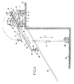
- the cabin 8 can thus be moved between a low position ( Figures 1 and 4) and a high position (figure 5), with the possibility of occupying positions intermediates ( Figures 6 and 7).
- the vertical displacement plane of the cabin 8 is located on the side of the displacement plane of the riser 6 and of the telescopic arm 7.
- the head 15 of the telescopic arm 7 is provided with a device for link 24, intended to receive various work equipment interchangeable, thus fixed at the front end of the arm 7.
- the equipment work can be in particular a bucket 25 ( Figures 2 and 6), a hook fixed or a lifting winch 26 (figure 3), a fork 27 (figures 4, 5 and 6) or a personnel lifting platform 28 (FIG. 7).
- the riser 6 In the folded transport position, as shown in Figure 1, the riser 6 is lowered substantially horizontally, and it rests on the support structure 19.
- the telescopic arm 7 is retracted, and folded over of the riser 6.
- the cabin 8 is lowered, and it is located at the front of the rotating chassis 4, on the side of the extension 6 and of the arm 7.
- the head 15 of the arm 7 and the bucket 25 take place in front of the base frame 1.
- Figure 4 illustrates, more specifically, the use of the carriage self-propelled with its riser 6 folded back, and resting on the support structure 19 present at the rear of the rotating chassis 4.
- the arm 7 can here pivot around the horizontal axis 16 kept fixed, between a substantially horizontal position and a substantially vertical position, this arm 7 which can, moreover, be telescoped.
- the self-propelled trolley is thus can be used as a single telescopic arm machine, for example for handling of a load 29 placed on a fork 27.
- the self-propelled trolley can also be used, as shown in the Figure 5, with its extension 6 deployed vertically, the telescopic arm 7 can have a variable inclination, and be more or less telescope.
- the machine can thus ensure the distribution of a load 29 above of a low building 30, or beyond an obstacle such as a wall.
- the cabin 8 is advantageously brought into high position, substantially at the upper end of the raises 6, the operator's line of vision 31 then passing over the building 30 or other obstacle, so as to keep the direct vision of the load 29 during the handling thereof.
- the self-propelled trolley is still usable with its extension 6 deployed horizontally towards the front, and extended by the telescopic arm 7, aligned horizontally with this extension 6. This position of use allows the distribution of a load 29 through an opening 32 of a building 30.
- Figure 6 illustrates other possibilities of use, allowing to carry out work below the support surface 33 of the carriage self-propelled.
- the extension 6 deployed forward, and with the telescopic arm 7 directed downwards (in dashed lines), it is possible to distribute a load 29 at the bottom of an excavation 34.
- the riser 6 held in an inclined position, and with the telescopic arm 7 folded over this extension 6 (drawn in solid lines), it is possible to move bucket 25 on an inclined plane 35, for earthworks: construction of an inclined structure (road embankment, bank of canal, dike), excavation.
- the equipment of work carried by the telescopic arm 7 it is also possible to carry out the handling rubble, pallets of materials, concrete, etc. along of the inclined plane 35.
- Figure 7 illustrates the possibilities of using the carriage self-propelled, equipped with a nacelle 28 kept horizontal, on which can take place one or more people.
- the nacelle 28 allows working at height, in the upper rear I and front II sectors (such previously defined), for example for the installation of frames or the cladding of buildings, even in narrow bays not allowing the complete rotation of the rotating chassis 4 around the vertical axis 5.
Landscapes
- Engineering & Computer Science (AREA)
- Transportation (AREA)
- Structural Engineering (AREA)
- Civil Engineering (AREA)
- Life Sciences & Earth Sciences (AREA)
- Geology (AREA)
- Mechanical Engineering (AREA)
- Forklifts And Lifting Vehicles (AREA)
- Jib Cranes (AREA)
- Body Structure For Vehicles (AREA)
Applications Claiming Priority (2)
| Application Number | Priority Date | Filing Date | Title |
|---|---|---|---|
| FR9907600A FR2794734B1 (fr) | 1999-06-10 | 1999-06-10 | Chariot automoteur a bras telescopique et rehausse |
| FR9907600 | 1999-06-10 |
Publications (2)
| Publication Number | Publication Date |
|---|---|
| EP1061034A1 true EP1061034A1 (de) | 2000-12-20 |
| EP1061034B1 EP1061034B1 (de) | 2003-12-17 |
Family
ID=9546852
Family Applications (1)
| Application Number | Title | Priority Date | Filing Date |
|---|---|---|---|
| EP20000420106 Expired - Lifetime EP1061034B1 (de) | 1999-06-10 | 2000-05-23 | Selbstangetriebener Wagen mit teleskopischem Arm und Hebungarm |
Country Status (6)
| Country | Link |
|---|---|
| EP (1) | EP1061034B1 (de) |
| JP (1) | JP2001019360A (de) |
| DE (1) | DE60007227T2 (de) |
| ES (1) | ES2211484T3 (de) |
| FR (1) | FR2794734B1 (de) |
| RU (1) | RU2260558C2 (de) |
Cited By (7)
| Publication number | Priority date | Publication date | Assignee | Title |
|---|---|---|---|---|
| CN100354195C (zh) * | 2003-05-13 | 2007-12-12 | 美国格若沃责任有限公司 | 折叠式顶部弯曲装置 |
| US8899905B2 (en) | 2007-12-27 | 2014-12-02 | Cargotec Patenter Ab | Boom truck for handling loads above and below ground level |
| CN108706333A (zh) * | 2018-08-06 | 2018-10-26 | 中国铁建重工集团有限公司 | 隧道钢拱架安装机械手和机械手工作平台 |
| CN109969958A (zh) * | 2019-03-06 | 2019-07-05 | 湖南双达机电有限责任公司 | 高空作业设备的伸缩臂架及高空作业设备 |
| CN110090379A (zh) * | 2019-06-05 | 2019-08-06 | 三一汽车制造有限公司 | 臂架组件和消防车 |
| CN115231344A (zh) * | 2022-09-03 | 2022-10-25 | 杭州中建云天科技有限公司 | 一种自动装车装置 |
| CN116271641A (zh) * | 2023-03-17 | 2023-06-23 | 沈阳捷通消防车有限公司 | 一种单折叠伸缩臂架结构及消防车 |
Families Citing this family (2)
| Publication number | Priority date | Publication date | Assignee | Title |
|---|---|---|---|---|
| US7048257B2 (en) * | 2003-09-19 | 2006-05-23 | Earth Tool Company, L.L.C. | Winch with telescoping mast |
| CN108455318B (zh) * | 2018-03-30 | 2019-09-06 | 长沙理工大学 | 一种多杆机构输送机 |
Citations (5)
| Publication number | Priority date | Publication date | Assignee | Title |
|---|---|---|---|---|
| US3957165A (en) * | 1973-12-20 | 1976-05-18 | Rubery Owen Mechanical Equipment | Straddle carriers |
| FR2444639A1 (fr) | 1978-12-20 | 1980-07-18 | Potain Sa | Equipement de manutention, notamment pour un engin automoteur |
| FR2457240A1 (fr) | 1979-05-22 | 1980-12-19 | Montgon Serge | Grue hydraulique associee a un vehicule porteur |
| FR2761972A1 (fr) | 1997-04-11 | 1998-10-16 | Modules Associes | Engin automoteur porte-outils perfectionne |
| EP0978472A2 (de) * | 1998-07-01 | 2000-02-09 | Grove U.S. LLC | Fahrbarer Kran |
Family Cites Families (2)
| Publication number | Priority date | Publication date | Assignee | Title |
|---|---|---|---|---|
| SU1650571A1 (ru) * | 1987-11-04 | 1991-05-23 | Pavlyuk Boris A | Подъемник дл обслуживани линий электропередач |
| FR2706882B1 (de) * | 1993-06-22 | 1995-08-11 | Potain Sa |
-
1999
- 1999-06-10 FR FR9907600A patent/FR2794734B1/fr not_active Expired - Fee Related
-
2000
- 2000-05-23 EP EP20000420106 patent/EP1061034B1/de not_active Expired - Lifetime
- 2000-05-23 DE DE2000607227 patent/DE60007227T2/de not_active Expired - Lifetime
- 2000-05-23 ES ES00420106T patent/ES2211484T3/es not_active Expired - Lifetime
- 2000-06-09 JP JP2000173752A patent/JP2001019360A/ja active Pending
- 2000-06-09 RU RU2000115169/11A patent/RU2260558C2/ru not_active IP Right Cessation
Patent Citations (5)
| Publication number | Priority date | Publication date | Assignee | Title |
|---|---|---|---|---|
| US3957165A (en) * | 1973-12-20 | 1976-05-18 | Rubery Owen Mechanical Equipment | Straddle carriers |
| FR2444639A1 (fr) | 1978-12-20 | 1980-07-18 | Potain Sa | Equipement de manutention, notamment pour un engin automoteur |
| FR2457240A1 (fr) | 1979-05-22 | 1980-12-19 | Montgon Serge | Grue hydraulique associee a un vehicule porteur |
| FR2761972A1 (fr) | 1997-04-11 | 1998-10-16 | Modules Associes | Engin automoteur porte-outils perfectionne |
| EP0978472A2 (de) * | 1998-07-01 | 2000-02-09 | Grove U.S. LLC | Fahrbarer Kran |
Cited By (8)
| Publication number | Priority date | Publication date | Assignee | Title |
|---|---|---|---|---|
| CN100354195C (zh) * | 2003-05-13 | 2007-12-12 | 美国格若沃责任有限公司 | 折叠式顶部弯曲装置 |
| US8899905B2 (en) | 2007-12-27 | 2014-12-02 | Cargotec Patenter Ab | Boom truck for handling loads above and below ground level |
| CN108706333A (zh) * | 2018-08-06 | 2018-10-26 | 中国铁建重工集团有限公司 | 隧道钢拱架安装机械手和机械手工作平台 |
| CN109969958A (zh) * | 2019-03-06 | 2019-07-05 | 湖南双达机电有限责任公司 | 高空作业设备的伸缩臂架及高空作业设备 |
| CN110090379A (zh) * | 2019-06-05 | 2019-08-06 | 三一汽车制造有限公司 | 臂架组件和消防车 |
| CN115231344A (zh) * | 2022-09-03 | 2022-10-25 | 杭州中建云天科技有限公司 | 一种自动装车装置 |
| CN115231344B (zh) * | 2022-09-03 | 2023-03-10 | 杭州中建云天科技有限公司 | 一种自动装车装置 |
| CN116271641A (zh) * | 2023-03-17 | 2023-06-23 | 沈阳捷通消防车有限公司 | 一种单折叠伸缩臂架结构及消防车 |
Also Published As
| Publication number | Publication date |
|---|---|
| RU2260558C2 (ru) | 2005-09-20 |
| DE60007227D1 (de) | 2004-01-29 |
| FR2794734B1 (fr) | 2001-07-13 |
| JP2001019360A (ja) | 2001-01-23 |
| ES2211484T3 (es) | 2004-07-16 |
| DE60007227T2 (de) | 2004-09-16 |
| FR2794734A1 (fr) | 2000-12-15 |
| EP1061034B1 (de) | 2003-12-17 |
Similar Documents
| Publication | Publication Date | Title |
|---|---|---|
| EP0536060B1 (de) | Selbsttätig klappbarer Kranausleger | |
| JPH06102518B2 (ja) | 釣合い重錘キヤリアを備えたクレーン | |
| FR2682156A1 (fr) | Engin mobile de forage. | |
| EP0362096B1 (de) | Fahrzeugtransporter mit einer teleskopierbaren Ladefläche | |
| FR2659311A1 (fr) | Dispositif motorise de prehension de charge a commande a distance. | |
| EP1048605B1 (de) | Multifunktionskran mit einem Teleskopausleger | |
| EP1061034B1 (de) | Selbstangetriebener Wagen mit teleskopischem Arm und Hebungarm | |
| EP1667931B1 (de) | Hebevorrichtung | |
| EP0786201B1 (de) | Ferngesteuerter Heckenschneidroboter mit selbsttätigen Niveaueinstellung | |
| EP1301431B9 (de) | Kran mit aus gliedern bestehendem kranarm | |
| FR2605619A1 (fr) | Engin repliable pour la manutention et le levage des charges | |
| EP0873964B1 (de) | Technik zum Aufrichten des Mastes für einen Teleskopkran | |
| FR2690883A1 (fr) | Mécanisme d'actionnement pour le bras arrière basculant de levage/tractage d'un véhicule de dépannage. | |
| EP1607363A2 (de) | Kran mit einem teleskopierbarem Ausleger | |
| FR2536735A1 (fr) | Chariot de travail notamment pour la pose des vitres de toitures des serres agricoles | |
| FR2509708A1 (fr) | Engin de levage transportable pour petits chantiers de construction | |
| EP1873114B1 (de) | Transportabler Turmkrahn mit einer mobilen Ballastvorrichtung | |
| EP1953112A1 (de) | Hubgerät | |
| FR2458503A1 (fr) | Appareil de manutention pour l'equipement, la finition et la renovation des immeubles | |
| FR2610614A1 (fr) | Appareil elevateur articule | |
| EP1057776B1 (de) | Kran mit aus Gliedern bestehendem Kranarm | |
| EP0077308B1 (de) | Fahrzeug zum Laden, Graben und Transportieren auf kurzen Strecken und zum Entladen von Materialien aus variablen Höhen | |
| EP2544984B1 (de) | Bewegliche hebeausrüstung | |
| FR2774670A1 (fr) | Engin roulant mobile a portee variable et fleche orientable telescopique | |
| EP1408162A1 (de) | Mastanordnung für eine Baumaschine |
Legal Events
| Date | Code | Title | Description |
|---|---|---|---|
| PUAI | Public reference made under article 153(3) epc to a published international application that has entered the european phase |
Free format text: ORIGINAL CODE: 0009012 |
|
| AK | Designated contracting states |
Kind code of ref document: A1 Designated state(s): BE DE ES IT |
|
| AX | Request for extension of the european patent |
Free format text: AL;LT;LV;MK;RO;SI |
|
| 17P | Request for examination filed |
Effective date: 20010129 |
|
| AKX | Designation fees paid |
Free format text: BE DE ES IT |
|
| GRAP | Despatch of communication of intention to grant a patent |
Free format text: ORIGINAL CODE: EPIDOSNIGR1 |
|
| GRAS | Grant fee paid |
Free format text: ORIGINAL CODE: EPIDOSNIGR3 |
|
| GRAA | (expected) grant |
Free format text: ORIGINAL CODE: 0009210 |
|
| AK | Designated contracting states |
Kind code of ref document: B1 Designated state(s): BE DE ES IT |
|
| REF | Corresponds to: |
Ref document number: 60007227 Country of ref document: DE Date of ref document: 20040129 Kind code of ref document: P |
|
| REG | Reference to a national code |
Ref country code: ES Ref legal event code: FG2A Ref document number: 2211484 Country of ref document: ES Kind code of ref document: T3 |
|
| PLBE | No opposition filed within time limit |
Free format text: ORIGINAL CODE: 0009261 |
|
| STAA | Information on the status of an ep patent application or granted ep patent |
Free format text: STATUS: NO OPPOSITION FILED WITHIN TIME LIMIT |
|
| 26N | No opposition filed |
Effective date: 20040920 |
|
| PGFP | Annual fee paid to national office [announced via postgrant information from national office to epo] |
Ref country code: BE Payment date: 20050609 Year of fee payment: 6 |
|
| PG25 | Lapsed in a contracting state [announced via postgrant information from national office to epo] |
Ref country code: BE Free format text: LAPSE BECAUSE OF NON-PAYMENT OF DUE FEES Effective date: 20060531 |
|
| BERE | Be: lapsed |
Owner name: *POTAIN Effective date: 20060531 |
|
| PGFP | Annual fee paid to national office [announced via postgrant information from national office to epo] |
Ref country code: DE Payment date: 20140428 Year of fee payment: 15 Ref country code: IT Payment date: 20140513 Year of fee payment: 15 Ref country code: ES Payment date: 20140520 Year of fee payment: 15 |
|
| REG | Reference to a national code |
Ref country code: DE Ref legal event code: R119 Ref document number: 60007227 Country of ref document: DE |
|
| PG25 | Lapsed in a contracting state [announced via postgrant information from national office to epo] |
Ref country code: IT Free format text: LAPSE BECAUSE OF NON-PAYMENT OF DUE FEES Effective date: 20150523 |
|
| PG25 | Lapsed in a contracting state [announced via postgrant information from national office to epo] |
Ref country code: DE Free format text: LAPSE BECAUSE OF NON-PAYMENT OF DUE FEES Effective date: 20151201 |
|
| REG | Reference to a national code |
Ref country code: ES Ref legal event code: FD2A Effective date: 20160628 |
|
| PG25 | Lapsed in a contracting state [announced via postgrant information from national office to epo] |
Ref country code: ES Free format text: LAPSE BECAUSE OF NON-PAYMENT OF DUE FEES Effective date: 20150524 |