EP1061606A2 - Dispositif et procédé pour connecter un câble plat avec des barres omnibus - Google Patents
Dispositif et procédé pour connecter un câble plat avec des barres omnibus Download PDFInfo
- Publication number
- EP1061606A2 EP1061606A2 EP00401682A EP00401682A EP1061606A2 EP 1061606 A2 EP1061606 A2 EP 1061606A2 EP 00401682 A EP00401682 A EP 00401682A EP 00401682 A EP00401682 A EP 00401682A EP 1061606 A2 EP1061606 A2 EP 1061606A2
- Authority
- EP
- European Patent Office
- Prior art keywords
- bus bars
- resin sheet
- insulator resin
- strip
- conductor strips
- Prior art date
- Legal status (The legal status is an assumption and is not a legal conclusion. Google has not performed a legal analysis and makes no representation as to the accuracy of the status listed.)
- Withdrawn
Links
Images


Classifications
-
- H—ELECTRICITY
- H01—ELECTRIC ELEMENTS
- H01R—ELECTRICALLY-CONDUCTIVE CONNECTIONS; STRUCTURAL ASSOCIATIONS OF A PLURALITY OF MUTUALLY-INSULATED ELECTRICAL CONNECTING ELEMENTS; COUPLING DEVICES; CURRENT COLLECTORS
- H01R4/00—Electrically-conductive connections between two or more conductive members in direct contact, i.e. touching one another; Means for effecting or maintaining such contact; Electrically-conductive connections having two or more spaced connecting locations for conductors and using contact members penetrating insulation
- H01R4/70—Insulation of connections
-
- H—ELECTRICITY
- H01—ELECTRIC ELEMENTS
- H01R—ELECTRICALLY-CONDUCTIVE CONNECTIONS; STRUCTURAL ASSOCIATIONS OF A PLURALITY OF MUTUALLY-INSULATED ELECTRICAL CONNECTING ELEMENTS; COUPLING DEVICES; CURRENT COLLECTORS
- H01R12/00—Structural associations of a plurality of mutually-insulated electrical connecting elements, specially adapted for printed circuits, e.g. printed circuit boards [PCB], flat or ribbon cables, or like generally planar structures, e.g. terminal strips, terminal blocks; Coupling devices specially adapted for printed circuits, flat or ribbon cables, or like generally planar structures; Terminals specially adapted for contact with, or insertion into, printed circuits, flat or ribbon cables, or like generally planar structures
- H01R12/50—Fixed connections
- H01R12/59—Fixed connections for flexible printed circuits, flat or ribbon cables or like structures
- H01R12/63—Fixed connections for flexible printed circuits, flat or ribbon cables or like structures connecting to another shape cable
-
- H—ELECTRICITY
- H01—ELECTRIC ELEMENTS
- H01R—ELECTRICALLY-CONDUCTIVE CONNECTIONS; STRUCTURAL ASSOCIATIONS OF A PLURALITY OF MUTUALLY-INSULATED ELECTRICAL CONNECTING ELEMENTS; COUPLING DEVICES; CURRENT COLLECTORS
- H01R12/00—Structural associations of a plurality of mutually-insulated electrical connecting elements, specially adapted for printed circuits, e.g. printed circuit boards [PCB], flat or ribbon cables, or like generally planar structures, e.g. terminal strips, terminal blocks; Coupling devices specially adapted for printed circuits, flat or ribbon cables, or like generally planar structures; Terminals specially adapted for contact with, or insertion into, printed circuits, flat or ribbon cables, or like generally planar structures
- H01R12/50—Fixed connections
- H01R12/59—Fixed connections for flexible printed circuits, flat or ribbon cables or like structures
- H01R12/65—Fixed connections for flexible printed circuits, flat or ribbon cables or like structures characterised by the terminal
- H01R12/67—Fixed connections for flexible printed circuits, flat or ribbon cables or like structures characterised by the terminal insulation penetrating terminals
-
- H—ELECTRICITY
- H01—ELECTRIC ELEMENTS
- H01R—ELECTRICALLY-CONDUCTIVE CONNECTIONS; STRUCTURAL ASSOCIATIONS OF A PLURALITY OF MUTUALLY-INSULATED ELECTRICAL CONNECTING ELEMENTS; COUPLING DEVICES; CURRENT COLLECTORS
- H01R35/00—Flexible or turnable line connectors, i.e. the rotation angle being limited
- H01R35/02—Flexible line connectors without frictional contact members
Definitions
- the present invention relates to a structure and method for connecting a flat electrical cable to bus bars. More particularly, the invention concerns a connection between relaying bus bars, and a flat cable used for steering equipment in automobiles.
- a flat cable is contained in a cable reel. The flat cable is then connected to lead cables joined to external circuits, through the relaying bus bars.
- Figs. 1 and 2 show a ring-shaped cable enclosure comprising a fixed element 1 joined to a steering shaft.
- the cable enclosure further comprises a mobile element 2 connected to a steering wheel in a freely rotatable way around the fixed element 1.
- a flat cable 3 is then stored in the cable enclosure in a helically wound state.
- the flat cable 3 has a given length and each of its two ends is connected to an edge of a relay bus bar 5 attached to inner cases 4. The latter are respectively joined to the fixed element 1 and the mobile element 2.
- the other edge of the relay bus bar 5 is connected to lead cables 6 leading to external circuits.
- the flat cable is wound or unwound in unison with the rotation of the mobile element 2.
- a plurality of relay bus bars 5 having a narrow width are fitted into grooves aligned in the inner case 4, and insert-molded with the latter.
- An end portion of the flat cable 3 is stripped of its resin coating, so that aligned conductor strips 3a are exposed.
- These conductor strips 3a are superposed on the plurality of relay bus bars 5, and are bonded by ultrasonic welding.
- a lid 7 is then put on the inner case 4, such that the joint section is protected.
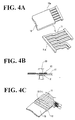
- the widths of the conductor strips 3a of flat cable 3 are reduced, as are the setting-up pitches of the conductor strips 3a. Consequently, the connection between the conductor strips 3a and the relay bus bars 5 are mechanically weakened, to the extent that the joint section can no longer be protected solely by the inner case 5 and the lid 7. Further, the ribs formed by the neighboring grooves of inner case 4, which isolate the conductor strip layers from each other, are also rendered smaller and narrower, so that the circuits can no longer be insulated sufficiently from one another.
- the relay bus bars 5 are insert-molded into the inner case 4, the relay bus bars 5 are made smaller. Their mechanical strength is then reduced. Accordingly, the relay bus bars 5 are easily broken during insert-molding. Moreover, their fixing positions in the inner case 4 become more prone to variations.
- manufacture of dies for insert-molding relay bus bars 5 with an inner case 4, and for a protective lid 7, incurs high costs.
- a primary object of the present invention is to provide a joint section between a flat cable and bus bars which is securely protected and insulated, and to reduce production costs.
- a structure for connecting a flat cable to bus bars, the flat cable exposing conductor strips includes bus bars and conductor strips adhered onto the bus bars, thereby forming a joint section including strip layers and strip gaps.
- the structure further includes a first and a second insulator resin sheet placed respectively on a first and a second face of the joint section.
- at least the first insulator resin sheet is configured such that it penetrates into the strip gaps and adheres onto the second insulator resin sheet, so as to form insulating grooves.
- At least the first insulator resin sheet is a thermoplastic insulator resin sheet.
- the conductor strips may be adhered onto the bus bars by welding.
- the strip layers include at least one of the configurations chosen from the group consisting of punched holes, embossed figures and rivet cramping.
- the structure may further comprise a holder and a lid made of an insulator resin and enclosing, the joint section including the first and the second insulator resin sheet.
- the above methods may further comprise the step of enclosing the joint section covered with the thermoplastic insulator resin sheet and/or the insulator resin sheet, with a holder and a lid.
- the insulator resin sheet is made of polyethylene terephthalate, and has a thickness of about 70 ⁇ m.
- a joint section (including welded strip layers), that includes bus bars and conductor strips aligned in parallel, is arranged on an insulator resin sheet (base plate). Another insulator resin sheet is then placed on the joint section and spread thereon.
- the welded bus bars and conductor strips are covered with an insulator resin sheet from both sides thereof, the welded strip layers are mechanically reinforced by the insulator resin sheet, and protection of these strips is greatly improved.
- both lateral faces of each of the welded strip layers are likewise covered with the insulator resin sheet.
- the insulator resin sheet (conductor strip side) is also adhered to the portions of base plate placed between the welded strip layers, thereby forming an insulating section. This insulating section improves the isolation between the circuits. Accordingly, it is no longer needed to insert-mold the bus bars in an inner case, or to manufacture a molded cover, as done in the past. Production costs can thus be greatly reduced.
- one face of the insulator resin sheet which is put into contact with the joint section is preferably painted with an adhesive.
- the bus bars are not loaded on the base plate on the outset. Instead, the conductor strips of a flat cable are first superposed on the bus bars. Thereafter, they are bonded as such by ultrasonic welding or a similar means, and then placed on the base plate (one of the insulator resin sheets).
- both ends of the aligned bus bars may be joined beforehand by a respective carrier band. In this state, the conductor strips are superposed on the bus bars and welded. After welding, the carriers are cut off, to free the circuits.
- the bus bars are first placed on the base plate.
- the conductor strips of a flat cable are then superposed on the bus bars.
- the bus bars and the conductor strips are bonded by ultrasonic welding or a similar means.
- the base plate may be provided with small holes arranged at a given interval. The bus bars and the conductor elements are then arranged on the small holes, and welding is performed.
- the conductor strips, welded on the bus bars, are covered with a thermoplastic insulator resin sheet after the welding.
- the joint section is covered with an insulator resin sheet from both faces thereof.
- the sheets are then adhered by heated devices, so that not only the conductor strips and the bus bars are firmly bonded, but also the joint section itself is better protected from outside.
- the insulator resin sheets may be sized up appropriately, depending on the number of the bus bars and conductor strips used. An increase in the number of circuits can thus be easily met.
- the devices respectively comprise a pressing plane with alternating concave and convex configurations.
- the convex configurations press the insulator resin sheets into the strip gaps formed between the strip layers. The sheets thus inserted between the strip gaps prevent interactions between the conductor strips.
- a second fixing step may be performed by piecing, embossing or rivet cramping the insulator resin sheets.
- Such a second fixing strengthens further the adhesion between the conductor elements and the bus bars which had already been adhered firmly by the insulator resin sheets. For example, when the conductor strips and the bus bars are punched from above the resin sheets, there occur returns inside the pierced holes. These returns hold the bus bars and the conductor strips together and solidify the adhesion. Likewise, when the resin sheets are embossed, the conductor strips and the bus bars are undulated, so that they are held together more firmly.
- the conductor elements and the bus bars may be pierced, and clamped by rivets through the pierced holes. Besides the above mentioned fixing methods, laser welding can also be applied.
- the whole surface of the joint section X including the strip layers and the strip gaps is then laminated with an insulator resin sheet 16 made of polyethylene terephthalate having a thickness of 70 ⁇ m. Consequently, the strip layers (including the conductor elements 13 and the bus bars 11) are covered from above with the insulator resin sheet 16. Likewise, the strip gaps 15 are also covered with the insulator resin sheet 16, such that the this sheet 16 is laminated on the base plate 12 along the strip gaps.
- the base plate 12 is locked to a fixed and a mobile element of a cable reel.
- the other end of the bus bars 11 is connected to lead cables 17 linking to external circuits.
- the joint section is prepared according to the method illustrated in Figs. 4A to 4E.
- a plurality of bus bars 11 include two end portions, each of which is joined by welding through a respective carrier band 11a.
- the conductor strips 13 in the flat cable 10 are then exposed by stripping off an insulator film 10a. These conductor strips 13 are superposed on one end portion of the bus bars 11.
- the superposed bus bars 11 and conductor strips 13 are bonded by an ultrasonic welding machine 20, so as to form strip layers between the bus bars 11 and the corresponding conductor strips 13.
- the carrier bands 11a are cut off the bus bars 11 so as to free the latter.
- thermoplastic insulator resin sheet 16 has a size adapted to cover the whole surface of the joint section X. This sheet 16 is then placed on the joint section X including the strip layers and the strip gaps. One face of the sheet 16 may be painted with an adhesive, so as to adhere to the joint section X more firmly.
- a device 21 comprising a pressing plane with alternating (or sequential) concave and convex configurations 21a and 21b.
- the device 21 is made of a metal having necessary hardness and heat conductivity. Alternating intervals between the concave configurations 21a and the convex configurations 21b correspond to the pitches between the strip layers formed by the conductor elements 13 and the bus bars 11.
- the device 21 is heated and pressed onto the thermoplastic insulator resin sheet 16.
- the strip layers including the bus bars 11 and the conductor strips 13 are laminated with the insulator resin sheet 16 by virtue of the concave configurations 21a, while the base plate 12 is directly covered with the sheet 16 in the strip gaps 15, by virtue of the convex configurations.
- the above operation thus gives the structure shown in Figs. 3A and 3B.
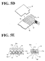
- Figs. 5A to 5E show a second connecting method.
- bus bars 11 are placed on a base plate 12', before the conductor strips 13 in a flat cable 10 are welded to the bus bars 11 (Fig. 5A).
- the bus bars 11 may be provided with pin holes, into which engage pins projecting from the base plate 12'.
- the base plate 12' comprises holes 12a' in positions located under the bus bars 11 of the strip layers. These holes 12a' allows to conduct ultrasonic welding.
- an insulator resin sheet 16 is placed on the joint section X as in the case of the first method.
- the insulator resin sheet 16 is then pressed by device 21, to produce a structure shown in Figs. 3A and 3B.
- Figs. 6A and 6B show a second aspect of the connecting structures of the invention.
- exposed conductor elements 13 are superposed on aligned bus bars 11, forming the joint section.
- the insulator resin sheets 16 and 17 are then adhered on the joint section from each side thereof. Thereafter, holes 14b are formed by piercing all the layers.
- the structure for connecting the conductor strips to the bus bars are manufactured according to the method illustrated in Figs. 7A, 7B and 7C.
- the conductor strips 13 and the bus bars 11 are arranged as in the case of the first aspect of the invention.
- the portions of the bus bars other than those connected to the conductor elements 13 may be formed by insert-molding as before.
- the joint section X of the conductor elements 13 and the bus bars 11 are flanked by two insulator resin sheets 16 and 17. These sheets 16 and 17 are preferably thermoplastic sheets. In the present embodiment, a 70 ⁇ m-thick polyethylene terephthalate is used. The latter is cut out to a size covering the whole surface of the joint section X.
- the insulator resin sheets 16 and 17 thus arranged are adhered onto the joint section X by a first device 26 and a second device 27.
- These devices 26 and 27 are of the same nature as that used in the first aspect of the invention.
- One face of the first device 26 forms a pressing plane having alternating concave and convex configurations 26a and 26b.
- the second device 27 likewise comprises alternating concave configurations 27a and convex configurations 27b.
- the first and second devices 26 and 27 are then heated, and pressed onto the first and second insulator resin sheets 16 and 17 from opposite sides towards the surfaces of the joint section 14 (first fixing step).
- the concave configurations 26a and 27a thus adhere the conductor strips 13 to the bus bars 11, as shown in Fig. 7C.
- the insulator resin sheets become soft, adapt to the outer figure of the joint section X, and adhere to the lateral faces of the strip layers 14.
- the convex configurations 26b and 27b penetrate into the strip gaps 14a, where the first and the second insulator resin sheets 16 and 17 adhere to each other.
- the contact faces of the opposing insulator resin sheets 16 and 17 may be painted with an adhesive.
- the strip gaps 14a surrounding the strip layers 14 of conductor elements 13 and bus bars 11 are covered with the laminates of insulator resin sheets 16 and 17. Accordingly, even if the conductor strips are narrow and lack mechanical resistance, the joint section is reinforced by these resin sheets 16 and 17. Further, as the insulator resin sheets 16 and 17 fill the strip gaps 14a, short circuits can be prevented efficiently.
- the strip layers 14 after the first fixing step may be punched from above the insulator resin sheets 16 and 17 by a press having a piercing die 30 (second fixing step).
- the strip layers 14 are first protected by the laminated insulator resin sheets. Then, through the second fixing step, the pierced surface of the holes 14b is coated with the same resin sheet 16 or 17, from the rim portions of the holes towards the inside.
- the second fixing step may be omitted.
- the contact surface between the conductor strips 13 and the bus bars 11 may be increased so as to enhance adhesion.
- the conductor strips 13 exposed from the flat cable may be lengthened, so as to be bent before being superposed on the bus bars 11;
- the lengthened conductor elements 13 may be folded around the edge of the bus bars 11.
- the insulator resin sheets 16 and 17 are covered after the conductor strips 13 having been folded.
- the bus bars 11 may be pierced prior to the second fixing step.
- the conductor strips 13 and the insulator resin sheets 16 and 17 are then pierced in the second fixing step, so that the strip layers 14 can be punched more easily, and returns 13a of the conductor strips 13 bore into the bus bars 11 more smoothly.
- their contact surfaces may be bonded by laser welding through the holes 14b.
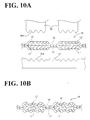
- Figs. 10A and 10B show a structure of strip layers 14 according to a second example, in which conductor elements 13' exposed from a flat cable 10' are bound to bus bars 11'.
- the first fixing step of the strip layers 14' is effected as in the case of the first example.
- the second fixing step involves embossing instead of punching.
- the above embossing process employs dies 30' and 31' having undulating pressing plane 30a' and 31a'. These dies are pressed against the strip layers 14' from both sides thereof. After the strip layers 14' are embossed, the conductor strips 13' and the bus bars 11' are undulated by plastic transformation, and firmly adhered to each other.
- Figs. 11A and 11B show a structure of strip layers 14" according to a third example, in which conductor elements 13" exposed from a flat cable 10" are bound to bus bars 11".
- the strip layers 14" are formed at the second fixing step, to yield holes 14b", as in the case of the first example. Rivets 35" are then inserted into the holes 14b". Edge portions 35a" of the rivets 35" are cramped to form cramping heads 35c", so that the conductor strips 13" and the bus bars 11" are fixed even more firmly.
- the rivets 35" are made of low conductivity materials such as aluminum or brass. Accordingly, although rivet heads 35b" emerge from the insulator resin sheets 16" and 17", short circuits through these rivet heads may be prevented.
- Figs. 12A and 12B show a third aspect of the connecting structures of the invention.
- the joint section is inserted into a holder 18 made into the form of a box.
- the holder 18 is joined to a lid 19 through a hinge.
- the holder 18 and the lid 19 are integrally formed of a resin.
- the holder 18 is locked to a fixed element and a mobile element of cable reel. Further, the other end of the bus bars 11 is connected to lead cables 20 leading to external circuits.
- a plurality of bus bars 11 have two end portions which are joined by carrier bands 11 la by welding.
- the conductor strips 13 of flat cable 10 are then exposed by stripping off an insulator film 10a. These conductor strips 13 are superposed on one end portion of the bus bars 11.
- the superposed bus bars 11 and conductor strips 13 are bonded by an ultrasonic welding machine 20, so as to form strip layers 14 including the bus bars 11 and the corresponding conductor elements 13.
- the carrier band 11a is cut off the bus bars 11 so as to free the latter.
- the strip layers 14 are flanked by the respective thermoplastic insulator resin sheets 16 and 17 from both sides of the strip layers 14.
- the faces of the resin sheets that contact with the strip layers 14 are preliminarily painted with an adhesive.
- a first device 26 and a second device 27 as in the foregoing embodiments.
- the devices 26 and 27 are heated and pushed onto the respective thermoplastic insulator resin sheets 16 and 17.
- the strip layers including the bus bars 11 and conductor elements 13 are coated with the insulator resin sheets 16 and 17 by virtue of the concave configurations 26a and 27a, while the sheets 16 and 17 are adhered to each other in the strip gaps 14a by the convex configurations 26b and 27b, so as to form an insulating strips 15.
- the joint section including the laminated bus bars 11 and conductor strips 13, is inserted into the holder 18 and covered with a lid 19.
- the holder 18 and the lid 19 are then closed by locking.
- the resistance of the joint section may not be sufficient. Even in such a case, the two-side laminates of the resin sheets 16 and 17, and the holder 18 and lid 19 combination secure the protection of the joint section.
- the two faces of the joint section including bus bars and conductor elements are completely laminated with the insulator resin sheet, so that protection of the strip layers are secured, and the insulation is improved.
- the joint section is contained in the holder and lid combination, so that protection of the joint section is even more complete.
- the invention may employ an insulator resin sheet as a base plate, instead of an inner case in which bus bars are to be insert-molded.
- the hitherto-used inner case included a lid having a complex configuration.
- Such a complicated construction can now be replaced by a base plate which is prepared very easily. Production costs are thus reduced drastically.
- there is no longer a need to use a lid and the joint section including bus bars and conductor strips can be miniaturized. As such a structure requires less space, it gives an important advantage when stored in a cable reel.
- the strip layers become less resistant. Even in such a case, the strip layers can be strengthened by the laminates of insulator resin sheet, and their insulation is nevertheless enhanced.
- the resin sheets are adhered to each other in a hot and flexible state by concave-and-convex configured devices.
- the insulator resin then penetrates into strip gaps formed between neighboring strip layers, thereby securing insulation between the strip layers.
- the insulator resin sheets may be cut off as desired, as a function of the number of circuits contained in the joint section. An increase or change of the circuit number can thus be responded to very easily. Moreover, to achieve the adhesion between the conductor strips and the bus bars, it is no longer needed to employ costly apparatus, such as a resistance welding machine or an ultrasonic welding machine. Installation costs are thus reduced.
- the bus bars sometimes include whiskers or barbs. Even in such a case, the insulator resin sheet laminated thereon can prevent spurious contacts between the neighboring bus bars. Further, the opposing lateral faces of the strip layers, as well as the base plate in the strip gaps, are covered with the insulator resin sheet. Accordingly, even when the strips layers are aligned at a close pitch, there occurs no short circuit between the neighboring strip layers. A good insulation can thus be secured.
Landscapes
- Multi-Conductor Connections (AREA)
- Coupling Device And Connection With Printed Circuit (AREA)
Applications Claiming Priority (6)
| Application Number | Priority Date | Filing Date | Title |
|---|---|---|---|
| JP17019699 | 1999-06-16 | ||
| JP11170196A JP2001006772A (ja) | 1999-06-16 | 1999-06-16 | フラットケーブルとバスバーとの接続構造及び接続方法 |
| JP17087499 | 1999-06-17 | ||
| JP17087499A JP2001006773A (ja) | 1999-06-17 | 1999-06-17 | フラットケーブルとバスバーとの接続構造及び接続方法 |
| JP17249699 | 1999-06-18 | ||
| JP11172496A JP2001006774A (ja) | 1999-06-18 | 1999-06-18 | フラットケーブルとバスバーとの接続方法及び該方法で形成された接続構造 |
Publications (2)
| Publication Number | Publication Date |
|---|---|
| EP1061606A2 true EP1061606A2 (fr) | 2000-12-20 |
| EP1061606A3 EP1061606A3 (fr) | 2004-05-19 |
Family
ID=27323315
Family Applications (1)
| Application Number | Title | Priority Date | Filing Date |
|---|---|---|---|
| EP00401682A Withdrawn EP1061606A3 (fr) | 1999-06-16 | 2000-06-14 | Dispositif et procédé pour connecter un câble plat avec des barres omnibus |
Country Status (2)
| Country | Link |
|---|---|
| US (1) | US6444910B1 (fr) |
| EP (1) | EP1061606A3 (fr) |
Cited By (4)
| Publication number | Priority date | Publication date | Assignee | Title |
|---|---|---|---|---|
| WO2020094690A1 (fr) | 2018-11-07 | 2020-05-14 | Iee International Electronics & Engineering S.A. | Encapsulation multicouche souple de connexions électriques |
| LU101059B1 (en) * | 2018-12-17 | 2020-06-17 | Iee Sa | Flexible Multilayer Encapsulation of Electrical Connections |
| CN113168938A (zh) * | 2018-12-13 | 2021-07-23 | 株式会社自动网络技术研究所 | 布线部件 |
| US11908597B2 (en) * | 2021-10-13 | 2024-02-20 | Yazaki Corporation | Flat electric wire and method for manufacturing flat electric wire |
Families Citing this family (17)
| Publication number | Priority date | Publication date | Assignee | Title |
|---|---|---|---|---|
| JP2002374075A (ja) * | 2001-06-13 | 2002-12-26 | Fujitsu Ten Ltd | 配線接続方法及び配線接続構造 |
| US7339114B2 (en) * | 2002-04-04 | 2008-03-04 | Fujikura Ltd. | Cable, cable connection method and cable welder |
| AU2003204534A1 (en) * | 2002-06-28 | 2004-01-22 | James E Cotter | Apparatus for detecting metal objects being put into a trash can |
| DE10250930B3 (de) * | 2002-10-31 | 2004-08-05 | Fci | Verfahren zur elektrischen Verbindung eines Leiters mit einem Kontaktelement |
| JP4321400B2 (ja) * | 2004-08-05 | 2009-08-26 | 住友電装株式会社 | バスバー |
| JP4644559B2 (ja) * | 2005-08-08 | 2011-03-02 | 矢崎総業株式会社 | 電磁溶接方法 |
| JPWO2007023517A1 (ja) * | 2005-08-22 | 2009-02-26 | 日立プラズマディスプレイ株式会社 | フラットケーブルおよびプラズマディスプレイ装置 |
| JP2010110197A (ja) * | 2008-09-30 | 2010-05-13 | Yamaha Motor Co Ltd | 電線の止水構造および船舶用推進機 |
| DE102008050000A1 (de) * | 2008-09-30 | 2010-04-01 | Fraunhofer-Gesellschaft zur Förderung der angewandten Forschung e.V. | Verfahren zum gleichzeitigen mechanischen und elektrischen Verbinden von zwei Teilen |
| JP5748189B2 (ja) * | 2009-11-30 | 2015-07-15 | 矢崎総業株式会社 | 配索材の接続構造 |
| CN203631172U (zh) * | 2011-04-07 | 2014-06-04 | 3M创新有限公司 | 高速传输电缆 |
| DE102012015215B3 (de) * | 2012-08-03 | 2014-02-20 | Carl Freudenberg Kg | Anordnung mit Stromsammelschienen |
| JP6082547B2 (ja) * | 2012-09-04 | 2017-02-15 | 株式会社アテックス | バスバーインサート樹脂成形品の製造方法 |
| DE102013002740A1 (de) * | 2013-02-19 | 2014-08-21 | Wieland Electric Gmbh | Flachkabel mit gerillter und planter Oberfläche |
| JP6056639B2 (ja) * | 2013-05-07 | 2017-01-11 | 株式会社オートネットワーク技術研究所 | 端子、端子付き電線および端子付き電線の製造方法 |
| CN105702358B (zh) * | 2016-03-29 | 2018-07-27 | 江苏金坤科技有限公司 | 降低接触电阻且粘接牢固的补强板 |
| JP6988399B2 (ja) * | 2016-12-05 | 2022-01-05 | トヨタ自動車株式会社 | 車載用バッテリリレー接続構造 |
Family Cites Families (8)
| Publication number | Priority date | Publication date | Assignee | Title |
|---|---|---|---|---|
| JPH0359971A (ja) | 1989-07-28 | 1991-03-14 | Yazaki Corp | フラット回路体の接続構造 |
| JPH0492377A (ja) * | 1990-08-06 | 1992-03-25 | Yazaki Corp | 電線の接続部 |
| JP3349581B2 (ja) | 1994-03-07 | 2002-11-25 | 矢崎総業株式会社 | フラットケーブル用ジョイントボックス |
| JP2914879B2 (ja) * | 1994-12-27 | 1999-07-05 | 矢崎総業株式会社 | フラットケーブルの接続構造 |
| JP3059971B2 (ja) | 1995-04-17 | 2000-07-04 | 株式会社高岳製作所 | 絶縁ブッシングの支持装置 |
| JP3110998B2 (ja) * | 1995-07-31 | 2000-11-20 | 矢崎総業株式会社 | フラット回路体のジョイント部及びその製造方法 |
| JPH09199196A (ja) * | 1996-01-23 | 1997-07-31 | Alps Electric Co Ltd | フラットケーブルと端子の接続構造 |
| JP3253541B2 (ja) | 1996-10-25 | 2002-02-04 | アルプス電気株式会社 | フラットケーブルと端子の接続構造 |
-
2000
- 2000-06-14 US US09/593,419 patent/US6444910B1/en not_active Expired - Fee Related
- 2000-06-14 EP EP00401682A patent/EP1061606A3/fr not_active Withdrawn
Cited By (8)
| Publication number | Priority date | Publication date | Assignee | Title |
|---|---|---|---|---|
| WO2020094690A1 (fr) | 2018-11-07 | 2020-05-14 | Iee International Electronics & Engineering S.A. | Encapsulation multicouche souple de connexions électriques |
| CN112970153A (zh) * | 2018-11-07 | 2021-06-15 | Iee国际电子工程股份公司 | 电连接柔性多层封装 |
| DE112019005566T5 (de) | 2018-11-07 | 2021-07-29 | Iee International Electronics & Engineering S.A. | Flexible Mehrschichtkapselung von elektrischen Verbindungen |
| CN112970153B (zh) * | 2018-11-07 | 2023-08-08 | Iee国际电子工程股份公司 | 电连接柔性多层封装 |
| CN113168938A (zh) * | 2018-12-13 | 2021-07-23 | 株式会社自动网络技术研究所 | 布线部件 |
| CN113168938B (zh) * | 2018-12-13 | 2023-08-15 | 株式会社自动网络技术研究所 | 布线部件 |
| LU101059B1 (en) * | 2018-12-17 | 2020-06-17 | Iee Sa | Flexible Multilayer Encapsulation of Electrical Connections |
| US11908597B2 (en) * | 2021-10-13 | 2024-02-20 | Yazaki Corporation | Flat electric wire and method for manufacturing flat electric wire |
Also Published As
| Publication number | Publication date |
|---|---|
| US6444910B1 (en) | 2002-09-03 |
| EP1061606A3 (fr) | 2004-05-19 |
Similar Documents
| Publication | Publication Date | Title |
|---|---|---|
| US6444910B1 (en) | Structure and method for connecting a flat cable to bus bars | |
| US6247977B1 (en) | Connector for flat cable | |
| EP1157892B1 (fr) | Joint de faisceau de câbles | |
| EP1172826A2 (fr) | Câble plat et sa méthode de fabrication | |
| JP2009093934A (ja) | シールド電線及びシールド電線の製造方法 | |
| JP3011041B2 (ja) | 平型多心電線 | |
| JP2003219530A (ja) | シールド電線とアース線の接続方法、接続構造および接続用超音波溶着装置 | |
| JP2001307559A (ja) | 配線材および該配線材の接続構造 | |
| JP4258674B2 (ja) | 同軸フラットケーブルおよびその製造方法 | |
| JP4907763B2 (ja) | 平型シールドハーネス及び平型シールドハーネスの製造方法 | |
| JP2021168278A (ja) | 配線部材 | |
| JP5114152B2 (ja) | フレキシブルフラットケーブル及びその製造方法 | |
| JP4855572B2 (ja) | 平型シールドハーネス及び平型シールドハーネスの製造方法 | |
| JP2005135823A (ja) | フラットハーネスの分岐構造及びその製造方法 | |
| JP5110003B2 (ja) | 同軸フラットケーブルの製造方法 | |
| JP4704588B2 (ja) | 導体薄膜シート及びシールドハーネス | |
| US20250054656A1 (en) | Electric wire with terminal and method of manufacturing the same | |
| JP2001006774A (ja) | フラットケーブルとバスバーとの接続方法及び該方法で形成された接続構造 | |
| JPH07111114A (ja) | シールド付テープ電線の製造方法 | |
| JP3061220B2 (ja) | フラットワイヤハーネスの製造方法 | |
| JP2001006773A (ja) | フラットケーブルとバスバーとの接続構造及び接続方法 | |
| KR102382788B1 (ko) | 플렉시블 부스바 제조방법 및 이에 의해 제조된 플렉시블 부스바 | |
| JP4028143B2 (ja) | 絶縁処理された端末部を有するフラットケーブルの製造方法 | |
| JP2005093267A (ja) | フラットハーネスの分岐構造及びその製造方法 | |
| EP0945918A2 (fr) | Connecteur électrique |
Legal Events
| Date | Code | Title | Description |
|---|---|---|---|
| PUAI | Public reference made under article 153(3) epc to a published international application that has entered the european phase |
Free format text: ORIGINAL CODE: 0009012 |
|
| 17P | Request for examination filed |
Effective date: 20000617 |
|
| AK | Designated contracting states |
Kind code of ref document: A2 Designated state(s): AT BE CH CY DE DK ES FI FR GB GR IE IT LI LU MC NL PT SE |
|
| AX | Request for extension of the european patent |
Free format text: AL;LT;LV;MK;RO;SI |
|
| PUAL | Search report despatched |
Free format text: ORIGINAL CODE: 0009013 |
|
| AK | Designated contracting states |
Kind code of ref document: A3 Designated state(s): AT BE CH CY DE DK ES FI FR GB GR IE IT LI LU MC NL PT SE |
|
| AX | Request for extension of the european patent |
Extension state: AL LT LV MK RO SI |
|
| RIC1 | Information provided on ipc code assigned before grant |
Ipc: 7H 01R 4/70 B Ipc: 7H 01R 12/08 A |
|
| STAA | Information on the status of an ep patent application or granted ep patent |
Free format text: STATUS: THE APPLICATION HAS BEEN WITHDRAWN |
|
| 18W | Application withdrawn |
Effective date: 20040713 |