EP1063406B1 - Système de tuyauterie avec un papillon - Google Patents
Système de tuyauterie avec un papillon Download PDFInfo
- Publication number
- EP1063406B1 EP1063406B1 EP00111985A EP00111985A EP1063406B1 EP 1063406 B1 EP1063406 B1 EP 1063406B1 EP 00111985 A EP00111985 A EP 00111985A EP 00111985 A EP00111985 A EP 00111985A EP 1063406 B1 EP1063406 B1 EP 1063406B1
- Authority
- EP
- European Patent Office
- Prior art keywords
- section
- cross
- throttle valve
- internal combustion
- combustion engine
- Prior art date
- Legal status (The legal status is an assumption and is not a legal conclusion. Google has not performed a legal analysis and makes no representation as to the accuracy of the status listed.)
- Expired - Lifetime
Links
- 238000002485 combustion reaction Methods 0.000 claims abstract description 33
- 239000012530 fluid Substances 0.000 claims abstract description 10
- 238000000034 method Methods 0.000 claims abstract description 8
- 238000011161 development Methods 0.000 claims description 2
- 230000001133 acceleration Effects 0.000 description 4
- 230000000694 effects Effects 0.000 description 3
- 230000002349 favourable effect Effects 0.000 description 3
- 239000000243 solution Substances 0.000 description 3
- 238000004519 manufacturing process Methods 0.000 description 2
- 230000006978 adaptation Effects 0.000 description 1
- 230000036461 convulsion Effects 0.000 description 1
- 230000002950 deficient Effects 0.000 description 1
- 238000012217 deletion Methods 0.000 description 1
- 230000037430 deletion Effects 0.000 description 1
- 238000001514 detection method Methods 0.000 description 1
- 230000018109 developmental process Effects 0.000 description 1
- 238000010586 diagram Methods 0.000 description 1
- 239000007789 gas Substances 0.000 description 1
- 238000002347 injection Methods 0.000 description 1
- 239000007924 injection Substances 0.000 description 1
- 238000009434 installation Methods 0.000 description 1
- 239000000463 material Substances 0.000 description 1
- 238000005192 partition Methods 0.000 description 1
- 230000001681 protective effect Effects 0.000 description 1
Images
Classifications
-
- F—MECHANICAL ENGINEERING; LIGHTING; HEATING; WEAPONS; BLASTING
- F02—COMBUSTION ENGINES; HOT-GAS OR COMBUSTION-PRODUCT ENGINE PLANTS
- F02M—SUPPLYING COMBUSTION ENGINES IN GENERAL WITH COMBUSTIBLE MIXTURES OR CONSTITUENTS THEREOF
- F02M35/00—Combustion-air cleaners, air intakes, intake silencers, or induction systems specially adapted for, or arranged on, internal-combustion engines
- F02M35/10—Air intakes; Induction systems
- F02M35/10006—Air intakes; Induction systems characterised by the position of elements of the air intake system in direction of the air intake flow, i.e. between ambient air inlet and supply to the combustion chamber
- F02M35/10013—Means upstream of the air filter; Connection to the ambient air
-
- F—MECHANICAL ENGINEERING; LIGHTING; HEATING; WEAPONS; BLASTING
- F02—COMBUSTION ENGINES; HOT-GAS OR COMBUSTION-PRODUCT ENGINE PLANTS
- F02D—CONTROLLING COMBUSTION ENGINES
- F02D9/00—Controlling engines by throttling air or fuel-and-air induction conduits or exhaust conduits
- F02D9/08—Throttle valves specially adapted therefor; Arrangements of such valves in conduits
- F02D9/10—Throttle valves specially adapted therefor; Arrangements of such valves in conduits having pivotally-mounted flaps
- F02D9/1035—Details of the valve housing
- F02D9/104—Shaping of the flow path in the vicinity of the flap, e.g. having inserts in the housing
-
- F—MECHANICAL ENGINEERING; LIGHTING; HEATING; WEAPONS; BLASTING
- F02—COMBUSTION ENGINES; HOT-GAS OR COMBUSTION-PRODUCT ENGINE PLANTS
- F02M—SUPPLYING COMBUSTION ENGINES IN GENERAL WITH COMBUSTIBLE MIXTURES OR CONSTITUENTS THEREOF
- F02M35/00—Combustion-air cleaners, air intakes, intake silencers, or induction systems specially adapted for, or arranged on, internal-combustion engines
- F02M35/10—Air intakes; Induction systems
- F02M35/10242—Devices or means connected to or integrated into air intakes; Air intakes combined with other engine or vehicle parts
- F02M35/10255—Arrangements of valves; Multi-way valves
-
- F—MECHANICAL ENGINEERING; LIGHTING; HEATING; WEAPONS; BLASTING
- F02—COMBUSTION ENGINES; HOT-GAS OR COMBUSTION-PRODUCT ENGINE PLANTS
- F02M—SUPPLYING COMBUSTION ENGINES IN GENERAL WITH COMBUSTIBLE MIXTURES OR CONSTITUENTS THEREOF
- F02M35/00—Combustion-air cleaners, air intakes, intake silencers, or induction systems specially adapted for, or arranged on, internal-combustion engines
- F02M35/12—Intake silencers ; Sound modulation, transmission or amplification
- F02M35/1205—Flow throttling or guiding
- F02M35/1222—Flow throttling or guiding by using adjustable or movable elements, e.g. valves, membranes, bellows, expanding or shrinking elements
Definitions
- the invention relates to a line system with a throttle valve in the intake tract an internal combustion engine, according to the preamble of claim 1.
- the invention further relates to a method for controlling a line system according to the preamble of the claim 4th
- the intake pipe of the internal combustion engine then has two partial cross sections, the be separated from each other by a partition.
- the throttle valve is located only in one of the partial cross-sections, resulting in low engine speeds a partial cross section of the intake pipe can be closed. This leaves achieve a reduction in intake noise.
- the object of the invention is therefore a device for narrowing the cross section to create a piping system that is reliable in operation and inexpensive is in production and has a favorable acoustic behavior.
- the line system according to the invention has a throttle valve which can be pivoted is arranged in a cross section of the line system.
- the pipe system leads to a throttling fluid.
- the throttle valve is dimensioned that it leaves a residual cross-section free in the closed position.
- Closed position means the position of the throttle valve in which it is the maximum area of the cross section to be throttled is covered. Is the throttle valve just executed, the closed position is reached when the throttle valve surface is perpendicular to the fluid flow.
- the intake noise of the internal combustion engine can above all be reduced in the lower and middle speed range.
- Whistling noises as they occur with conventional throttle valves, if they are closed except for a gap.
- the remaining cross section is advantageously ring-shaped around the throttle valve arranged.
- the throttle valve does not have to be round. It’s the same an oval or angular design is conceivable, the cross section of the pipe system must fit the shape of the flap.
- the throttle valve can be driven by various actuators. It offer z. B. electric stepper motors or continuously adjustable U-boxes. A stepped adjustment of the throttle valve is also conceivable. Even an embodiment with only two stages, i.e. closed and open throttle valve, which can be controlled inexpensively by a vacuum box the acoustic advantages described. However, the acoustics of the Intake pipe no longer continuously to the operating behavior of the internal combustion engine to adjust. Rather, operational areas are to be defined in which the different Switch positions of the throttle valve are used.
- the venturi-shaped course of the pipe also has an effect favorably on the acoustics of the intake manifold.
- the throttle valve does not have to be round. Rather, it can take various forms have, e.g. B. be rectangular.
- the cross section of the associated line section must be adapted to the shape of the flap. Accordingly, the the throttle valve surrounding and delimited by the walls of the line system
- the remaining cross section should not be circular.
- the annular residual cross section rather adapts to the contours. Important when designing the remaining cross-section is just that no areas regardless of the flap position arise in which the distance between the edge of the flap and the wall of the pipe system becomes so low that whistling noises can occur.
- the acoustic effects described can be used particularly efficiently if the remaining cross section an area share of 10% to 40% of the total area of the Cross section in which the throttle valve is located. This means on the one hand a sufficiently large cross section for the operating states of the engine with maximum Air requirement available, on the other hand, the cross section can be effective by reducing the throttle valve.
- a throttle valve has the advantages according to the invention that are obtained during installation in the piping system already described for optimal results with regard to the acoustics of the pipe system. This means that flow noise of the fluid to be conducted is reduced and sound waves inside the pipe system be dampened.
- a method is applied according to claim 7, in which the Flap position depending on the amount of demand of the internal combustion engine Combustion air is adjusted. Different parameters can be used as measured variables be used.
- a simple and inexpensive solution results if as the manipulated variable for the flap angle ⁇ , the engine speed n is being used. In most engine operating states, this is all in one proportional ratio to its air requirement.
- the throttle valve At low speeds, then the throttle valve will be closed more and more until it is in its closed position reached. In the upper speed range, the throttle valve is opened completely, so that only the projection of the folding edge the cross section of the intake tract narrows.
- the procedure for controlling the throttle valve must always ensure that the internal combustion engine in any operating state with the minimum required Air volume is supplied. However, it can be useful in certain operating states not to limit the air to the necessary minimum, but a larger one To provide intake cross-section. This has the consequence that the intake noise is greater than the minimum value that can be achieved. This is e.g. B. in the acceleration phase of the engine makes sense to give the driver an acoustic feedback to enable the internal combustion engine. This allows the switching times for the corridors to recognize better. However, if the engine is to be used for a long time are operated at a constant speed, the lowest possible intake noise desired.
- Appropriate control of the throttle valve can be achieved if additionally the acceleration of the engine is detected as a signal.
- detection of the negative pressure present in the intake manifold can be an additional one Represent controlled variable with which the internal combustion engine is deficient Combustion air can be prevented in any case.
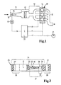
- FIG. 1 the intake tract of an internal combustion engine 10 is shown schematically. This consists of a venturi-shaped intake 11, an air filter 12, an intake manifold 13 leading to individual cylinders 14, an exhaust 15 the Guaranteed discharge of the burned gases.
- a throttle valve 16 is accommodated in the narrowest cross section 17 of the venturi tube.
- the throttle valve 16 according to FIG. 1 is in the fully open state shown.
- the throttle valve is started from an inlet 18 of the intake manifold flowed to what is indicated by an arrow.
- the position ⁇ of the throttle valve is set via a stepper motor 19.
- the Setting is carried out via a control unit 20, the various manipulated variables of the Intake tract evaluates the throttle valve position. For one, can the negative pressure p in the intake manifold can be measured.
- the Speed n of the internal combustion engine is determined, the speed signal can still be below With the help of a timer 21, which supplies the signal t, to determine the Acceleration n 'can be used.
- FIG. 2 shows an example of the structural design of the invention Throttle valve 16.
- the throttle valve is in one piece with a valve shaft 22 and Support ribs 23 made. This unit is injection molded into a flap frame 24, so that there is a throttle valve module 25.
- This can be used as a standard component can be installed in different pipe systems, including the scope three mounting flanges 26 with holes 27 for screws attached are.
- the throttle valve is shown in the closed position. Between a flap edge 28 and an inner wall 29 of the flap frame 24 has a residual cross section 30, which can be flowed through by the fluid.
- the flap can now be opened continuously whereby a by projecting the flap edges on the cross section 17 and opening cross-section bordered by the inner edge of the remaining cross-section always opens further.
- the maximum opening cross section 31 when fully open Flap is indicated in Figure 2, with the edge of the opening cross section in this Case is formed by the valve shaft 22.
- the fluid through which the fluid can flow effectively Cross section is calculated from the sum of the remaining cross section and the Opening cross section formed.
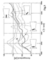
- the throttle valve can be used to increase the intake noise during the acceleration phase but can also be opened faster than necessary. This increases in these areas the intake noise of the internal combustion engine and enables this way an acoustic feedback for the driver.
- This mode is represented by curve b.
- the throttle valve is discontinuous in relation to Speed adjusted. In this way, the intake noise can be influenced as desired, whereby customer requests for a sound design can also be met.
Landscapes
- Engineering & Computer Science (AREA)
- Chemical & Material Sciences (AREA)
- Combustion & Propulsion (AREA)
- Mechanical Engineering (AREA)
- General Engineering & Computer Science (AREA)
- Control Of Throttle Valves Provided In The Intake System Or In The Exhaust System (AREA)
- Characterised By The Charging Evacuation (AREA)
Claims (6)
- Système de conduites (11, 12, 13) équipé d'un volet de réglage (16) dans le conduit d'admission d'un moteur à combustion interne, le volet de réglage étant disposé mobile en pivotement dans une section (17) qui fait partie du système de conduites pour le fluide à étrangler, le volet de réglage (16) étant disposé dans la région de l'entrée (18) du conduit d'admission d'un moteur à combustion interne, la région de l'entrée (18) du conduit d'admission étant la région d'embouchure,
caractérisé en ce que
dans la position de fermeture, le volet de réglage (16) laisse libre une section résiduelle (30) qui peut être traversée par le fluide à étrangler, la section résiduelle (30) entourant le volet de réglage (16) en anneau. - Système de conduites selon la revendication 1,
caractérisé en ce que
le volet de réglage (16) est disposé dans la section la plus étroite d'un tronçon de tube qui possède un profil de section en forme de Venturi, en particulier d'une tubulure d'admission (11). - Système de conduites selon une des revendications précédentes,
caractérisé en ce que
la section résiduelle (30) présente un contenu de surface qui représente entre 10 et 40 % de la surface totale de la section (17). - Procédé pour la commande d'un système de conduites selon une des revendications précédentes dans le conduit d'admission d'un moteur à combustion interne,
caractérisé en ce que
la position du volet est réglée en fonction du besoin quantitatif d'air comburant du moteur à combustion interne. - Procédé selon la revendication 4,
caractérisé en ce que
la grandeur réglée pour la position du volet est la vitesse de rotation du moteur à combustion interne. - Procédé selon une des revendications 4 et 5,
caractérisé en ce que
dans les états de fonctionnement du moteur à combustion interne dans lesquels le conducteur a besoin d'une rétroaction acoustique sur le moteur, la section d'ouverture (31) dégagée par le volet de réglage est choisie plus grande que cela ne serait nécessaire pour assurer une alimentation suffisante du moteur à combustion interne en air comburant.
Applications Claiming Priority (2)
| Application Number | Priority Date | Filing Date | Title |
|---|---|---|---|
| DE19928354A DE19928354A1 (de) | 1999-06-21 | 1999-06-21 | Leitungssystem mit Drosselklappe |
| DE19928354 | 1999-06-21 |
Publications (2)
| Publication Number | Publication Date |
|---|---|
| EP1063406A1 EP1063406A1 (fr) | 2000-12-27 |
| EP1063406B1 true EP1063406B1 (fr) | 2004-09-15 |
Family
ID=7912005
Family Applications (1)
| Application Number | Title | Priority Date | Filing Date |
|---|---|---|---|
| EP00111985A Expired - Lifetime EP1063406B1 (fr) | 1999-06-21 | 2000-06-19 | Système de tuyauterie avec un papillon |
Country Status (5)
| Country | Link |
|---|---|
| US (1) | US6427661B1 (fr) |
| EP (1) | EP1063406B1 (fr) |
| AT (1) | ATE276437T1 (fr) |
| DE (2) | DE19928354A1 (fr) |
| ES (1) | ES2226656T3 (fr) |
Cited By (2)
| Publication number | Priority date | Publication date | Assignee | Title |
|---|---|---|---|---|
| DE202006005140U1 (de) * | 2006-03-29 | 2007-08-09 | Mann + Hummel Gmbh | Schalldämpfungseinrichtung |
| DE202006011933U1 (de) * | 2006-08-02 | 2007-12-06 | Mann + Hummel Gmbh | Schalldämpfungseinrichtung |
Families Citing this family (7)
| Publication number | Priority date | Publication date | Assignee | Title |
|---|---|---|---|---|
| DE19918777A1 (de) * | 1999-04-24 | 2000-10-26 | Mann & Hummel Filter | Schaltklappenverband aus montagegespritzten Schaltklappen oder Klappenmodulen |
| US7464674B2 (en) * | 2006-06-16 | 2008-12-16 | Ford Global Technologies, Llc | Induction air acoustics management for internal combustion engine |
| US9341150B2 (en) * | 2012-11-06 | 2016-05-17 | GM Global Technology Operations LLC | Throttle control systems and methods for reducing induction noise |
| JP7065000B2 (ja) * | 2018-09-18 | 2022-05-11 | 日立Astemo株式会社 | 吸気装置 |
| CN113864089B (zh) * | 2020-06-30 | 2022-09-30 | 广州汽车集团股份有限公司 | 一种发动机进气歧管、进气系统及其控制方法 |
| US11614098B2 (en) | 2020-12-24 | 2023-03-28 | Dayco Ip Holdings, Llc | Devices for producing vacuum using the Venturi effect having a solid fletch |
| US11408380B2 (en) | 2020-12-24 | 2022-08-09 | Dayco Ip Holdings, Llc | Devices for producing vacuum using the Venturi effect having a hollow fletch |
Family Cites Families (20)
| Publication number | Priority date | Publication date | Assignee | Title |
|---|---|---|---|---|
| JPS56132457A (en) * | 1980-03-19 | 1981-10-16 | Hitachi Ltd | Fuel injector |
| JPS58122334A (ja) * | 1982-01-18 | 1983-07-21 | Toyota Motor Corp | デイ−ゼルエンジンの吸気絞り装置 |
| DE3244103A1 (de) * | 1982-11-29 | 1984-05-30 | Vdo Adolf Schindling Ag, 6000 Frankfurt | Drosselklappenstutzen |
| DE3608804A1 (de) * | 1986-03-15 | 1987-09-17 | Carduck F W Gmbh | Kanalschalldaempfer mit beweglichen schallabsorbierenden waenden |
| JPH0663460B2 (ja) * | 1986-06-02 | 1994-08-22 | 株式会社日立製作所 | 電動機駆動型絞弁用の絞弁組立体 |
| DE3620890A1 (de) * | 1986-06-21 | 1987-12-23 | Hella Kg Hueck & Co | Drosselklappenstutzen |
| US4759326A (en) * | 1986-07-10 | 1988-07-26 | Eaton Corporation | Method of controlling engine idle speed and air throttle therefor |
| DE69221651T2 (de) * | 1991-02-21 | 1997-12-11 | Yamaha Motor Co Ltd | Einlasssystem für eine Brennkraftmaschine |
| JPH04301174A (ja) * | 1991-03-28 | 1992-10-23 | Mazda Motor Corp | エンジンの吸気装置 |
| EP0714478B1 (fr) * | 1994-06-18 | 2000-04-26 | AB Elektronik GmbH | Dispositif de clapet de carburateur |
| JP3166546B2 (ja) * | 1994-08-17 | 2001-05-14 | トヨタ自動車株式会社 | 内燃機関 |
| JPH10103087A (ja) * | 1996-10-01 | 1998-04-21 | Mitsubishi Electric Corp | 制御弁装置 |
| DE69805883T2 (de) * | 1997-03-04 | 2003-02-13 | Nippon Soken, Inc. | Vorrichtung zum Verhindern von Durchströmgeräuschen bei Drosselklappen |
| JP3562235B2 (ja) * | 1997-07-03 | 2004-09-08 | 日産自動車株式会社 | 内燃機関の吸気騒音低減装置 |
| JP3341653B2 (ja) * | 1997-11-05 | 2002-11-05 | トヨタ自動車株式会社 | 吸気異音低減構造 |
| DE19812089C1 (de) * | 1998-03-19 | 1999-06-10 | Daimler Chrysler Ag | Ansaugsystem einer Mehrzylinder-Brennkraftmaschine mit Abgasrückführung |
| JPH11350981A (ja) * | 1998-06-11 | 1999-12-21 | Aisan Ind Co Ltd | スロットル弁制御装置 |
| FR2783283B1 (fr) * | 1998-09-14 | 2000-11-24 | Mark Iv Systemes Moteurs Sa | Ensemble integre collecteur d'admission/boitier papillon |
| DE19856521A1 (de) * | 1998-12-08 | 2000-06-15 | Mann & Hummel Filter | Luftleitung, insbesondere im Ansaugtrakt einer Brennkraftmaschine |
| US6189506B1 (en) * | 1999-08-06 | 2001-02-20 | Siemens Canada Limited | Throttle shaft rotation limiting device |
-
1999
- 1999-06-21 DE DE19928354A patent/DE19928354A1/de not_active Withdrawn
-
2000
- 2000-06-19 ES ES00111985T patent/ES2226656T3/es not_active Expired - Lifetime
- 2000-06-19 AT AT00111985T patent/ATE276437T1/de not_active IP Right Cessation
- 2000-06-19 EP EP00111985A patent/EP1063406B1/fr not_active Expired - Lifetime
- 2000-06-19 DE DE50007737T patent/DE50007737D1/de not_active Expired - Lifetime
- 2000-06-21 US US09/598,045 patent/US6427661B1/en not_active Expired - Lifetime
Cited By (2)
| Publication number | Priority date | Publication date | Assignee | Title |
|---|---|---|---|---|
| DE202006005140U1 (de) * | 2006-03-29 | 2007-08-09 | Mann + Hummel Gmbh | Schalldämpfungseinrichtung |
| DE202006011933U1 (de) * | 2006-08-02 | 2007-12-06 | Mann + Hummel Gmbh | Schalldämpfungseinrichtung |
Also Published As
| Publication number | Publication date |
|---|---|
| ES2226656T3 (es) | 2005-04-01 |
| EP1063406A1 (fr) | 2000-12-27 |
| ATE276437T1 (de) | 2004-10-15 |
| DE50007737D1 (de) | 2004-10-21 |
| DE19928354A1 (de) | 2000-12-28 |
| US6427661B1 (en) | 2002-08-06 |
Similar Documents
| Publication | Publication Date | Title |
|---|---|---|
| DE3521747C2 (de) | Ansaugsystem für eine Brennkraftmaschine | |
| DE102014114968B4 (de) | Regelvorrichtung für eine Verbrennungskraftmaschine | |
| EP1063406B1 (fr) | Système de tuyauterie avec un papillon | |
| DE10310487A1 (de) | Vorrichtung zur Geräuschübertragung | |
| EP2052893A2 (fr) | Réservoir d'eau pour un véhicule automobile et véhicule automobile doté d'un tel réservoir d'eau | |
| DE3435028C2 (fr) | ||
| EP0242797B1 (fr) | Silencieux d'aspiration, plus particulièrement pour moteurs à combustion interne | |
| DE3435701A1 (de) | Vorrichtung zur regelung der leerlaufdrehzahl | |
| EP0490104B1 (fr) | Procédé pour contrôler l'admission d'air pour moteur à combustion interne | |
| DE4216679A1 (de) | Einrichtung zur steuerung der einlassluft fuer einen verbrennungsmotor | |
| DE2444275C2 (de) | Steuerventil für eine Abgasrückführeinrichtung für Verbrennungsmotoren | |
| DE102007026416B4 (de) | Vorrichtung zur Beeinflussung des Ansauggeräusches einer Brennkraftmaschine | |
| EP0954686B1 (fr) | Tubulure d'aspiration pour la regulation de la consommation d'air dans le systeme d'aspiration d'un moteur a combustion interne | |
| DE3624248C2 (fr) | ||
| DE20120470U1 (de) | Schalldämpfungseinrichtung | |
| EP3737919B1 (fr) | Dispositif de mesure permettant de déterminer un paramètre d'un fluide s'écoulant à travers un canal d'écoulement de fluide et canal d'écoulement de fluide avec un tel dispositif de mesure | |
| DE2451148C3 (de) | Abgasrückführeinrichtung bei Verbrennungsmotoren | |
| DE3227722A1 (de) | Abgasrueckfuehrsystem bei einer brennkraftmaschine, insbesondere in einem kraftfahrzeug | |
| DE102017210793A1 (de) | Kühlaggregat, Steuereinheit und Verfahren zum Steuern einer Kondensatmenge in einem Kühlaggregat | |
| DE10065365B4 (de) | Ansaugsystem | |
| DE19813747A1 (de) | Ansaugvorrichtung eines Verbrennungsmotors | |
| DE102008050139A1 (de) | Verfahren zum Vermeiden von Staulufteintragung in die Fahrgastzelle eines Kraftfahrzeugs | |
| EP1429081B1 (fr) | Système de ventilation pour la ventilation d'un local | |
| DE102006025889A1 (de) | Saugkanal für die Verbrennungsluft einer Brennkraftmaschine | |
| DE102005054991A1 (de) | Abgasanlage und Verfahren zum Betreiben einer Abgasanlage |
Legal Events
| Date | Code | Title | Description |
|---|---|---|---|
| EUG | Se: european patent has lapsed | ||
| PUAI | Public reference made under article 153(3) epc to a published international application that has entered the european phase |
Free format text: ORIGINAL CODE: 0009012 |
|
| AK | Designated contracting states |
Kind code of ref document: A1 Designated state(s): AT BE CH CY DE DK ES FI FR GB GR IE IT LI LU MC NL PT SE |
|
| AX | Request for extension of the european patent |
Free format text: AL;LT;LV;MK;RO;SI |
|
| 17P | Request for examination filed |
Effective date: 20010118 |
|
| AKX | Designation fees paid |
Free format text: AT BE CH CY DE DK ES FI FR GB GR IE IT LI LU MC NL PT SE |
|
| 17Q | First examination report despatched |
Effective date: 20030213 |
|
| RAP1 | Party data changed (applicant data changed or rights of an application transferred) |
Owner name: MANN + HUMMEL GMBH |
|
| GRAP | Despatch of communication of intention to grant a patent |
Free format text: ORIGINAL CODE: EPIDOSNIGR1 |
|
| GRAS | Grant fee paid |
Free format text: ORIGINAL CODE: EPIDOSNIGR3 |
|
| GRAA | (expected) grant |
Free format text: ORIGINAL CODE: 0009210 |
|
| AK | Designated contracting states |
Kind code of ref document: B1 Designated state(s): AT BE CH CY DE DK ES FI FR GB GR IE IT LI LU MC NL PT SE |
|
| PG25 | Lapsed in a contracting state [announced via postgrant information from national office to epo] |
Ref country code: IT Free format text: LAPSE BECAUSE OF FAILURE TO SUBMIT A TRANSLATION OF THE DESCRIPTION OR TO PAY THE FEE WITHIN THE PRE;WARNING: LAPSES OF ITALIAN PATENTS WITH EFFECTIVE DATE BEFORE 2007 MAY HAVE OCCURRED AT ANY TIME BEFORE 2007. THE CORRECT EFFECTIVE DATE MAY BE DIFFERENT FROM THE ONE RECORDED.SCRIBED TIME-LIMIT Effective date: 20040915 Ref country code: FI Free format text: LAPSE BECAUSE OF FAILURE TO SUBMIT A TRANSLATION OF THE DESCRIPTION OR TO PAY THE FEE WITHIN THE PRESCRIBED TIME-LIMIT Effective date: 20040915 Ref country code: IE Free format text: LAPSE BECAUSE OF FAILURE TO SUBMIT A TRANSLATION OF THE DESCRIPTION OR TO PAY THE FEE WITHIN THE PRESCRIBED TIME-LIMIT Effective date: 20040915 Ref country code: NL Free format text: LAPSE BECAUSE OF FAILURE TO SUBMIT A TRANSLATION OF THE DESCRIPTION OR TO PAY THE FEE WITHIN THE PRESCRIBED TIME-LIMIT Effective date: 20040915 |
|
| REG | Reference to a national code |
Ref country code: CH Ref legal event code: EP Ref country code: GB Ref legal event code: FG4D Free format text: NOT ENGLISH |
|
| GBT | Gb: translation of ep patent filed (gb section 77(6)(a)/1977) |
Effective date: 20040915 |
|
| REG | Reference to a national code |
Ref country code: IE Ref legal event code: FG4D Free format text: GERMAN |
|
| REF | Corresponds to: |
Ref document number: 50007737 Country of ref document: DE Date of ref document: 20041021 Kind code of ref document: P |
|
| REG | Reference to a national code |
Ref country code: SE Ref legal event code: TRGR |
|
| PG25 | Lapsed in a contracting state [announced via postgrant information from national office to epo] |
Ref country code: DK Free format text: LAPSE BECAUSE OF FAILURE TO SUBMIT A TRANSLATION OF THE DESCRIPTION OR TO PAY THE FEE WITHIN THE PRESCRIBED TIME-LIMIT Effective date: 20041215 Ref country code: GR Free format text: LAPSE BECAUSE OF FAILURE TO SUBMIT A TRANSLATION OF THE DESCRIPTION OR TO PAY THE FEE WITHIN THE PRESCRIBED TIME-LIMIT Effective date: 20041215 |
|
| NLV1 | Nl: lapsed or annulled due to failure to fulfill the requirements of art. 29p and 29m of the patents act | ||
| REG | Reference to a national code |
Ref country code: ES Ref legal event code: FG2A Ref document number: 2226656 Country of ref document: ES Kind code of ref document: T3 |
|
| REG | Reference to a national code |
Ref country code: IE Ref legal event code: FD4D |
|
| ET | Fr: translation filed | ||
| PG25 | Lapsed in a contracting state [announced via postgrant information from national office to epo] |
Ref country code: LU Free format text: LAPSE BECAUSE OF NON-PAYMENT OF DUE FEES Effective date: 20050619 Ref country code: AT Free format text: LAPSE BECAUSE OF NON-PAYMENT OF DUE FEES Effective date: 20050619 Ref country code: CY Free format text: LAPSE BECAUSE OF FAILURE TO SUBMIT A TRANSLATION OF THE DESCRIPTION OR TO PAY THE FEE WITHIN THE PRESCRIBED TIME-LIMIT Effective date: 20050619 |
|
| PG25 | Lapsed in a contracting state [announced via postgrant information from national office to epo] |
Ref country code: LI Free format text: LAPSE BECAUSE OF NON-PAYMENT OF DUE FEES Effective date: 20050630 Ref country code: BE Free format text: LAPSE BECAUSE OF NON-PAYMENT OF DUE FEES Effective date: 20050630 Ref country code: CH Free format text: LAPSE BECAUSE OF NON-PAYMENT OF DUE FEES Effective date: 20050630 Ref country code: MC Free format text: LAPSE BECAUSE OF NON-PAYMENT OF DUE FEES Effective date: 20050630 |
|
| PLBE | No opposition filed within time limit |
Free format text: ORIGINAL CODE: 0009261 |
|
| STAA | Information on the status of an ep patent application or granted ep patent |
Free format text: STATUS: NO OPPOSITION FILED WITHIN TIME LIMIT |
|
| 26N | No opposition filed |
Effective date: 20050616 |
|
| REG | Reference to a national code |
Ref country code: CH Ref legal event code: PL |
|
| PGFP | Annual fee paid to national office [announced via postgrant information from national office to epo] |
Ref country code: SE Payment date: 20060614 Year of fee payment: 7 |
|
| PGFP | Annual fee paid to national office [announced via postgrant information from national office to epo] |
Ref country code: GB Payment date: 20060615 Year of fee payment: 7 |
|
| PGFP | Annual fee paid to national office [announced via postgrant information from national office to epo] |
Ref country code: ES Payment date: 20060629 Year of fee payment: 7 |
|
| BERE | Be: lapsed |
Owner name: *MANN + HUMMEL G.M.B.H. Effective date: 20050630 |
|
| PG25 | Lapsed in a contracting state [announced via postgrant information from national office to epo] |
Ref country code: PT Free format text: LAPSE BECAUSE OF NON-PAYMENT OF DUE FEES Effective date: 20050215 |
|
| EUG | Se: european patent has lapsed | ||
| GBPC | Gb: european patent ceased through non-payment of renewal fee |
Effective date: 20070619 |
|
| PG25 | Lapsed in a contracting state [announced via postgrant information from national office to epo] |
Ref country code: GB Free format text: LAPSE BECAUSE OF NON-PAYMENT OF DUE FEES Effective date: 20070619 |
|
| PG25 | Lapsed in a contracting state [announced via postgrant information from national office to epo] |
Ref country code: SE Free format text: LAPSE BECAUSE OF NON-PAYMENT OF DUE FEES Effective date: 20070620 |
|
| REG | Reference to a national code |
Ref country code: ES Ref legal event code: FD2A Effective date: 20070620 |
|
| PG25 | Lapsed in a contracting state [announced via postgrant information from national office to epo] |
Ref country code: ES Free format text: LAPSE BECAUSE OF NON-PAYMENT OF DUE FEES Effective date: 20070620 |
|
| PGFP | Annual fee paid to national office [announced via postgrant information from national office to epo] |
Ref country code: FR Payment date: 20130703 Year of fee payment: 14 |
|
| REG | Reference to a national code |
Ref country code: FR Ref legal event code: ST Effective date: 20150227 |
|
| PG25 | Lapsed in a contracting state [announced via postgrant information from national office to epo] |
Ref country code: FR Free format text: LAPSE BECAUSE OF NON-PAYMENT OF DUE FEES Effective date: 20140630 |
|
| REG | Reference to a national code |
Ref country code: DE Ref legal event code: R081 Ref document number: 50007737 Country of ref document: DE Owner name: MANN+HUMMEL GMBH, DE Free format text: FORMER OWNER: MANN + HUMMEL GMBH, 71638 LUDWIGSBURG, DE |
|
| PGFP | Annual fee paid to national office [announced via postgrant information from national office to epo] |
Ref country code: DE Payment date: 20190619 Year of fee payment: 20 |
|
| REG | Reference to a national code |
Ref country code: DE Ref legal event code: R071 Ref document number: 50007737 Country of ref document: DE |