EP1065164A2 - Limiteur de vitesse - Google Patents
Limiteur de vitesse Download PDFInfo
- Publication number
- EP1065164A2 EP1065164A2 EP00113417A EP00113417A EP1065164A2 EP 1065164 A2 EP1065164 A2 EP 1065164A2 EP 00113417 A EP00113417 A EP 00113417A EP 00113417 A EP00113417 A EP 00113417A EP 1065164 A2 EP1065164 A2 EP 1065164A2
- Authority
- EP
- European Patent Office
- Prior art keywords
- car
- wheel
- trigger
- speed
- rope
- Prior art date
- Legal status (The legal status is an assumption and is not a legal conclusion. Google has not performed a legal analysis and makes no representation as to the accuracy of the status listed.)
- Granted
Links
- 230000001960 triggered effect Effects 0.000 claims description 5
- 230000001133 acceleration Effects 0.000 description 6
- 230000000452 restraining effect Effects 0.000 description 4
- 230000007547 defect Effects 0.000 description 2
- 239000000725 suspension Substances 0.000 description 2
- 230000000903 blocking effect Effects 0.000 description 1
- 230000006835 compression Effects 0.000 description 1
- 238000007906 compression Methods 0.000 description 1
- 238000006073 displacement reaction Methods 0.000 description 1
- 230000014759 maintenance of location Effects 0.000 description 1
- 238000000034 method Methods 0.000 description 1
Images

Classifications
-
- B—PERFORMING OPERATIONS; TRANSPORTING
- B66—HOISTING; LIFTING; HAULING
- B66B—ELEVATORS; ESCALATORS OR MOVING WALKWAYS
- B66B5/00—Applications of checking, fault-correcting, or safety devices in elevators
- B66B5/02—Applications of checking, fault-correcting, or safety devices in elevators responsive to abnormal operating conditions
- B66B5/04—Applications of checking, fault-correcting, or safety devices in elevators responsive to abnormal operating conditions for detecting excessive speed
- B66B5/044—Mechanical overspeed governors
- B66B5/046—Mechanical overspeed governors of the pendulum or rocker arm type
-
- B—PERFORMING OPERATIONS; TRANSPORTING
- B66—HOISTING; LIFTING; HAULING
- B66B—ELEVATORS; ESCALATORS OR MOVING WALKWAYS
- B66B5/00—Applications of checking, fault-correcting, or safety devices in elevators
- B66B5/02—Applications of checking, fault-correcting, or safety devices in elevators responsive to abnormal operating conditions
- B66B5/04—Applications of checking, fault-correcting, or safety devices in elevators responsive to abnormal operating conditions for detecting excessive speed
Definitions
- the invention relates to a speed limiter for elevator systems and takes claim the priority of the German patent application 199 29 340.6-22 to which reference is made to the content.
- Cable-operated elevator systems generally consist of one on the car head attached wire rope group, which over one or more pulleys in the area of Elevator shaft head guided with counter loads arranged in a guide rail are connected, wherein one of the deflection rollers is connected to a drive.
- the counter loads are designed so that they are half the permissible maximum load compensate for the car including the car weight.
- a safety device in the area of the elevator car usually consists of wedge pieces arranged on the car, which with guide rails work together.
- a speed limiter with a trigger device for triggering the safety gear used.
- the triggering device operates unlocking the catch wedges.
- the wedges slide into the Gap between the car and the guide rail, the acceleration force of the Car to fix the catching wedges and to brake the car leads. So the car can be independent of the elevator drive or the rope suspension be braked safely.
- the control cable runs from the speed limiter wheel to the shaft pit in the it is steered back upwards via a tension pulley and with its end is in turn attached to the trigger device on the car.
- the tension pulley is slidably or pivotably mounted and connected with a tension weight, so that the regulator cable maintains a certain minimum tension, even if this extends over a certain period of use. This ensures one safe running of the wire rope in the respective wheel grooves and thus a reliable one Trigger the safety gear via the governor wheel.
- the speed limiter described thus represents a satisfactory one Trigger device for the safety gear of a car to avoid excessive downward acceleration, a safeguard against however, there is no excessive upward acceleration. But since that Counterweight for the car designed for half the maximum load of the car is, it can happen that the car is under half with partial load Maximum load is accelerated in the upward direction. The majority of the known elevator systems do not have a safety system for this accident.
- the invention is therefore based on the object of a triggering device for the Safety gear of a car to create a safe triggering when over-accelerated of the car in the upward direction.
- the object is achieved by a device according to claim 1.
- the clamping mechanism on the car side on the speed limiter wheel reliably prevents the regulator cable from being pushed over the governor wheel, by triggering the clamping mechanism simultaneously with the governor wheel and fixed the rope section to the governor wheel and clamping mechanism.
- control cable can also be used in this combination to trigger the safety gear in the event of excessive upward acceleration of the Insert the car safely.
- the speed limiter wheel locks when the car is over speeding upwards. whereby the car passes over the lower idler pulley through its Upward movement places a tension on the regulator rope. Because with blocking of the governor wheel simultaneously the clamping mechanism between the car and If the governor rope engages the governor rope, the governor rope is pulled by the car driven into the kite groove of the governor wheel. Because of the restraint on the lower tensioning roller, the retaining force in the wedge groove of the Speed limiter wheel locked regulator cable immediately on the release act on the safety gear on the car, causing the car to brake becomes.
- the retaining device on the lower tensioning roller preferably consists of a Retaining arm, which is mounted on a lever arm of the tension pulley and has on one side a sleeve slidably mounted on a rod. In the event of a jerky displacement of the lever arm then wedges the liner in the support rod so that the normally pivotable lever arm of the tension pulley is locked by the restraining arm and prevents the rope from yielding.
- the clamping mechanism between the governor wheel and the car can be activated with the trigger mechanism the speed limiter wheel via a release rod be connected so that a triggering of the mechanism of the speed limiter wheel mechanically implemented immediately in a triggering of the clamping mechanism becomes.
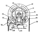
- the speed limiter consists of a governor wheel 10, with a V-shaped or undercut wedge groove 20 in which a regulator cable 30 is arranged.
- the Limiter wheel 10 has a trigger mechanism for the speed limit on. This has a swinging two-armed pendulum 43, which has on one arm a roller 46, which has four elevations Cam track 12 of the governor wheel 10 runs along.
- the other arm of the pendulum 43 is provided with a tip that is not in the catch cams 13 of the Limiter wheel 10 engages as the roller 46 abuts the cam track 12.
- a compression spring 42 which acts on the pendulum 43.
- the Regulator rope 30 is either an endless rope or is at two points in the car (Not shown) attached, so that a circulating flow of power over the regulator rope comes about.
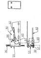
- On the car side there is a clamping mechanism below the limiter wheel 10 50 arranged, the one eccentrically mounted on a pin 66 Brake shoe 65 with its braking surface 67 via an outlet rod 60 with the
- the trigger mechanism of the governor wheel 10 is connected to the cable 30 and presses the pressure plate 55.
- the rope is located in the rope guide 57.
- the regulator cable 30 acts on the safety gear via the attachment to the car of the car (not shown), which is both by locking the control cable 30th can be triggered when driving upwards as well as when driving downwards.
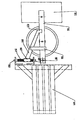
- the regulator rope is over a tension roller 70 is guided in the shaft pit of the elevator shaft, as in FIG. 2 shown.
- the tensioning roller 70 is pivotable about a bolt 80 on a holding arm 90 stored.
- the pretension of the tensioning roller 70 is determined by a at the end of the lever arm 90 arranged weight ensures 110.
- the lever arm 90 is at its other End over the bolt 80 and a carrier 120 with a guide rail 130 of the Elevator shaft connected.
- the carrier 120 has a substantially vertical orientation above the lever arm 90 threaded rod 140 arranged on the lever arm, on which a bushing 150 is arranged which is arranged on the lever arm 90 via a retaining arm 160 Running shoe 170 is connected.
- the restraining arm 160 which functions as the tensioning roller 70 during normal operation not hindered by a free running shoe 170 and liner 150 Allows pivoting of the lever arm 90, wedged by the jerky upward movement the lever arm 90 with the sleeve 150 in the threaded rod 140, whereby the restraining force can act on the lever arm 90 via the running shoe 170.
Landscapes
- Engineering & Computer Science (AREA)
- Mechanical Engineering (AREA)
- Maintenance And Inspection Apparatuses For Elevators (AREA)
- Electric Cable Installation (AREA)
- Jib Cranes (AREA)
- Lift-Guide Devices, And Elevator Ropes And Cables (AREA)
Applications Claiming Priority (2)
| Application Number | Priority Date | Filing Date | Title |
|---|---|---|---|
| DE19929340A DE19929340A1 (de) | 1998-12-07 | 1999-06-26 | Geschwindigkeitsbegrenzer |
| DE19929340 | 1999-06-26 |
Publications (3)
| Publication Number | Publication Date |
|---|---|
| EP1065164A2 true EP1065164A2 (fr) | 2001-01-03 |
| EP1065164A3 EP1065164A3 (fr) | 2004-04-14 |
| EP1065164B1 EP1065164B1 (fr) | 2007-02-14 |
Family
ID=7912658
Family Applications (1)
| Application Number | Title | Priority Date | Filing Date |
|---|---|---|---|
| EP00113417A Expired - Lifetime EP1065164B1 (fr) | 1999-06-26 | 2000-06-23 | Dispositif de tension pour un câble de limiteur de vitesse |
Country Status (3)
| Country | Link |
|---|---|
| EP (1) | EP1065164B1 (fr) |
| AT (1) | ATE353848T1 (fr) |
| DE (1) | DE50014051D1 (fr) |
Family Cites Families (3)
| Publication number | Priority date | Publication date | Assignee | Title |
|---|---|---|---|---|
| CH572863A5 (fr) * | 1974-06-24 | 1976-02-27 | Inventio Ag | |
| US5299661A (en) * | 1992-11-03 | 1994-04-05 | Otis Elevator Company | Mechanical overspeed safety device |
| US5617933A (en) * | 1995-06-13 | 1997-04-08 | Otis Elevator Company | Bi-directional elevator governor |
-
2000
- 2000-06-23 DE DE50014051T patent/DE50014051D1/de not_active Expired - Lifetime
- 2000-06-23 AT AT00113417T patent/ATE353848T1/de not_active IP Right Cessation
- 2000-06-23 EP EP00113417A patent/EP1065164B1/fr not_active Expired - Lifetime
Also Published As
| Publication number | Publication date |
|---|---|
| EP1065164A3 (fr) | 2004-04-14 |
| ATE353848T1 (de) | 2007-03-15 |
| DE50014051D1 (de) | 2007-03-29 |
| EP1065164B1 (fr) | 2007-02-14 |
Similar Documents
| Publication | Publication Date | Title |
|---|---|---|
| DE2753445C2 (fr) | ||
| EP1213247A1 (fr) | Installation et méthode pour débloquer un frein de secours | |
| EP0565516A1 (fr) | Ascenseur | |
| EP0440839B2 (fr) | Dispositif pour empêcher des déplacements involontaires des ascenseurs | |
| EP2125389B1 (fr) | Ascenseur | |
| DE60201883T2 (de) | Notbremsvorrichtung für ein kabelgezogenes oder aufgehängtes fahrzeug und fahrzeug mit einer notbremsvorrichtung | |
| DE4211009A1 (de) | Gurtstraffer für Fahrzeug-Sicherheitsgurtsysteme | |
| DE102012016336A1 (de) | Geschwindigkeitsbegrenzer für ein Aufzugsystem | |
| EP0787676A1 (fr) | Dispositif de sécurité | |
| WO1997017107A1 (fr) | Appareil de levage et d'abaissement a elingue | |
| DE2400198A1 (de) | Sicherheitsbremse | |
| CH633495A5 (de) | Vertikale foerdereinrichtung mit fangvorrichtung. | |
| DE4000831C2 (fr) | ||
| DE19643455A1 (de) | Steigvorrichtung | |
| EP1065164B1 (fr) | Dispositif de tension pour un câble de limiteur de vitesse | |
| EP3927641B1 (fr) | Système de déclenchement pour un dispositif d'arrêt, installation d'ascenseur et procédé pour faire fonctionner une installation d'ascenseur | |
| DE19929340A1 (de) | Geschwindigkeitsbegrenzer | |
| DE1531103A1 (de) | Gleitfangvorrichtung an Aufzuegen | |
| DE29912544U1 (de) | Geschwindigkeitsbegrenzer | |
| EP0161287A1 (fr) | Dispositif parachute notamment pour cabines d'ascenseur | |
| DE4313335C2 (de) | Schlitten mit Fallbremse | |
| EP3020674B1 (fr) | Ascenseur de service | |
| DE1295150B (de) | Aufzug mit einer Sperreinrichtung an der Unterseilrolle | |
| EP0806394A1 (fr) | Dispositif de sécurité pour ascenseur | |
| EP0611710A2 (fr) | Dispositif pour laisser libre la piste du trajet de convoyage de l'installation d'un transporteur aérien en cas d'alarme |
Legal Events
| Date | Code | Title | Description |
|---|---|---|---|
| PUAI | Public reference made under article 153(3) epc to a published international application that has entered the european phase |
Free format text: ORIGINAL CODE: 0009012 |
|
| AK | Designated contracting states |
Kind code of ref document: A2 Designated state(s): AT BE CH CY DE DK ES FI FR GB GR IE IT LI LU MC NL PT SE |
|
| AX | Request for extension of the european patent |
Free format text: AL;LT;LV;MK;RO;SI |
|
| PUAL | Search report despatched |
Free format text: ORIGINAL CODE: 0009013 |
|
| AK | Designated contracting states |
Kind code of ref document: A3 Designated state(s): AT BE CH CY DE DK ES FI FR GB GR IE IT LI LU MC NL PT SE |
|
| AX | Request for extension of the european patent |
Extension state: AL LT LV MK RO SI |
|
| 17P | Request for examination filed |
Effective date: 20041014 |
|
| AKX | Designation fees paid |
Designated state(s): AT BE CH CY DE DK ES FI FR GB GR IE IT LI LU MC NL PT SE |
|
| RAX | Requested extension states of the european patent have changed |
Extension state: RO Payment date: 20041116 |
|
| 17Q | First examination report despatched |
Effective date: 20050603 |
|
| GRAP | Despatch of communication of intention to grant a patent |
Free format text: ORIGINAL CODE: EPIDOSNIGR1 |
|
| RTI1 | Title (correction) |
Free format text: TENSIONING DEVICE FOR A GOVERNOR ROPE OF AN OVERSPEED GOVERNOR |
|
| GRAS | Grant fee paid |
Free format text: ORIGINAL CODE: EPIDOSNIGR3 |
|
| RAP1 | Party data changed (applicant data changed or rights of an application transferred) |
Owner name: BODE COMPONENTS GMBH |
|
| GRAA | (expected) grant |
Free format text: ORIGINAL CODE: 0009210 |
|
| AK | Designated contracting states |
Kind code of ref document: B1 Designated state(s): AT BE CH CY DE DK ES FI FR GB GR IE IT LI LU MC NL PT SE |
|
| AX | Request for extension of the european patent |
Extension state: RO |
|
| PG25 | Lapsed in a contracting state [announced via postgrant information from national office to epo] |
Ref country code: FI Free format text: LAPSE BECAUSE OF FAILURE TO SUBMIT A TRANSLATION OF THE DESCRIPTION OR TO PAY THE FEE WITHIN THE PRESCRIBED TIME-LIMIT Effective date: 20070214 Ref country code: DK Free format text: LAPSE BECAUSE OF FAILURE TO SUBMIT A TRANSLATION OF THE DESCRIPTION OR TO PAY THE FEE WITHIN THE PRESCRIBED TIME-LIMIT Effective date: 20070214 Ref country code: NL Free format text: LAPSE BECAUSE OF FAILURE TO SUBMIT A TRANSLATION OF THE DESCRIPTION OR TO PAY THE FEE WITHIN THE PRESCRIBED TIME-LIMIT Effective date: 20070214 Ref country code: IE Free format text: LAPSE BECAUSE OF FAILURE TO SUBMIT A TRANSLATION OF THE DESCRIPTION OR TO PAY THE FEE WITHIN THE PRESCRIBED TIME-LIMIT Effective date: 20070214 |
|
| REG | Reference to a national code |
Ref country code: GB Ref legal event code: FG4D Free format text: NOT ENGLISH |
|
| REG | Reference to a national code |
Ref country code: CH Ref legal event code: EP |
|
| REF | Corresponds to: |
Ref document number: 50014051 Country of ref document: DE Date of ref document: 20070329 Kind code of ref document: P |
|
| REG | Reference to a national code |
Ref country code: IE Ref legal event code: FG4D Free format text: LANGUAGE OF EP DOCUMENT: GERMAN |
|
| PG25 | Lapsed in a contracting state [announced via postgrant information from national office to epo] |
Ref country code: SE Free format text: LAPSE BECAUSE OF FAILURE TO SUBMIT A TRANSLATION OF THE DESCRIPTION OR TO PAY THE FEE WITHIN THE PRESCRIBED TIME-LIMIT Effective date: 20070514 |
|
| PG25 | Lapsed in a contracting state [announced via postgrant information from national office to epo] |
Ref country code: ES Free format text: LAPSE BECAUSE OF FAILURE TO SUBMIT A TRANSLATION OF THE DESCRIPTION OR TO PAY THE FEE WITHIN THE PRESCRIBED TIME-LIMIT Effective date: 20070525 |
|
| PG25 | Lapsed in a contracting state [announced via postgrant information from national office to epo] |
Ref country code: PT Free format text: LAPSE BECAUSE OF FAILURE TO SUBMIT A TRANSLATION OF THE DESCRIPTION OR TO PAY THE FEE WITHIN THE PRESCRIBED TIME-LIMIT Effective date: 20070716 |
|
| NLV1 | Nl: lapsed or annulled due to failure to fulfill the requirements of art. 29p and 29m of the patents act | ||
| GBV | Gb: ep patent (uk) treated as always having been void in accordance with gb section 77(7)/1977 [no translation filed] |
Effective date: 20070214 |
|
| REG | Reference to a national code |
Ref country code: IE Ref legal event code: FD4D |
|
| EN | Fr: translation not filed | ||
| PG25 | Lapsed in a contracting state [announced via postgrant information from national office to epo] |
Ref country code: GB Free format text: LAPSE BECAUSE OF FAILURE TO SUBMIT A TRANSLATION OF THE DESCRIPTION OR TO PAY THE FEE WITHIN THE PRESCRIBED TIME-LIMIT Effective date: 20070214 |
|
| PLBE | No opposition filed within time limit |
Free format text: ORIGINAL CODE: 0009261 |
|
| STAA | Information on the status of an ep patent application or granted ep patent |
Free format text: STATUS: NO OPPOSITION FILED WITHIN TIME LIMIT |
|
| BERE | Be: lapsed |
Owner name: BODE COMPONENTS G.M.B.H. Effective date: 20070630 |
|
| 26N | No opposition filed |
Effective date: 20071115 |
|
| PG25 | Lapsed in a contracting state [announced via postgrant information from national office to epo] |
Ref country code: MC Free format text: LAPSE BECAUSE OF NON-PAYMENT OF DUE FEES Effective date: 20070630 |
|
| REG | Reference to a national code |
Ref country code: CH Ref legal event code: PL |
|
| PG25 | Lapsed in a contracting state [announced via postgrant information from national office to epo] |
Ref country code: BE Free format text: LAPSE BECAUSE OF NON-PAYMENT OF DUE FEES Effective date: 20070630 |
|
| PG25 | Lapsed in a contracting state [announced via postgrant information from national office to epo] |
Ref country code: GR Free format text: LAPSE BECAUSE OF FAILURE TO SUBMIT A TRANSLATION OF THE DESCRIPTION OR TO PAY THE FEE WITHIN THE PRESCRIBED TIME-LIMIT Effective date: 20070515 Ref country code: CH Free format text: LAPSE BECAUSE OF NON-PAYMENT OF DUE FEES Effective date: 20070630 Ref country code: FR Free format text: LAPSE BECAUSE OF FAILURE TO SUBMIT A TRANSLATION OF THE DESCRIPTION OR TO PAY THE FEE WITHIN THE PRESCRIBED TIME-LIMIT Effective date: 20071005 Ref country code: IT Free format text: LAPSE BECAUSE OF FAILURE TO SUBMIT A TRANSLATION OF THE DESCRIPTION OR TO PAY THE FEE WITHIN THE PRESCRIBED TIME-LIMIT Effective date: 20070214 Ref country code: LI Free format text: LAPSE BECAUSE OF NON-PAYMENT OF DUE FEES Effective date: 20070630 |
|
| PG25 | Lapsed in a contracting state [announced via postgrant information from national office to epo] |
Ref country code: AT Free format text: LAPSE BECAUSE OF NON-PAYMENT OF DUE FEES Effective date: 20070623 |
|
| PG25 | Lapsed in a contracting state [announced via postgrant information from national office to epo] |
Ref country code: FR Free format text: LAPSE BECAUSE OF FAILURE TO SUBMIT A TRANSLATION OF THE DESCRIPTION OR TO PAY THE FEE WITHIN THE PRESCRIBED TIME-LIMIT Effective date: 20070214 |
|
| PG25 | Lapsed in a contracting state [announced via postgrant information from national office to epo] |
Ref country code: CY Free format text: LAPSE BECAUSE OF FAILURE TO SUBMIT A TRANSLATION OF THE DESCRIPTION OR TO PAY THE FEE WITHIN THE PRESCRIBED TIME-LIMIT Effective date: 20070214 |
|
| PG25 | Lapsed in a contracting state [announced via postgrant information from national office to epo] |
Ref country code: LU Free format text: LAPSE BECAUSE OF NON-PAYMENT OF DUE FEES Effective date: 20070623 |
|
| PGFP | Annual fee paid to national office [announced via postgrant information from national office to epo] |
Ref country code: DE Payment date: 20140724 Year of fee payment: 15 |
|
| REG | Reference to a national code |
Ref country code: DE Ref legal event code: R119 Ref document number: 50014051 Country of ref document: DE |
|
| PG25 | Lapsed in a contracting state [announced via postgrant information from national office to epo] |
Ref country code: DE Free format text: LAPSE BECAUSE OF NON-PAYMENT OF DUE FEES Effective date: 20160101 |