EP1065452A2 - Kältekreislauf mit Heissgasnebenleitungsanordnung - Google Patents
Kältekreislauf mit Heissgasnebenleitungsanordnung Download PDFInfo
- Publication number
- EP1065452A2 EP1065452A2 EP00111988A EP00111988A EP1065452A2 EP 1065452 A2 EP1065452 A2 EP 1065452A2 EP 00111988 A EP00111988 A EP 00111988A EP 00111988 A EP00111988 A EP 00111988A EP 1065452 A2 EP1065452 A2 EP 1065452A2
- Authority
- EP
- European Patent Office
- Prior art keywords
- refrigerant
- pressure
- compressor
- cycle system
- heating mode
- Prior art date
- Legal status (The legal status is an assumption and is not a legal conclusion. Google has not performed a legal analysis and makes no representation as to the accuracy of the status listed.)
- Granted
Links
Images




Classifications
-
- F—MECHANICAL ENGINEERING; LIGHTING; HEATING; WEAPONS; BLASTING
- F25—REFRIGERATION OR COOLING; COMBINED HEATING AND REFRIGERATION SYSTEMS; HEAT PUMP SYSTEMS; MANUFACTURE OR STORAGE OF ICE; LIQUEFACTION SOLIDIFICATION OF GASES
- F25B—REFRIGERATION MACHINES, PLANTS OR SYSTEMS; COMBINED HEATING AND REFRIGERATION SYSTEMS; HEAT PUMP SYSTEMS
- F25B49/00—Arrangement or mounting of control or safety devices
- F25B49/005—Arrangement or mounting of control or safety devices of safety devices
-
- B—PERFORMING OPERATIONS; TRANSPORTING
- B60—VEHICLES IN GENERAL
- B60H—ARRANGEMENTS OF HEATING, COOLING, VENTILATING OR OTHER AIR-TREATING DEVICES SPECIALLY ADAPTED FOR PASSENGER OR GOODS SPACES OF VEHICLES
- B60H1/00—Heating, cooling or ventilating devices
- B60H1/32—Cooling devices
- B60H1/3204—Cooling devices using compression
- B60H1/3225—Cooling devices using compression characterised by safety arrangements, e.g. compressor anti-seizure means or by signalling devices
-
- F—MECHANICAL ENGINEERING; LIGHTING; HEATING; WEAPONS; BLASTING
- F25—REFRIGERATION OR COOLING; COMBINED HEATING AND REFRIGERATION SYSTEMS; HEAT PUMP SYSTEMS; MANUFACTURE OR STORAGE OF ICE; LIQUEFACTION SOLIDIFICATION OF GASES
- F25B—REFRIGERATION MACHINES, PLANTS OR SYSTEMS; COMBINED HEATING AND REFRIGERATION SYSTEMS; HEAT PUMP SYSTEMS
- F25B41/00—Fluid-circulation arrangements
- F25B41/20—Disposition of valves, e.g. of on-off valves or flow control valves
- F25B41/24—Arrangement of shut-off valves for disconnecting a part of the refrigerant cycle, e.g. an outdoor part
-
- F—MECHANICAL ENGINEERING; LIGHTING; HEATING; WEAPONS; BLASTING
- F25—REFRIGERATION OR COOLING; COMBINED HEATING AND REFRIGERATION SYSTEMS; HEAT PUMP SYSTEMS; MANUFACTURE OR STORAGE OF ICE; LIQUEFACTION SOLIDIFICATION OF GASES
- F25B—REFRIGERATION MACHINES, PLANTS OR SYSTEMS; COMBINED HEATING AND REFRIGERATION SYSTEMS; HEAT PUMP SYSTEMS
- F25B2400/00—Component parts or details not otherwise provided for in this subclass
- F25B2400/04—Refrigeration circuit bypassing means
- F25B2400/0403—Refrigeration circuit bypassing means for condensers
-
- F—MECHANICAL ENGINEERING; LIGHTING; HEATING; WEAPONS; BLASTING
- F25—REFRIGERATION OR COOLING; COMBINED HEATING AND REFRIGERATION SYSTEMS; HEAT PUMP SYSTEMS; MANUFACTURE OR STORAGE OF ICE; LIQUEFACTION SOLIDIFICATION OF GASES
- F25B—REFRIGERATION MACHINES, PLANTS OR SYSTEMS; COMBINED HEATING AND REFRIGERATION SYSTEMS; HEAT PUMP SYSTEMS
- F25B2400/00—Component parts or details not otherwise provided for in this subclass
- F25B2400/04—Refrigeration circuit bypassing means
- F25B2400/0411—Refrigeration circuit bypassing means for expansion valves or capillary tubes
-
- F—MECHANICAL ENGINEERING; LIGHTING; HEATING; WEAPONS; BLASTING
- F25—REFRIGERATION OR COOLING; COMBINED HEATING AND REFRIGERATION SYSTEMS; HEAT PUMP SYSTEMS; MANUFACTURE OR STORAGE OF ICE; LIQUEFACTION SOLIDIFICATION OF GASES
- F25B—REFRIGERATION MACHINES, PLANTS OR SYSTEMS; COMBINED HEATING AND REFRIGERATION SYSTEMS; HEAT PUMP SYSTEMS
- F25B2500/00—Problems to be solved
- F25B2500/22—Preventing, detecting or repairing leaks of refrigeration fluids
- F25B2500/222—Detecting refrigerant leaks
Definitions
- the present invention relates to a refrigerant cycle system having a hot-gas bypass structure, in which hot gas refrigerant discharged from a compressor is directly introduced into an evaporator after being decompressed while bypassing a condenser during a heating mode.
- the refrigerant cycle system accurately determines a refrigerant shortage during the heating mode, and is suitable for a vehicle air conditioner.
- a conventional vehicle air conditioner air blown into a passenger compartment is heated by using hot water (engine-cooling water) flowing through a heating heat exchanger as a heating source during a heating mode in the winter.
- hot water engine-cooling water
- a heating heat exchanger as a heating source during a heating mode in the winter.
- JP-A-5-272817 describes a refrigerant cycle system which can set a heating mode using a hot-gas refrigerant bypassing structure.
- a refrigerant cycle system which can set a heating mode using a hot-gas refrigerant bypassing structure.
- hot-gas refrigerant discharged from a compressor is introduced into an evaporator while bypassing a condenser so that air passing through the evaporator is heated by heat from the gas refrigerant. That is, the operation of the refrigerant cycle system is switched so that the evaporator is used as a cooling unit during a cooling mode and is used as a heating unit during the heating mode.
- a hot-gas bypass passage through which refrigerant discharged from a compressor directly flows into a refrigerant inlet side of an evaporator is provided, so that the evaporator is used as a radiator during a heating mode due to the hot-gas bypass.
- the refrigerant cycle system includes a detecting unit for detecting a physical amount indicating a state of refrigerant flowing through the hot-gas bypass passage during the heating mode, and a control unit for controlling operation of the compressor.
- the control unit determines a refrigerant shortage based on the physical amount, and stops the operation of the compressor when the refrigerant shortage is determined.
- a refrigerant cycle system of the present invention is typically applied to a vehicle air conditioner.
- a compressor 10 of the refrigerant cycle system is driven by a vehicle engine 12 through an electromagnetic clutch 11.
- the compressor is a turbo compressor of a fixed volume type.
- a refrigerant discharge side of the compressor 10 is connected to a condenser 14 through a first electromagnetic valve 13, and a refrigerant outlet side of the condenser 14 is connected to a receiver 15 in which gas refrigerant and liquid refrigerant are separated from each other and liquid refrigerant is stored therein.
- the first electromagnetic valve 13 is used for a cooling mode of the refrigerant cycle system. Outside air outside a passenger compartment is blown by a cooling fan 14a toward a condenser 14 to be heat-exchanged with refrigerant in the condenser 14.
- a refrigerant outlet side of the receiver 15 is connected to a thermal expansion valve (i.e., first decompression unit) 16, and a refrigerant outlet side of the thermal expansion valve 16 is connected to an evaporator 18 through a check valve 17. Further, a refrigerant outlet side of the evaporator 18 is connected to a refrigerant suction side of the compressor 10 through an accumulator 19.
- a thermal expansion valve i.e., first decompression unit
- a valve opening degree i.e., refrigerant flow amount
- refrigerant flow amount is adjusted so that a super-heating degree of refrigerant at an outlet of the evaporator 18 is maintained at a predetermined degree during a normal operation (i.e., cooling mode) of the refrigerant cycle system.
- gas refrigerant and liquid refrigerant are separated, so that liquid refrigerant is stored therein, and gas refrigerant and a little liquid refrigerant containing oil are sucked into a refrigerant suction side of the compressor 10.
- a hot-gas bypass passage 20 through which hot gas refrigerant discharged from the compressor 10 bypasses the condenser 14 and the other components is provided.
- a second electromagnetic valve 21 and a throttle (i.e., second decompression unit) 21a are provided in series in the hot-gas bypass passage 20.
- the throttle 21a is a fixed throttle such as an orifice and a capillary.
- the evaporator 18 is disposed in an air conditioning case 22 of the vehicle air conditioner. Therefore, air blown by an electrical blower 23 is heat-exchanged with refrigerant flowing through the evaporator 18.
- refrigerant in the evaporator 18 absorbs heat from air so that air passing through the evaporator 18 is cooled.
- hot gas refrigerant having a high temperature from the compressor 10 flows into the evaporator 18 through the hot-gas bypass passage 20 so that air passing through the evaporator 18 is heated.
- the evaporator 18 is used as a radiator.
- a heating heat exchanger 24 for heating air is disposed in the air conditioning case 22 at a downstream air side of the evaporator 18. Hot water from the vehicle engine 12 is introduced into the heating heat exchanger 24 so that air passing through the heating heat exchanger 24 is heated using hot water from the vehicle engine 12 as a heating source. Air from the heating heat exchanger 24 is blown into the passenger compartment through air outlets at downstream air sides of the heating heat exchanger 24.
- a water valve 25 for controlling a flow amount of hot water flowing into the heating heat exchanger 24 is disposed in a hot water circuit of the vehicle engine 12.
- the heating heat exchanger 24 is used as a main heating unit, and the evaporator 18 is used as a supplementary heating unit.
- the components of the vehicle air conditioner are controlled by an air-conditioning electronic control unit (ECU) 26.
- the ECU 26 includes a micro-computer and circuits around the micro-computer.
- the ECU 26 performs calculations in accordance with predetermined programs based on input signals, and controls operations of the electromagnetic clutch 11, the first and second electromagnetic valves 13, 21 and the other components (e.g., 14a, 23, 25).
- FIG. 2 is a block view of the ECU 26.
- the sensor group includes an inside air temperature sensor 30 for detecting temperature of inside air (i.e., air inside the passenger compartment), an outside air temperature sensor 31 for detecting temperature of outside air (i.e., air outside the passenger compartment), a sunlight sensor 32 for detecting a sunlight amount entering into the passenger compartment; an air temperature sensor 33 for detecting air temperature blown from the evaporator 18, a water temperature sensor 34 for detecting a water temperature of the vehicle engine 12, and a refrigerant pressure sensor 35 for detecting a refrigerant pressure discharged from the compressor 10.
- inside air temperature sensor 30 for detecting temperature of inside air (i.e., air inside the passenger compartment)
- an outside air temperature sensor 31 for detecting temperature of outside air (i.e., air outside the passenger compartment)
- a sunlight sensor 32 for detecting a sunlight amount entering into the passenger compartment
- an air temperature sensor 33 for detecting air temperature blown from the evaporator 18, a water temperature sensor 34 for detecting
- the air temperature sensor 33 is disposed in the air conditioning case 22 at an immediately downstream air side of the evaporator 18 to detect the air temperature blown from the evaporator 18. Further, the refrigerant pressure sensor 35 is disposed at the refrigerant discharge side of the compressor 10 to detect a high-pressure side refrigerant pressure Phi discharged from the compressor 10.
- operation signals from an operation switch group of an air-conditioning operation panel 40 are also input into the ECU 26.
- the operation panel 40 is disposed around an instrument panel of the passenger compartment.
- the operation switch group provided on the operation panel 40 includes: a hot gas switch (i.e., supplementary heating switch) 41 for outputting an operation signal of the heating mode due to the hot-gas bypass; an air outlet mode selecting switch 42 for switching an air outlet mode such as a face mode, a bi-level mode, a foot mode and a defroster mode; a temperature setting switch 43 for setting temperature inside the passenger compartment; an air conditioning switch 44 for setting the cooling mode; and an air amount setting switch 45 for setting an air amount blown from the blower 23.
- a hot gas switch i.e., supplementary heating switch
- an air outlet mode selecting switch 42 for switching an air outlet mode such as a face mode, a bi-level mode, a foot mode and a defroster mode
- a temperature setting switch 43 for setting temperature inside the passenger compartment
- the cooling mode (normal mode) of the refrigerant cycle system is set.
- refrigerant discharged from the compressor 10 passes through the first electromagnetic valve 13, and flows into the condenser 14 to be cooled and condensed by outside air in the condenser 14.
- Condensed refrigerant condensed in the condenser 14 flows into the receiver 15, and is separated into gas refrigerant and liquid refrigerant in the receiver 15. Only liquid refrigerant from the receiver 15 is decompressed in the thermal expansion valve 16 to become low-temperature low-pressure gas-liquid refrigerant.
- Low-pressure refrigerant from the thermal expansion valve 16 flows into the evaporator 18 after passing through the check valve 17, and is evaporated by absorbing heat from air blown by the blower unit 23. Air cooled by the evaporator 18 is blown into the passenger compartment to cool the passenger compartment. Gas refrigerant evaporated in the evaporator 18 is sucked into the refrigerant suction side of the compressor 10 through the accumulator 19.
- the hot gas switch 41 when the hot gas switch 41 is turned on in the winter and the operation signal for the heating mode is output, the first electromagnetic valve 13 is closed and the second electromagnetic valve 21 is opened by the ECU 26. Therefore, the hot-gas bypass passage 20 is opened, and the heating mode of the refrigerant cycle system is set.
- the electromagnetic clutch 11 when the electromagnetic clutch 11 is turned on and the compressor 10 is driven by the vehicle engine 12, high-temperature refrigerant discharged from the compressor 10 is decompressed in the throttle 21a after passing through the second electromagnetic valve 21, and flows into the evaporator 18.
- the check valve 17 prevents gas refrigerant from the hot-gas bypass passage 20 from flowing toward the thermal expansion valve 16.
- heat quantity radiated from gas refrigerant in the evaporator 18 corresponds to a compression operation amount of the compressor 10.
- Gas refrigerant radiated in the evaporator 18 is sucked into the compressor 10 through the accumulator 19 to be compressed in the compressor 10.
- outside air is introduced into the air conditioning case 22 for defrosting a windshield.
- FIG. 3 shows variations of the refrigerant pressure after the heating mode starts when a refrigerant amount is set at 300 g and 50 g.
- the refrigerant amount is the sealed refrigerant amount of a hot gas bypass cycle composed of a closed circuit of the refrigerant discharge side of the compressor 10, the hot-gas bypass passage 20, the evaporator 18 and the refrigerant suction side of the compressor 10.
- a necessary refrigerant amount of the hot gas bypass circuit is approximately equal to or larger than 150g for obtaining supplementary heating performance. Therefore, when the refrigerant amount is 50g, the refrigerant amount circulating in the hot-gas bypass circuit is insufficient.
- RH-1 indicates high-pressure side refrigerant pressure when the sealed refrigerant amount is set at 300g
- RH-2 indicates high-pressure side refrigerant pressure when the sealed refrigerant amount is set at 50g
- RL-1 indicates low-pressure side refrigerant pressure when the sealed refrigerant amount is set at 300g
- RL-2 indicates low-pressure side refrigerant pressure when the sealed refrigerant amount is set at 50g.
- the outside air temperature is set at -10 °C
- the compression rotation speed is set at 1500 rpm.
- refrigerant density sucked into the compressor 10 becomes smaller, and both the high-pressure side refrigerant pressure (i.e., discharge refrigerant pressure of the compressor 10) and the low-pressure side refrigerant pressure (i.e., suction refrigerant pressure of the compressor 10) are greatly decreased, as compared with the normal state of the refrigerant amount (RH-1, RL-2, e.g., 300g).
- a refrigerant shortage can be determined.
- the operation of the compressor 10 is stopped so that the compressor 10 is protected.
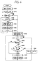
- FIG. 4 shows a control routine of the ECU 26 during the heating mode of the refrigerant cycle system.
- the control routine of FIG. 4 starts, when an ignition switch (not shown) of the vehicle engine 12 is turned on and the hot gas switch 41 of the air-conditioning operation panel 40 is turned on, for example.
- step S100 sensor signals from the sensors 30-35 and operation signals from the operation switches 41-45 of the air-conditioning operation panel 40 are input.
- step S110 flag G is set at 0, timer H is set at 0, and timer J is set at 0, so that an initialization is performed.
- step S130 it is determined whether or not outside air temperature Tam is equal to or lower than -20°C.
- the timer J passes a predetermined time (e.g., 30 seconds).
- the timer J is set at 0 immediately after the control routine starts. In this case, the first electromagnetic valve 13 is opened and the second electromagnetic valve 21 is closed, so that the cooling mode is set. That is, until the timer J passes through the predetermined time (e.g., 30sec), the cooling mode is set firstly.
- the electromagnetic clutch 11 is turned on, and the compressor 10 is operated.
- the cooling mode is provisionally set for recovering refrigerant staying in the condenser 14 during a stop of the refrigerant cycle system into the hot-gas bypass circuit.
- the outside air temperature Tam is equal to or lower than -20°C
- refrigerant saturation pressure relative to the outside air temperature Tam is greatly decreased. In this state, a pressure difference between the refrigerant pressure of the condenser 14 and the suction refrigerant pressure of the compressor 10 becomes little, and it is difficult to recover refrigerant staying in the condenser 14.
- the cooling mode is provisionally set at a start time of the refrigerant cycle system, so that refrigerant staying in the condenser 14 can be forcibly recovered when the outside air temperature Tam is equal to or lower than -20°C.
- the refrigerant recovering operation is performed until the timer J passes the predetermined time (e.g., 30 seconds).
- the predetermined time passes at step S140, the first electromagnetic valve 13 is closed and the second electromagnetic valve 21 is opened at step S180, and the heating mode of the refrigerant cycle system is set.
- the timer H passes the predetermined time (e.g., H ⁇ 30 sec)
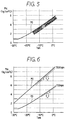
- the refrigerant shortage area S is determined based on the relationship between the outside air temperature Tam and the high-pressure side refrigerant pressure Phi, shown in FIG. 5.
- the line PO indicates a boundary line between a refrigerant shortage area S and a normal area.
- the map of FIG. 5 is beforehand stored in ROM of the micro-computer of the ECU 26.
- the compressor 10 and the high-pressure pipe portions of the refrigerant cycle system are generally disposed in the engine compartment of the vehicle, and are exposed by the outside air. Therefore, even when the refrigerant amount is in a normal area, the boundary line PO is decreased in accordance with a decrease of outside air temperature.
- step S230 When it is determined that the high-pressure side refrigerant pressure Phi is in the normal state (i.e., Phi > PO) at step S230, the turn-on state of the electromagnetic clutch 11 is continuously maintained and the compressor 10 is continuously operated. On the other hand, when it is determined that the high-pressure side refrigerant pressure Phi is in the refrigerant shortage area S (i.e., Phi ⁇ PO) at step S230, the electromagnetic clutch 11 is turned off and the operation of the compressor 10 is stopped at step S240. Further, at step S240, the flag G is set at 1. Thereafter, in this case, the control program is directly moved from step S190 to step S240, and the stop state of the compressor 10 is maintained.
- the control program is directly moved from step S190 to step S240, and the stop state of the compressor 10 is maintained.
- the operation of the compressor 10 is stopped. Therefore, it can prevent the compressor 10 from operating with a lubrication oil shortage, and the compressor 10 is accurately protected.
- the refrigerant shortage is determined based on the high-pressure side refrigerant pressure Phi at step S230. Therefore, the refrigerant shortage of the refrigerant cycle system is accurately determined.
- a pressure difference between the high-pressure side refrigerant pressures (or between the low-pressure side refrigerant pressures) during the normal refrigerant state and during the refrigerant shortage state is small.
- the predetermined time e.g., 30 sec
- the refrigerant shortage is determined based on the high-pressure side refrigerant pressure Phi, and the refrigerant shortage is accurately determined.
- a second preferred embodiment of the present invention will be now described with reference to FIG. 6.
- the high-pressure side refrigerant pressure Phi is decreased in accordance with a decrease of the rotation speed of the compressor 10. Therefore, in the second embodiment, the boundary line PO of the high-pressure side refrigerant pressure Phi between during the normal refrigerant state and during the refrigerant shortage state is corrected to be decreased as a decrease of the rotation speed of the compressor 10.
- the boundary line PO is corrected to be decreased.
- the boundary line PO of the high-pressure side refrigerant pressure Phi between during the normal refrigerant state and during the refrigerant shortage state may be corrected to be decreased as an air amount blown into the evaporator 18 is increased.
- FIG. 7 is a Mollier diagram of refrigerant R134a of a refrigerant cycle system according to the third embodiment.
- the super-heating degree of refrigerant is increased as compared with that during normal state.
- a refrigerant temperature sensor 36 for detecting the super-heating degree of high-pressure side refrigerant is further disposed at a refrigerant discharge side of the compressor 10, and the super-heating degree SH of the high-pressure side refrigerant is calculated based on the refrigerant temperature detected by the refrigerant temperature sensor 36 and the refrigerant pressure detected by the refrigerant pressure sensor 35.
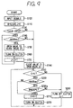
- FIG. 9 shows a control routine of the ECU 26 of a refrigerant cycle system according to the third embodiment.
- step S230a corresponding to step S230 in FIG. 4
- a predetermined degree e.g. 20°C.
- the super-heating degree SH of the high-pressure side refrigerant is larger than the predetermined degree, the refrigerant shortage is determined, and the electromagnetic clutch 11 is turned off so that the operation of the compressor 10 is stopped at step S240.
- the other steps are similar to those in FIG. 4.
- the super-heating degree SH of the high-pressure side refrigerant is calculated based on the refrigerant temperature detected by the refrigerant temperature sensor 36 and the refrigerant pressure detected by the refrigerant pressure sensor 35.
- the super-heating degree SH of the low-pressure side refrigerant is also increased as compared with during the normal state.
- the super-heating degree SH of the low-pressure side refrigerant at a position such as the refrigerant inlet and outlet of the evaporator 18, the bottom side of the accumulator 19 and the refrigerant suction side of the compressor 10 may be detected, and the refrigerant shortage may be determined based on the super-heating degree SH of the low-pressure side refrigerant.
- line Ls indicates a saturation line of refrigerant R134a.
- the liquid refrigerant becomes smaller in the refrigerant cycle system, and refrigerant pressure before the starting operation of the refrigerant cycle system is not increased to the saturation refrigerant pressure relative to outside air temperature Tam as shown by the slanting line portion A.
- the slanting line portion A is an area in which the saturation refrigerant pressure relative to outside air temperature Tam is higher than the atmosphere pressure Pat (outside air pressure).
- the slanting line portion B is an area in which the saturation refrigerant pressure relative to outside air temperature Tam is lower than the atmosphere pressure Pat.
- the saturation refrigerant pressure relative to outside air temperature Tam is lower than the atmosphere pressure Pat, outside air flows into the refrigerant cycle system from refrigerant leakage points. Therefore, the refrigerant pressure of the refrigerant cycle system is not set lower than the atmosphere pressure Pat.
- the slanting line portion A is an abnormal area when the saturation refrigerant pressure relative to outside air temperature Tam is higher than the atmosphere pressure Pat.
- the slanting line portion B is an abnormal area when the saturation pressure relative to outside air temperature Tam is lower than the atmosphere pressure Pat.
- the refrigerant shortage may be determined based on the refrigerant pressure before the start operation of the refrigerant cycle system.
- the other portions are similar to those in the first embodiment.
- the boundary line PO between a refrigerant shortage area S and the normal area described in the first embodiment can be set larger than the saturation refrigerant line Ls by a predetermined pressure at an outside air temperature, as shown in FIG. 11.
- the predetermined pressure between the boundary line PO and the saturation refrigerant line Ls is changed in accordance with the outside air temperature Tam.
- the refrigerant shortage can be determined, when the refrigerant pressure during a stop of the heating mode is lower than a pre-set value (e.g., PO) which is larger than the saturation refrigerant pressure relative to the outside air temperature Tam by a predetermined pressure.
- a pre-set value e.g., PO
- the receiver 15 and the thermal expansion valve 16 are disposed in the refrigerant cycle of the cooling mode.
- the receiver 15 may be not provided, and a fixed throttle may be used instead of the thermal expansion valve 16.
- a single switching unit may be used instead of both the first and second electromagnetic valves 13, 20, a single switching unit may be used.
- the hot gas switch 41 for setting the heating mode is provided in the air-conditioning operation panel 40.
- the heating mode may be set by the other switch without using the hot gas switch 41.
- the heating mode due to the hot-gas bypass may be started with a turn-on operation of the manual operation switch.
- the heating mode due to the hot-gas bypass is automatically started based on a heating signal from the engine electronic control unit.
Landscapes
- Engineering & Computer Science (AREA)
- Physics & Mathematics (AREA)
- Mechanical Engineering (AREA)
- Thermal Sciences (AREA)
- General Engineering & Computer Science (AREA)
- Air-Conditioning For Vehicles (AREA)
- Compression-Type Refrigeration Machines With Reversible Cycles (AREA)
Applications Claiming Priority (2)
| Application Number | Priority Date | Filing Date | Title |
|---|---|---|---|
| JP18338299 | 1999-06-29 | ||
| JP11183382A JP2001012830A (ja) | 1999-06-29 | 1999-06-29 | 冷凍サイクル装置 |
Publications (3)
| Publication Number | Publication Date |
|---|---|
| EP1065452A2 true EP1065452A2 (de) | 2001-01-03 |
| EP1065452A3 EP1065452A3 (de) | 2002-01-30 |
| EP1065452B1 EP1065452B1 (de) | 2005-01-19 |
Family
ID=16134802
Family Applications (1)
| Application Number | Title | Priority Date | Filing Date |
|---|---|---|---|
| EP00111988A Expired - Lifetime EP1065452B1 (de) | 1999-06-29 | 2000-06-19 | Kältekreislauf mit Heissgasnebenleitungsanordnung |
Country Status (4)
| Country | Link |
|---|---|
| US (1) | US6266965B1 (de) |
| EP (1) | EP1065452B1 (de) |
| JP (1) | JP2001012830A (de) |
| DE (1) | DE60017506T8 (de) |
Cited By (2)
| Publication number | Priority date | Publication date | Assignee | Title |
|---|---|---|---|---|
| EP1942307A3 (de) * | 2007-01-05 | 2013-12-04 | Hitachi Appliances, Inc. | Klimaanlage und Verfahren zum Bestimmen der Kühlmittelmenge |
| CN108583201A (zh) * | 2018-04-05 | 2018-09-28 | 宁波依诺汽车电子有限公司 | 汽车空调压力传感器 |
Families Citing this family (20)
| Publication number | Priority date | Publication date | Assignee | Title |
|---|---|---|---|---|
| JP4085694B2 (ja) * | 2002-02-27 | 2008-05-14 | 株式会社デンソー | 空気調和装置 |
| JP3931739B2 (ja) | 2002-06-12 | 2007-06-20 | 株式会社デンソー | 冷凍サイクル装置 |
| JP4467899B2 (ja) * | 2003-02-24 | 2010-05-26 | 株式会社デンソー | 冷凍サイクル装置 |
| JP2004338447A (ja) * | 2003-05-13 | 2004-12-02 | Denso Corp | 空調装置 |
| US6901957B2 (en) * | 2003-07-28 | 2005-06-07 | Carrier Corporation | Hot gas bypass isolation |
| JP4705878B2 (ja) * | 2006-04-27 | 2011-06-22 | ダイキン工業株式会社 | 空気調和装置 |
| JP5125116B2 (ja) * | 2007-01-26 | 2013-01-23 | ダイキン工業株式会社 | 冷凍装置 |
| JP4990702B2 (ja) * | 2007-07-19 | 2012-08-01 | シャープ株式会社 | 冷媒漏洩検出装置、空気調和機及び冷媒漏洩検出方法 |
| US20120011867A1 (en) * | 2009-04-03 | 2012-01-19 | Carrier Corporation | Multi-circuit heat exchanger |
| JP2011140291A (ja) * | 2010-01-11 | 2011-07-21 | Denso Corp | 車両用空調装置 |
| JP5418280B2 (ja) * | 2010-02-17 | 2014-02-19 | 株式会社デンソー | 蒸発器 |
| JP5625841B2 (ja) * | 2010-12-07 | 2014-11-19 | 株式会社デンソー | 燃料供給システム |
| DE102011006970A1 (de) * | 2011-03-23 | 2012-09-27 | Robert Bosch Gmbh | Verfahren sowie Diagnosetester zum Erkennen eines Fehlers in einem Kühlkreislauf eines Kraftfahrzeugs |
| JP5989328B2 (ja) * | 2011-11-17 | 2016-09-07 | トヨタ自動車株式会社 | 熱交換装置 |
| CN102582393A (zh) * | 2012-03-07 | 2012-07-18 | 浙江吉利汽车研究院有限公司 | 电动汽车驱动电机温度控制系统 |
| JP2014009869A (ja) * | 2012-06-28 | 2014-01-20 | Denso Corp | ヒートポンプサイクル |
| JP6095155B2 (ja) * | 2012-12-27 | 2017-03-15 | 中野冷機株式会社 | 冷凍装置及び冷凍装置の冷媒漏れ検知方法 |
| JP6746742B1 (ja) * | 2019-03-15 | 2020-08-26 | 三菱重工サーマルシステムズ株式会社 | 車両用空調システムおよび車両用空調システムの制御方法 |
| JP2023075844A (ja) * | 2021-11-19 | 2023-05-31 | サンデン株式会社 | 車両用空調装置 |
| JP7783063B2 (ja) * | 2022-01-24 | 2025-12-09 | サンデン株式会社 | 車両用空調装置 |
Citations (1)
| Publication number | Priority date | Publication date | Assignee | Title |
|---|---|---|---|---|
| JPH05272817A (ja) | 1992-01-30 | 1993-10-22 | Nippondenso Co Ltd | 空調装置 |
Family Cites Families (9)
| Publication number | Priority date | Publication date | Assignee | Title |
|---|---|---|---|---|
| US4220010A (en) * | 1978-12-07 | 1980-09-02 | Honeywell Inc. | Loss of refrigerant and/or high discharge temperature protection for heat pumps |
| JPS63162272U (de) * | 1987-04-13 | 1988-10-24 | ||
| JP3237187B2 (ja) * | 1991-06-24 | 2001-12-10 | 株式会社デンソー | 空調装置 |
| US5457965A (en) * | 1994-04-11 | 1995-10-17 | Ford Motor Company | Low refrigerant charge detection system |
| US5481884A (en) * | 1994-08-29 | 1996-01-09 | General Motors Corporation | Apparatus and method for providing low refrigerant charge detection |
| US5586445A (en) * | 1994-09-30 | 1996-12-24 | General Electric Company | Low refrigerant charge detection using a combined pressure/temperature sensor |
| FR2756913B1 (fr) * | 1996-12-09 | 1999-02-12 | Valeo Climatisation | Circuit de fluide refrigerant comprenant une boucle de climatisation et une boucle de rechauffage, en particulier pour vehicule automobile |
| US6205798B1 (en) * | 1999-01-19 | 2001-03-27 | Carrier Corporation | Test for the automated detection of leaks between high and low pressure sides of a refrigeration system |
| US6098412A (en) * | 1999-01-19 | 2000-08-08 | Carrier Corporation | Method for automated detection of leaks in a discharge check valve |
-
1999
- 1999-06-29 JP JP11183382A patent/JP2001012830A/ja active Pending
-
2000
- 2000-06-12 US US09/591,735 patent/US6266965B1/en not_active Expired - Lifetime
- 2000-06-19 EP EP00111988A patent/EP1065452B1/de not_active Expired - Lifetime
- 2000-06-19 DE DE60017506T patent/DE60017506T8/de active Active
Patent Citations (1)
| Publication number | Priority date | Publication date | Assignee | Title |
|---|---|---|---|---|
| JPH05272817A (ja) | 1992-01-30 | 1993-10-22 | Nippondenso Co Ltd | 空調装置 |
Cited By (2)
| Publication number | Priority date | Publication date | Assignee | Title |
|---|---|---|---|---|
| EP1942307A3 (de) * | 2007-01-05 | 2013-12-04 | Hitachi Appliances, Inc. | Klimaanlage und Verfahren zum Bestimmen der Kühlmittelmenge |
| CN108583201A (zh) * | 2018-04-05 | 2018-09-28 | 宁波依诺汽车电子有限公司 | 汽车空调压力传感器 |
Also Published As
| Publication number | Publication date |
|---|---|
| DE60017506T2 (de) | 2006-03-23 |
| EP1065452A3 (de) | 2002-01-30 |
| US6266965B1 (en) | 2001-07-31 |
| DE60017506T8 (de) | 2009-11-19 |
| DE60017506D1 (de) | 2005-02-24 |
| JP2001012830A (ja) | 2001-01-19 |
| EP1065452B1 (de) | 2005-01-19 |
Similar Documents
| Publication | Publication Date | Title |
|---|---|---|
| EP1065452B1 (de) | Kältekreislauf mit Heissgasnebenleitungsanordnung | |
| US6058728A (en) | Refrigerant cycle for vehicle air conditioner | |
| US7150158B2 (en) | Freezing prevention system for refrigeration device and air conditioner using the same | |
| US20070125106A1 (en) | Supercritical refrigeration cycle | |
| US6397613B1 (en) | Refrigerating cycle apparatus | |
| US6898944B2 (en) | Air conditioner | |
| EP1000787A3 (de) | Wärmepumpenartige Klimaanlage für ein Fahrzeug und Verfahren zur Korrosionsinhibierung und zum Erleichtern von Schnellerwärmung eines Fahrgastraumes während niedriger Temperaturen | |
| US6371202B1 (en) | Vehicle air conditioner | |
| JP3189255B2 (ja) | 空調装置 | |
| US6725676B2 (en) | Refrigerant cycle system with hot gas heating function | |
| JP2018202896A (ja) | 車両用空調装置 | |
| US6935125B2 (en) | Air conditioning system | |
| US6751968B2 (en) | Vehicle air conditioner having refrigerant cycle with heating function | |
| EP0818333A2 (de) | Wärmepumpe des Gaseinspritztyps | |
| JP4655893B2 (ja) | 車両用冷凍サイクル装置 | |
| JP2005043008A (ja) | 冷凍サイクル装置 | |
| EP1318037B1 (de) | Heissgasfahrzeugklimaanlage mit Heizungsbetriebsart | |
| JP2001050572A (ja) | 自動車用空気調和装置 | |
| GB2396689A (en) | Vehicle air conditioner having refrigerant cycle with hot gas bypass heating function | |
| JP2005337654A (ja) | 冷凍サイクル装置 | |
| JP2000071756A (ja) | ヒートポンプ式自動車用空気調和装置 | |
| JP2000111180A (ja) | 冷凍サイクル装置 | |
| JP2007327701A (ja) | 冷凍サイクル装置 | |
| JP2003035458A (ja) | 冷凍サイクル装置 | |
| JP2601004B2 (ja) | 車両用空調装置 |
Legal Events
| Date | Code | Title | Description |
|---|---|---|---|
| PUAI | Public reference made under article 153(3) epc to a published international application that has entered the european phase |
Free format text: ORIGINAL CODE: 0009012 |
|
| AK | Designated contracting states |
Kind code of ref document: A2 Designated state(s): AT BE CH CY DE DK ES FI FR GB GR IE IT LI LU MC NL PT SE Kind code of ref document: A2 Designated state(s): DE FR GB IT |
|
| AX | Request for extension of the european patent |
Free format text: AL;LT;LV;MK;RO;SI |
|
| RIN1 | Information on inventor provided before grant (corrected) |
Inventor name: TAKANO, YOSHIAKI, C/O DENSO CORPORATION Inventor name: IZAWA, SATOSHI, C/O DENSO CORPORATION Inventor name: ITO, HAJIME, C/O DENSO CORPORATION |
|
| PUAL | Search report despatched |
Free format text: ORIGINAL CODE: 0009013 |
|
| AK | Designated contracting states |
Kind code of ref document: A3 Designated state(s): AT BE CH CY DE DK ES FI FR GB GR IE IT LI LU MC NL PT SE |
|
| AX | Request for extension of the european patent |
Free format text: AL;LT;LV;MK;RO;SI |
|
| 17P | Request for examination filed |
Effective date: 20020311 |
|
| AKX | Designation fees paid |
Free format text: DE FR GB IT |
|
| 17Q | First examination report despatched |
Effective date: 20031113 |
|
| GRAP | Despatch of communication of intention to grant a patent |
Free format text: ORIGINAL CODE: EPIDOSNIGR1 |
|
| GRAS | Grant fee paid |
Free format text: ORIGINAL CODE: EPIDOSNIGR3 |
|
| GRAA | (expected) grant |
Free format text: ORIGINAL CODE: 0009210 |
|
| AK | Designated contracting states |
Kind code of ref document: B1 Designated state(s): DE FR GB IT |
|
| REG | Reference to a national code |
Ref country code: GB Ref legal event code: FG4D |
|
| REG | Reference to a national code |
Ref country code: IE Ref legal event code: FG4D |
|
| REF | Corresponds to: |
Ref document number: 60017506 Country of ref document: DE Date of ref document: 20050224 Kind code of ref document: P |
|
| ET | Fr: translation filed | ||
| PLBE | No opposition filed within time limit |
Free format text: ORIGINAL CODE: 0009261 |
|
| STAA | Information on the status of an ep patent application or granted ep patent |
Free format text: STATUS: NO OPPOSITION FILED WITHIN TIME LIMIT |
|
| REG | Reference to a national code |
Ref country code: GB Ref legal event code: 746 Effective date: 20051205 |
|
| 26N | No opposition filed |
Effective date: 20051020 |
|
| PGFP | Annual fee paid to national office [announced via postgrant information from national office to epo] |
Ref country code: FR Payment date: 20110621 Year of fee payment: 12 |
|
| PGFP | Annual fee paid to national office [announced via postgrant information from national office to epo] |
Ref country code: GB Payment date: 20110615 Year of fee payment: 12 |
|
| PGFP | Annual fee paid to national office [announced via postgrant information from national office to epo] |
Ref country code: IT Payment date: 20110614 Year of fee payment: 12 |
|
| GBPC | Gb: european patent ceased through non-payment of renewal fee |
Effective date: 20120619 |
|
| PG25 | Lapsed in a contracting state [announced via postgrant information from national office to epo] |
Ref country code: IT Free format text: LAPSE BECAUSE OF NON-PAYMENT OF DUE FEES Effective date: 20120619 |
|
| REG | Reference to a national code |
Ref country code: FR Ref legal event code: ST Effective date: 20130228 |
|
| PG25 | Lapsed in a contracting state [announced via postgrant information from national office to epo] |
Ref country code: GB Free format text: LAPSE BECAUSE OF NON-PAYMENT OF DUE FEES Effective date: 20120619 Ref country code: FR Free format text: LAPSE BECAUSE OF NON-PAYMENT OF DUE FEES Effective date: 20120702 |
|
| PGFP | Annual fee paid to national office [announced via postgrant information from national office to epo] |
Ref country code: DE Payment date: 20130612 Year of fee payment: 14 |
|
| REG | Reference to a national code |
Ref country code: DE Ref legal event code: R119 Ref document number: 60017506 Country of ref document: DE |
|
| REG | Reference to a national code |
Ref country code: DE Ref legal event code: R119 Ref document number: 60017506 Country of ref document: DE Effective date: 20150101 |
|
| PG25 | Lapsed in a contracting state [announced via postgrant information from national office to epo] |
Ref country code: DE Free format text: LAPSE BECAUSE OF NON-PAYMENT OF DUE FEES Effective date: 20150101 |