EP1065882B1 - Dispositif et méthode de codage hierarchique avec mémoire pour un signal numérique d'image - Google Patents
Dispositif et méthode de codage hierarchique avec mémoire pour un signal numérique d'image Download PDFInfo
- Publication number
- EP1065882B1 EP1065882B1 EP00111790A EP00111790A EP1065882B1 EP 1065882 B1 EP1065882 B1 EP 1065882B1 EP 00111790 A EP00111790 A EP 00111790A EP 00111790 A EP00111790 A EP 00111790A EP 1065882 B1 EP1065882 B1 EP 1065882B1
- Authority
- EP
- European Patent Office
- Prior art keywords
- data
- memory
- hierarchical level
- signal processing
- memory means
- Prior art date
- Legal status (The legal status is an assumption and is not a legal conclusion. Google has not performed a legal analysis and makes no representation as to the accuracy of the status listed.)
- Expired - Lifetime
Links
Images


Classifications
-
- G—PHYSICS
- G11—INFORMATION STORAGE
- G11C—STATIC STORES
- G11C7/00—Arrangements for writing information into, or reading information out from, a digital store
-
- H—ELECTRICITY
- H04—ELECTRIC COMMUNICATION TECHNIQUE
- H04N—PICTORIAL COMMUNICATION, e.g. TELEVISION
- H04N19/00—Methods or arrangements for coding, decoding, compressing or decompressing digital video signals
- H04N19/60—Methods or arrangements for coding, decoding, compressing or decompressing digital video signals using transform coding
- H04N19/63—Methods or arrangements for coding, decoding, compressing or decompressing digital video signals using transform coding using sub-band based transform, e.g. wavelets
-
- H—ELECTRICITY
- H04—ELECTRIC COMMUNICATION TECHNIQUE
- H04N—PICTORIAL COMMUNICATION, e.g. TELEVISION
- H04N19/00—Methods or arrangements for coding, decoding, compressing or decompressing digital video signals
- H04N19/42—Methods or arrangements for coding, decoding, compressing or decompressing digital video signals characterised by implementation details or hardware specially adapted for video compression or decompression, e.g. dedicated software implementation
Definitions
- the present invention relates to memory and to reading/writing data to/from same.
- a hierarchical encoding process for generating picture signals in a plurality of hierarchical levels that differ in resolutions is known.
- a picture in a first hierarchical level, a picture in a second hierarchical level, a picture in a third hierarchical level, and so forth are formed in such a manner that the data in the first hierarchical level is a high resolution picture signal, the resolution of the data in the second hierarchical level is lower than the resolution of the data in the first hierarchical level, and the resolution of the data in the third hierarchical level is lower than the resolution of the data in the second hierarchical level.
- a plurality of picture signals are transmitted through one transmission path (a communication path or a record medium). With picture monitors corresponding to the hierarchical levels on the receiving side, picture data can be reproduced.
- the hierarchical encoding process can be applied to enlargement and reduction of pictures (namely, electronic zooming).
- the enlargement and reduction of pictures have been widely used for video game applications and so forth.
- the picture signal in the first hierarchical level is thinned out to 1/4 thereof so as to form the picture signal in the second hierarchical level.
- the picture signal in the second hierarchical level is interpolated so as to form an interpolation signal in the first hierarchical level.
- the difference between the interpolation signal in the first hierarchical level and the input picture signal is calculated so as to form a difference signal.
- the difference signal is transmitted.
- the number of pixels of the difference signal is the same as the number of pixels of the input picture signal.
- the signal in the second hierarchical level is transmitted.
- the amount of data to be transmitted is larger than the amount of original data.
- EP-A-0 438 195 discloses a signal processing apparatus according to the pre-characterising part of claim 1 hereof.
- EP-A-0 627 859 discloses a hierarchical picture signal encoding technique in which averaged values of one hierarchical level are subsumed into another level.
- the present invention provides a signal processing apparatus according to claim 1 hereof and a method of generating data values according to claim 10 hereof.
- the signal processing means may perform a hierarchical encoding process for forming a pixel in a second hierarchical level that is an input digital picture signal.
- the memory means may store (N - 1) pixels in the first hierarchical level and one pixel in the second hierarchical level.
- the signal processing means may be arranged to perform a hierarchical decoding process, corresponding to a hierarchical encoding process, for generating at least data in a first hierarchical level and data in a second hierarchical level with the input picture data, the data in the first hierarchical level being different from the data in the second hierarchical level in resolutions and restoring data in the first hierarchical level that has not been written to the memory means with the data in the first hierarchical level and the data in the second hierarchical level being read from the memory means.
- the hierarchical encoding process is accomplished by an average value calculating means for forming the data in the second hierarchical level with the average value of every N pixels of the data in the first hierarchical level and a means for outputting (N - 1) pixels of the data in the first hierarchical level and one pixel of the data in the second hierarchical level to the memory means.
- the hierarchical encoding process is accomplished by an average value calculating means for forming the data in the second hierarchical level with the average value of every N pixels of the data in the first hierarchical level, a difference data generating means for generating (N - 1) difference values between the average value of the data in the second hierarchical level and the data in the first hierarchical level, and a means for outputting the (N - 1) difference values in the first hierarchical level received from the difference data generating means and the data in the second hierarchial level received from the average value calculating means to the memory means.
- the memory apparatus for a digital picture signal has a controlling means for controlling the arithmetic operation means and the memory means in such a manner that the controlling means reads data from the memory means, performs an arithmetic operation for the data, and writes the resultant data to the memory means so as to form the data in the first hierarchical level.
- data in the higher hierarchial level is formed of an average value of a plurality of pixels in a predetermined hierarchical level.
- a part of pixels in the higher hierarchical level instead of pixels in the predetermined hierarchical level is written to the memory.
- Data in each hierarchical level can be obtained from a read output of the memory.
- the signal processing circuit and the semiconductor memory can be structured as a one chip IC circuit.
- the signal processing circuit since data necessary for forming average value data is read from the memory, the signal processing circuit does not need to have a pixel delaying circuit and a line delaying circuit. Thus, the scale of the hardware can be reduced.
- a preferred form of implementation of the invention described hereinbelow provides a memory apparatus for a digital picture signal, the memory apparatus having a real time signal processing circuit, in particular a hierarchical encoding circuit disposed in an IC circuit, a writing method therefor, and a reading method thereof.
- the preferred memory apparatus can store hierarchically structured picture data in an amount which is the same as the amount of original input picture data, and can reduce the cost and space requirement of an IC circuit.
- both a signal processing circuit that preforms a signal process on the real time basis and a semiconductor memory are structured on a common semiconductor substrate as one chip IC circuit.
- a signal processing circuit that performs a hierarchical encoding process and a hierarchical decoding process for a picture signal and a semiconductor memory (RAM) are structured as one chip IC circuit.
- a signal processing circuit that performs a hierarchical encoding process and a semiconductor memory 1 are structured as one chip IC.
- Picture data that has been sampled at a predetermined sampling frequency (for example, 13.5 MHz) and where one sample has been quantized with a predetermined number of bits (for example, eight bits) is supplied from an input terminal 2.
- a clock signal that synchronizes with the input picture data is supplied from an input terminal 3.
- the input picture data is supplied in the TV raster scanning sequence.
- the first embodiment of the present invention has a minimum number of hierarchical levels that are a first hierarchical level and a second hierarchial level.
- Data in the first hierarchical structure is input picture data.
- the resolution of the data in the second hierarchical level is lower than the resolution of the data in the first hierarchical level.
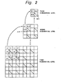
- the hierarchical encoding process will be described in a structure having a first hierarchical level, a second hierarchical level, and a third hierarchical level.
- a partial picture (8 x 8 pixels) in the first hierarchical level is shown as the lowest position.
- each square represents one pixel.
- An average value of every four pixels (2 x 2 pixels) in the first hierarchical level is calculated.
- ml 1/4 ⁇ (a + b + e + f)
- an average value of (2 x 2) pixels that are spatially adjacent in the second hierarchical level is calculated.
- a pixel in the higher hierarchical level is transmitted.
- a pixel m1 in the second hierarchical level is transmitted.
- a pixel M1 in the third hierarchical level is transmitted.
- the pixel m4 in the second hierarchical level can be decoded.
- the pixel p in the first hierarchical level can be decoded. It should be noted that the position of a pixel that is omitted is not limited to the lower right corner position.
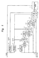
- the clock signal that synchronizes with the input data and that is input from the input terminal 3 is supplied to frequency dividing circuits 4 and 5.
- the frequency dividing circuits 4 and 5 each divide the frequency of the clock signal by 2. Assuming that the sampling frequency is denoted by Fs, the frequency dividing circuit 4 generates a clock signal with a frequency of 1/2 ⁇ Fs. Likewise, assuming that the horizontal scanning frequency is denoted by Fh, the frequency dividing circuit 5 generates a clock signal with a frequency of 1/2 ⁇ Fh.
- the input picture data is supplied to a one-pixel delaying circuit 6, an adding device 7, an adding device 10, an adding device 13, and a selecting circuit 15.
- the output data of the one-pixel delaying circuit 6 is supplied to the adding device 7.
- the output data of the adding device 7 is supplied to a one-line delaying circuit 9 through a selecting circuit 8.
- the adding device 10 adds the input data and the output data of the line delaying circuit 9.
- the output data of the adding device 10 is supplied to one-pixel delaying circuit 12 through a selecting circuit 11.
- the adding device 13 adds the input data and the output data of the one-pixel delaying circuit 12.
- the output data of the adding device 13 is supplied to a selecting circuit 15 through a dividing circuit 14 that performs a divide-by-4 operation.
- the selecting circuit 15 selects the input data or the output data of the dividing circuit 14.
- the output data of the selecting circuit 15 is supplied as write data to the semiconductor memory 1.
- the clock signal is supplied from the input terminal 3 to the semiconductor memory 1.
- a write address and a read address (not shown) are generated using the clock signal.
- a control signal for controlling the writing operation and the reading operation is generated using the clock signal.
- the 1/2 - Fs clock signal is supplied from the frequency dividing circuit 4 to the selecting circuits 8 and 11.
- the selecting circuits 8 and 11 select and output the output data of the adding devices 7 and 10 at intervals of every two pixels corresponding to the frequency divided clock signal, respectively.
- the output data of the selecting circuits 8 and 11 varies at intervals of every two pixels.
- the clock signal with the frequency of 1/2 ⁇ Fs and the clock signal with the frequency of 1/2 ⁇ Fh are supplied from the frequency dividing circuits 4 and 5 to the selecting circuit 15.
- the selecting circuit 15 alternately selects the input data or the output data of the dividing circuit 14 at intervals of every line.
- the output data of the selecting circuit 14 is selected at intervals of every two pixels.
- the output data of the selecting circuit 15 on the selected line varies at intervals of every two pixels.
- each circuit shown in Fig. 1 when a pixel f is supplied to the input terminal 2, each circuit shown in Fig. 1 generates output data.
- the output data of the one-pixel delaying circuit 6 is a pixel e.
- the output data of the adding device 7 is pixels (e + f).
- the selecting circuit 8 selects the output data of the adding device 7 at intervals of every two pixels.
- the pixels (e + f) are selected data.
- added pixels (f + g) are not selected data. Consequently, the one-line delaying circuit 9 generates added pixels (a + b) that are pixels one line before. Consequently, the adding device 10 generates added pixels (a + b + f).
- the selecting circuit 11 that receives the output data of the adding device 10 selects the output data of the adding device 10 at intervals of every two pixels and supplies the selected output data to the one-pixel delaying circuit 12 at the same timing (in the same phase) as the selecting circuit 8.
- the one-pixel delaying circuit 12 generates pixels (a + b + c).
- the adding device 13 adds the pixels (a + b + e) and the input pixel f and generates added pixels (a + b + e + f).
- the selecting circuit 15 selects the average value data as the pixel m1 instead of the input pixel f and supplies the pixel m1 to the semiconductor memory 1. In the semiconductor memory 1, the average value as the pixel m1 is written to an address for the pixel f.
- Fig. 4 shows an example of the structure of a reading side of the semiconductor memory 1.
- a sampling clock that synchronizes with read data of the semiconductor memory 1 is supplied from an input terminal 3.
- Frequency dividing circuits 4 and 5 form a clock signal with a frequency of 1/2 .
- Data read from the semiconductor memory 1 is supplied to a one-pixel delaying circuit 16, an adding device 17, an adding device 20, a multiply-by-4 circuit, and a selecting circuit 25.
- the structure of the reading side is similar to the structure of the writing side shown in Fig. 1.
- the one-pixel delaying circuit 16, the adding device 17, the selecting circuit 18, the adding device 20, the selecting circuit 21, the one-pixel delaying circuit 22, and the selecting circuit 25 shown in Fig. 4 correspond to the one-pixel delaying circuit 6, the adding device 7, the selecting circuit 8, the adding device 10, the selecting circuit 11, the one-pixel delaying circuit 12, and the selecting circuit 15, respectively.
- the adding device 13 is disposed on the writing side
- a subtracting device 23 is disposed on the reading side as shown in Fig. 4.
- the adding device 13 and the dividing circuit 14 are disposed on the writing side
- a subtracting device 23 and the multiply-by-4 circuit 24 are disposed on the reading side.
- each circuit shown in Fig. 4 when the pixel m1 in the second hierarchical level instead of the pixel f is read from the semiconductor memory 1, each circuit shown in Fig. 4 generates output data.
- the operation of the reading side is similar to the operation of the writing side shown in Fig. 1.
- the multiplying circuit 24 generates data (4 x m1).
- the subtracting device 23 performs a subtracting operation ⁇ 4 x m1 - (a + b + e) ⁇ .
- the subtracting device 23 generates the pixel f.
- the pixel f is selected by the selecting circuit 25 and then obtained from an output terminal 26.
- the output terminal 26 generates a pixel in the first hierarchical level.
- a selecting circuit that selects only data in the second hierarchical level from the read output of the semiconductor memory 1 is disposed.
- data in the first hierarchical level and data in the second hierarchical level can be read in parallel.
- the structure on the writing side shown in Fig. 1 is almost similar to the structure on the reading side shown in Fig. 4.
- the hardware structure of the adding device 13 is the same as the hardware structure of the subtracting device 23.
- the hardware structure of the dividing circuit 14 is the same as the hardware structure of the multiplying circuit 24 except for the direction of two-bit shifting operation.
- the writing side and the reading side can be accomplished as common hardware. Consequently, the scale of hardware that performs the hierarchical encoding process and the hierarchical decoding process can be reduced.
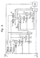
- Fig. 5 is a block diagram showing a second embodiment of the present invention.
- Fig. 5 shows a structure of a signal process for writing encoded data in three hierarchical levels to a semiconductor memory 1.
- the structure for forming data in the second hierarchical level with data in the first hierarchical level is the same as the structure shown in Fig. 1.
- similar portions to those shown in Fig. 1 are denoted by similar reference numerals with suffix a and their description is omitted.
- the selecting circuit 15a outputs data in the second hierarchical level (namely, pixels m1, m2, m3, m4, and so forth).
- a frequency dividing circuit 4b is connected to a frequency dividing circuit 4a.
- a frequency dividing circuit 5b is connected to a frequency dividing circuit 5a.
- the frequency dividing circuit 4b generates a clock signal with a frequency of 1/4 ⁇ Fs.
- the frequency dividing circuit 5b generates a clock signal with a frequency of 1/4 ⁇ Fh.
- the clock signal with the frequency of 1/4 ⁇ Fs and the clock signal with the frequency of 1/4 ⁇ Fh are supplied to selecting circuits 8b and 15b, respectively.
- Input picture data (data in the first hierarchical level) and data in the second hierarchical level received from a selecting circuit 15a are supplied to a selecting circuit 15b.
- the output data of the selecting circuit 15b is written to the semiconductor memory 1.
- data in the second hierarchical level is supplied to a two-pixel delaying circuit 6b, an adding device 7b, an adding device 10b, and an adding device 13b.
- the two-pixel delaying circuit 6b, the adding device 7b, a selecting circuit 8b, a two-line delaying circuit 9b, the adding device 10b, a selecting circuit 11b, a two-pixel delaying circuit 12b, the adding device 13b, a dividing circuit 14b, and a selecting circuit 15b are disposed.
- the selecting circuit 15b selects the pixel M1 instead of the pixel p and supplies the selected pixel M1 to the semiconductor memory 1.
- the selecting circuit 15b selects data in the second hierarchical level received from the selecting circuit 15a or the input data corresponding to the predetermined timings.
- pixels m1, m2, m3, and so forth in the second hierarchical level instead of pixels in the first hierarchical level are written to individual regions of (2 x 2 pixels).
- Pixels M1, M2, and so forth in the third hierarchical level instead of pixels in the second hierarchical level are written to individual regions of (4 x 4 pixels).
- the structure for reading data from the semiconductor memory 1 can be composed similar to the structure on the writing side.
- Fig. 7 shows a structure of a one-chip IC having a signal processing circuit that performs a hierarchical encoding process and a semiconductor chip 1.
- Fig. 7 similar portions to those in Fig. 1 are denoted by similar reference numerals and their description is omitted.
- the semiconductor memory 1 is composed of memories 1a and 1b.
- the memories 1a and 1b are composed of different memories or by dividing the memory space of one memory into two portions.
- the memory 1a stores data in the first and third hierarchical levels.
- the memory 1b stores data in the second hierarchical level.
- the memories 1a and 1b each have data input/output terminals, an address input terminal, and R/W signal input terminals (for controlling the reading/writing operations).
- Input picture data is supplied to an arithmetic operation circuit 34 and an input terminal 35a of a switch circuit 35.
- the output data of the arithmetic operation circuit 34 is supplied to an input terminal 35b of the switch circuit 35.
- the output data selected by the switch circuit 35 is supplied to a data input terminal IN of the memory 1a.
- Data read from the memories 1a and 1b is supplied to the arithmetic operation circuit 34.
- the arithmetic operation circuit 34 performs an adding process and an average calculating process for calculating average value data.
- a dividing process necessary for the average calculating process is a divide-by-4 process, a divide-by-16 process, or the like. The dividing process can be performed by a bit shifting operation.
- a clock signal is supplied from an input terminal 3 to a controller 36, a R/W signal generating circuit 37, write address generating circuits 38a and 38b, and read address generating circuits 39a and 39b.
- a R/W signal is supplied from the R/W signal generating circuit 37 to a R/W input terminal of the memory 1 and address selectors 40a and 40b.
- a write address is selected by the address selectors 40a and 40b.
- read addresses are selected by the address selectors 40a and 40b.
- the read addresses are supplied to the memory 1.
- connection lines are omitted, the clock signal is also supplied to the address generating circuits 38a, 38b, 39a, and 39b.
- the controller 36 controls the write address generating circuits 38a and 38b and the read address generating circuits 39a and 39b and generate addresses necessary for the arithmetic operations.
- the controller 36 controls the arithmetic operation circuit 34 so as to control the arithmetic operations.
- the controller 36 controls the switch circuit 35 so as to select data to be written to the memories 1a and 1b.
- the memories 1a and 1b successively perform a reading operation, an arithmetic operation (adding operation), and a writing operation at every clock cycle.
- a read enable signal REN and a write enable signal WEN become high in intervals of the reading operation and the writing operation, respectively.
- control signals (R/W signals) corresponding to the write enable signal WEN and the read enable signal REN are formed.
- Figs. 9A to 9D the hierarchical encoding process for pixels disposed as shown in Fig. 2 will be described.
- the switch circuit 35 selects the input pixels and supplies them to the memory 1a.
- pixels a, b, c, d, e, g, and so forth other than pixels f, h, n, and so forth corresponding to positions of data in the second hierarchical level are successively written to the memory 1a.
- the writing operation for the pixels a, b, c, d, e, g, and so forth it is not necessary to read data from the memory 1a.
- the reading operation of the memory 1a in one cycle of the memory operation shown in Fig. 8 is not enabled.
- Figs. 9(A) to (D) each show a part of memory regions of the memories 1a and 1b.
- added output data of the arithmetic operation circuit 34 is written to the memory 1b.
- data of an address to which data (for example, a pixel m1) in the second hierarchical level is read from the memory 1b.
- the read data and divided data of which the input pixel data has been divided by 4 are added.
- the added output data is written to the same address of the memory 1b.
- data ⁇ 1/4 ⁇ (a + b + e) ⁇ has been stored at an address to which the pixel m1 is written.
- the data ⁇ 1/4 ⁇ (a + b + e) ⁇ is read and then supplied to the arithmetic operation circuit 34.
- the arithmetic operation circuit 34 adds the input pixel data 1/4 ⁇ f and the read data and generates data ⁇ 1/4 ⁇ (a + b + e + f) as the pixel ml.
- the pixel ml is written to the same address of the memory 1b.
- Fig. 93 shows the state of which the pixel m1 has been written to the memory 1b.
- pixels such as a, b, e, and so forth are written to the memory 12, these pixels may be divided by 4. However, to prevent the required capacity of the memory from increasing, before these pixels are written to the memory 1b, they should be divided by 4.
- the position of the switch circuit 35 is changed.
- data of which the pixel m1 in the second hierarchical level generated from the arithmetic operation circuit 34 has been divided by 4 is written to an address (the position of pixel data p) for a pixel M1 in the third hierarchical level.
- the required capacity of the memory does not increase.
- data ⁇ 1/4 ⁇ (ml + m2 + m3) ⁇ has been stored at an address (the position of pixel p) for data in the third hierarchical level.
- this data is read and supplied to the arithmetic operation circuit 34.
- the arithmetic operation circuit 34 adds the read data and divided data of which the pixel m4 has been divided by 4 and generates data ⁇ 1/4 ⁇ (ml + m2 + m3 ⁇ m4) ⁇ as a pixel M1.
- the position of the switch circuit 35 is changed. As shown in Fig.
- the pixel M1 in the third hierarchical level generated from the arithmetic operation circuit 34 is written to the same address of the memory 1a.
- the pixel M1 (or m4) is written to an address for the pixel m4.
- Fig. 9D shows the state of which the pixel M1 has been written to the memories 1a and 1b.
- the structure of a reading side (not shown) of the third embodiment may be similar to the structure of the writing side shown in Fig. 7.
- the writing side and the reading side can be accomplished as common hardware. Consequently, the scale of the hardware for performing the hierarchical encoding process and the hierarchical decoding process can be reduced.
- Fig. 10 is a block diagram showing a structure of a fourth embodiment of the present invention.
- similar portions to those in Fig. 7 are denoted by similar reference numerals and their description is partly omitted.
- a semiconductor memory 1 is divided into three memories 1a, 1b, and 1c to which encoded data in three hierarchical levels is written.
- R/W signal generating circuits 37a, 37b, and 37c and address generating circuits 41a, 41b, and 41c are disposed.
- a control signal is supplied from a controller 36 to the R/W signal generating circuits 37a, 37b, and 37c and the address generating circuits 41a, 41b, and 41c.
- the contents of the memories 1a, 1b, and 1c have been initially cleared.
- Input data is supplied from an input terminal 2 to the memory 1a through an input register 2a.
- Data in the first hierarchical level (namely, input picture data) is written to the memory 1a as it is.
- input pixels f, h, p, and so forth for addresses corresponding to data in the second and third hierarchical levels are not written to the memory 1a.
- the required capacity of the memory 1a is 3/4 the required capacity in the case that the memory 1a stores all input picture data.
- the output data of an adding device 34c is supplied as input data to the memory 1b.
- the input picture data received from the register 2a is supplied to one input terminal of the adding device 34a through a divide-by-4 circuit 34a.
- Data read from the memory 1b is supplied to the other input terminal of the adding device 34c through a register 34b.
- the memory 1b has addresses corresponding to positions of data in the second hierarchical level (namely, pixels f, h, n, and so forth). Pixels m1, m2, m3, and so forth in the second hierarchical level are written to these addresses.
- the required capacity of the memory 1b is 3/16 the required capacity in the case that the memory 1b stores all input pixels.
- the output data of the dividing circuit 34a and the output data of the adding device 34c are supplied to a selector 34d.
- the output data of the selector 34d is supplied to one input terminal of an adding device 34f through a divide-by-4 circuit 34e.
- Data read from the memory 1c is supplied to the other input terminal of the adding device 34f through a register 34g.
- the output data of the adding device 34f is supplied to the memory 1c.
- the memory 1c has addresses corresponding to positions of data in the third hierarchical layer (namely, the pixel p and so forth) . Pixels M1, M2, M3, and so forth in the third hierarchical level are written to these addresses.
- the required capacity of the memory 1c is 1/16 the required capacity in the case that the memory 1c stores all input pixels.
- Figs. 11A to 11D are schematic diagrams for explaining the operation of the fourth embodiment.
- Fig. 11A register 2a generates the pixel f of input data.
- the memory 1b has stored added output data ⁇ 1/4 ⁇ (a + b + e) ⁇ .
- a cycle of the reading operation, the adding operation by the adding device 34c, and the writing operation for the added output data to the same address is performed.
- the adding device 34c adds the added output data and pixel data ⁇ 1/4 ⁇ f ⁇ and generates data in the second hierarchical level ⁇ 1/4 ⁇ (a + b + e + f) ⁇ as a pixel m1.
- the pixel m1 is written to the same address of the memory 1b and also supplied to the dividing circuit 34e through the selector 34d.
- the output data of the dividing circuit 34e is supplied to the adding device 34f.
- the adding device 34f adds the output data of the dividing circuit 34e and data read from the memory 1c (in this case, zero data).
- the added data is written to the same address of the memory 1c.
- Fig. 11B data ⁇ 1/4 ⁇ m1 ⁇ is written to the memory 1c. Thereafter, the similar operation is repeated.
- the register 2a generates a pixel p
- data as shown in Fig. 11C has been stored in the memories 1a, 1b, and 1c.
- the selector 34d selects pixels k, l, and o necessary for forming the pixel m4.
- the dividing circuits 34a and 34e divide the pixels k, l, and o by 16 and supplies the divided output data to the adding device 34f.
- the output data of the adding device 34f is written to an address for a pixel M1 in the third hierarchical level.
- the memory 1c has stored data ⁇ 1/4 ⁇ (ml + m2 + m3) + 1/16 ⁇ (k + l + o) ⁇ .
- the pixel M1 is written to the memory 1c.
- Fig. 12 is a timing chart according to the fourth embodiment of the present invention.
- the horizontal axis of the timing chart in Fig. 12 shows the time sequence of input picture data generated from the register 2a.
- the vertical axis of the timing chart shows addresses of the memories 1a, 1b, and 1c. Positions at which the horizontal axis and vertical axis intersect represent contents stored in the memories 1a, 1b, and 1c. Addresses f, h, and n are addresses of the memory 1b. An address p is an address of the memory 1c.
- the timing chart shown in Fig. 12 corresponds to the description shown in Figs. 11A to 11D.
- the values of data shown in Fig. 12 are four times the values of data described in Figs. 11A to 11D.
- an arithmetic operation circuit on the reading side can be accomplished.
- difference data thereof in addition to an average value, difference data thereof may be transmitted.
- average value data since the length of average value data tends to increase, a larger number of bits than the number of bits of input pixels may be assigned.
- resultant data after data in each hierarchical layer is compressed and variable-length encoded, the resultant data may be transmitted.
- average value data may be formed of weighted average value data rather than simple average value data.
- only a semiconductor memory and a signal processing circuit on the reading side may be structured as IC circuits.
- picture data in a plurality of hierarchical levels is written to the semiconductor memory beforehand.
- the semiconductor memory functions as a ROM.
- the pixel delaying circuit and the line delaying circuit can be omitted.
- the cost and space of the IC circuits can be reduced.
Landscapes
- Engineering & Computer Science (AREA)
- Multimedia (AREA)
- Signal Processing (AREA)
- Compression Or Coding Systems Of Tv Signals (AREA)
- Compression Of Band Width Or Redundancy In Fax (AREA)
- Storing Facsimile Image Data (AREA)
Claims (17)
- Dispositif de traitement de signaux comprenant :des moyens de mémoire (1) ;des moyens de traitement de signaux (34) pouvant effectuer un calcul prédéterminé sur la base de données d'entrée et de données lues à partir desdits moyens de mémoire (1), et transmettre un résultat dudit calcul prédéterminé ; etdes moyens de commande (36) pouvant provoquer le fait que lesdites données d'entrée et lesdites données lues à partir desdits moyens de mémoire (1) soient fournies auxdits moyens de traitement de signaux, et que ledit résultat dudit calcul prédéterminé soit écrit dans lesdits moyens de mémoire ;caractérisé en ce que :lesdits moyens de traitement de signaux (34) et lesdits moyens de mémoire (1) sont disposés sur un substrat semiconducteur commun ;lesdits moyens de mémoire (1) comprennent une première et une seconde région de mémoire séparées (1a, 1b) ;lesdits moyens de commande (36) pouvant- commander lesdits moyens de mémoire (1) de telle sorte que des premières données hiérarchiques d'un premier niveau hiérarchique soient lues à partir de ladite première région (1a) desdits moyens de mémoire et que des secondes données hiérarchiques d'un second niveau hiérarchique adjacent audit premier niveau hiérarchique soient lues à partir de ladite seconde région (1b) desdits moyens de mémoire, lesdits moyens de mémoire étant adaptés pour valider la lecture en parallèle à la fois desdites données d'un premier niveau hiérarchique et desdites données d'un second niveau hiérarchique,- commander lesdits moyens de traitement de signaux (34) afin d'effectuer ledit calcul prédéterminé sur la base desdites données d'entrée (f) et desdites premières données hiérarchiques (1/4-(a+b+c)) et de transmettre lesdites secondes données hiérarchiques (ml) du second niveau hiérarchique en tant que résultat dudit calcul prédéterminé, et- commander lesdites moyens de mémoire (1) de telle sorte que lesdites secondes données hiérarchiques (ml) soient écrites dans ladite seconde région (1b) desdits moyens de mémoire (1) ;lesdites données d'entrée sont formées à partir de groupes de N valeurs de données, N étant un entier ; etlesdites données lues à partir desdits moyens de mémoire (1) comprennent une valeur de données lue à partir d'un emplacement de mémoire spécifié, et une étape dudit calcul prédéterminé implique l'ajout d'une fraction 1/Nième d'une valeur de données dérivée desdites données d'entrée à ladite valeur de données lue à partir dudit emplacement de mémoire spécifié, et le stockage d'un résultat intermédiaire obtenu par ledit ajout de ladite fraction audit emplacement de mémoire spécifié.
- Dispositif de traitement de signaux selon la revendication 1, pouvant répéter ladite étape d'ajout jusqu'à ce qu'une valeur moyenne de l'un desdits groupes de N valeurs de données soit obtenue et corresponde audit résultat dudit calcul prédéterminé, et stocker ledit résultat dudit calcul prédéterminé soit audit emplacement de mémoire spécifié, soit à un emplacement de mémoire alternatif.
- Dispositif de traitement de signaux selon la revendication 1 ou la revendication 2, qui est capable de lire lesdites données à partir desdits moyens de mémoire (1), d'effectuer une étape dudit calcul prédéterminé, et d'écrire un résultat intermédiaire dudit calcul prédéterminé dans lesdits moyens de mémoire pendant une période d'horloge d'un signal d'horloge (3).
- Dispositif de traitement de signaux selon la revendication 1, la revendication 2 ou la revendication 3, dans lequel lesdites régions de mémoire séparées (1a, 1b) correspondent à différentes partitions logiques d'un seul dispositif de mémoire physique.
- Dispositif de traitement de signaux selon l'une quelconque des revendications précédentes, dans lequel les données correspondant au premier niveau hiérarchique et à un troisième niveau hiérarchique sont écrites dans la première région de mémoire séparée (1a), et les données correspondant au second niveau hiérarchique sont écrites dans la seconde région de mémoire séparée (1b).
- Dispositif de traitement de signaux selon l'une quelconque des revendications précédentes, dans lequel lesdits moyens de commande (36) peuvent provoquer le fait que les valeurs de données provenant desdites données d'entrée (f) soient stockées directement dans lesdits moyens de mémoire (1) sans être tout d'abord fournies auxdits moyens de traitement de signaux (34).
- Dispositif de traitement de signaux selon l'une quelconque des revendications précédentes, dans lequel lesdits moyens de commande (36) sont capables de commander au moins un moyen de commutation (35) de façon à provoquer le fait que els données soient fournies auxdits moyens de mémoire (1) soit directement à partir desdites données d'entrée (f), soit à partir d'une sortie desdits moyens de traitement de signaux (34).
- Dispositif de traitement de signaux selon l'une quelconque des revendications précédentes, dans lequel lesdits moyens de mémoire (1) sont prévus dans ledit dispositif de traitement de signaux.
- Dispositif de traitement de signaux selon l'une quelconque des revendications précédentes, dans lequel lesdits moyens de commande (36) sont prévus sur ledit substrat semiconducteur commun.
- Procédé de génération de valeurs de données comprenant les étapes consistant à :lire des données à partir de moyens de mémoire (1) ;lire des données d'entrée (f) ;effectuer, par des moyens de traitement de signaux (34), un calcul prédéterminé basé sur lesdites données d'entrée et lesdites données lues à partir desdits moyens de mémoire ;transmettre, à partir desdits moyens de traitement de signaux (34), un résultat dudit calcul prédéterminé ; etécrire ledit résultat dudit calcul prédéterminé dans lesdits moyens de mémoire ;caractérisé en ce que :lesdits moyens de traitement de signaux (34) et lesdits moyens de mémoire (1) sont disposés sur un substrat semiconducteur commun ;lesdits moyens de mémoire (1) comprennent une première et une seconde régions de mémoire (1a, 1b) ;lesdits moyens de mémoire (1) sont commandés de telle sorte que les premières données hiérarchiques d'un premier niveau hiérarchique soient lues à partir de ladite première région (1a) desdits moyens de mémoire, et que les secondes données hiérarchiques d'un second niveau hiérarchique adjacent audit premier niveau hiérarchique soient lues à partir de ladite seconde région (1b) desdits moyens de mémoire, lesdits moyens de mémoire étant adaptés pour valider la lecture en parallèle à la fois desdites données à un premier niveau hiérarchique et desdites données à un second niveau hiérarchique ;ledit calcul prédéterminé est effectué sur la base desdites données d'entrée (f) et desdites premières données hiérarchiques (1(4(a+b+c)), et les secondes données hiérarchiques du second niveau hiérarchique (ml) sont transmises en tant que résultat dudit calcul prédéterminé ;lesdits moyens de mémoire (1) sont commandés de telle sorte que les secondes données hiérarchiques (ml) soient écrites dans ladite seconde région (1b) desdits moyens de mémoire (1) ;lesdites données d'entrée sont formées à partir de groupes de N valeurs de données, N étant un entier ;lesdites données lues à partir desdits moyens de mémoire (1) comprennent une valeur de données lue à partir d'un emplacement de mémoire spécifié ;pendant une étape de ladite étape de calcul prédéterminé, une fraction 1/Nième d'une valeur de données dérivée desdites données d'entrée est ajoutée à ladite valeur de données lue à partir dudit emplacement de mémoire spécifié ; etun résultat intermédiaire obtenu par ledit ajout de ladite fraction est stocké audit emplacement de mémoire spécifié.
- Procédé selon la revendication 10, comprenant :la répétition de ladite étape d'ajout jusqu'à ce qu'une valeur moyenne de l'un desdits groupes de N valeurs de données soit obtenue et corresponde audit résultat dudit calcul prédéterminé ; etle stockage dudit résultat dudit calcul prédéterminé soit audit emplacement de mémoire spécifié, soit à un emplacement de mémoire alternatif.
- Procédé selon la revendication 10 ou la revendication 11, dans lequel lesdites étapes de lecture desdites données à partir desdits moyens de mémoire (1) ; de lecture desdites données d'entrée ; de réalisation dudit calcul prédéterminé ; de transmission d'un résultat dudit calcul prédéterminé ; et d'écriture dudit résultat dudit calcul prédéterminé dans lesdits moyens de mémoire (1) sont effectuées pendant une période d'horloge d'un signal d'horloge (3).
- Procédé selon l'une quelconque des revendications 10 à 12, dans lequel lesdites régions de mémoire séparées (la, 1b) correspondent à différentes partitions logiques d'une seule puce de mémoire.
- Procédé selon l'une quelconque des revendications 10 à 13, comprenant ;l'écriture des données correspondant au premier niveau hiérarchique et à un troisième niveau hiérarchique dans la première région de mémoire séparée (1a) ; etl'écriture des données correspondant au second niveau hiérarchique dans la seconde région de mémoire séparée (1b).
- Procédé selon l'une quelconque des revendications 10 à 14, comprenant le fait de provoquer le fait que les valeurs de données provenant desdites données d'entrée (f) soient stockées directement dans lesdits moyens de mémoire (1) sans être tout d'abord fournies auxdits moyens de traitement de signaux (34).
- Procédé selon l'une quelconque des revendications 10 à 15, comprenant la commande d'au moins un moyen de commutation (35) de façon à provoquer le fait que les données soient fournies auxdits moyens de mémoire (1) soit directement à partir desdites données d'entrée (f), soit à partir d'une sortie desdits moyens de traitement de signaux (34).
- Procédé selon l'une quelconque des revendications 10 à 16, dans lequel les moyens de commande (36) destinés à commander lesdits moyens de traitement de signaux (34) et lesdits moyens de mémoire (1) sont prévus sur ledit substrat semiconducteur commun.
Applications Claiming Priority (5)
| Application Number | Priority Date | Filing Date | Title |
|---|---|---|---|
| JP27834995 | 1995-10-02 | ||
| JP27834995A JP4166292B2 (ja) | 1995-10-02 | 1995-10-02 | ディジタル画像信号用のメモリ装置、書込み方法および読出し方法 |
| JP28465595 | 1995-10-05 | ||
| JP28465595A JP3702508B2 (ja) | 1995-10-05 | 1995-10-05 | ディジタル画像信号用のメモリ装置 |
| EP96307209A EP0767587B1 (fr) | 1995-10-02 | 1996-10-02 | Dispositif de codage/décodage hierarchique avec mémoire pour un signal numérique d'image |
Related Parent Applications (1)
| Application Number | Title | Priority Date | Filing Date |
|---|---|---|---|
| EP96307209A Division EP0767587B1 (fr) | 1995-10-02 | 1996-10-02 | Dispositif de codage/décodage hierarchique avec mémoire pour un signal numérique d'image |
Publications (2)
| Publication Number | Publication Date |
|---|---|
| EP1065882A1 EP1065882A1 (fr) | 2001-01-03 |
| EP1065882B1 true EP1065882B1 (fr) | 2006-07-12 |
Family
ID=26552826
Family Applications (2)
| Application Number | Title | Priority Date | Filing Date |
|---|---|---|---|
| EP00111790A Expired - Lifetime EP1065882B1 (fr) | 1995-10-02 | 1996-10-02 | Dispositif et méthode de codage hierarchique avec mémoire pour un signal numérique d'image |
| EP96307209A Expired - Lifetime EP0767587B1 (fr) | 1995-10-02 | 1996-10-02 | Dispositif de codage/décodage hierarchique avec mémoire pour un signal numérique d'image |
Family Applications After (1)
| Application Number | Title | Priority Date | Filing Date |
|---|---|---|---|
| EP96307209A Expired - Lifetime EP0767587B1 (fr) | 1995-10-02 | 1996-10-02 | Dispositif de codage/décodage hierarchique avec mémoire pour un signal numérique d'image |
Country Status (4)
| Country | Link |
|---|---|
| US (1) | US6873738B2 (fr) |
| EP (2) | EP1065882B1 (fr) |
| KR (1) | KR100445014B1 (fr) |
| DE (2) | DE69636139T2 (fr) |
Families Citing this family (8)
| Publication number | Priority date | Publication date | Assignee | Title |
|---|---|---|---|---|
| JP4251675B2 (ja) * | 1997-07-30 | 2009-04-08 | ソニー株式会社 | 記憶装置およびアクセス方法 |
| US7280883B2 (en) * | 2001-09-06 | 2007-10-09 | Dainippon Screen Mfg. Co., Ltd. | Substrate processing system managing apparatus information of substrate processing apparatus |
| JP3984886B2 (ja) * | 2001-09-28 | 2007-10-03 | キヤノン株式会社 | データ変換装置、データ変換方法、コンピュータプログラム、記憶媒体 |
| KR100518849B1 (ko) * | 2004-03-02 | 2005-09-30 | 엘지전자 주식회사 | 영상 압축 및 복원 방법 |
| US8959292B1 (en) * | 2005-12-22 | 2015-02-17 | The Board Of Trustees Of The Leland Stanford Junior University | Atomic memory access hardware implementations |
| US20090210436A1 (en) * | 2007-10-30 | 2009-08-20 | General Instrument Corporation | Encoding a hierarchical multi-layer data package |
| US8219551B2 (en) * | 2007-10-31 | 2012-07-10 | General Instrument Corporation | Decoding a hierarchical multi-layer data package |
| JP5474887B2 (ja) | 2011-08-01 | 2014-04-16 | 株式会社ソニー・コンピュータエンタテインメント | 動画データ生成装置、動画像表示装置、動画データ生成方法、動画像表示方法、および動画像ファイルのデータ構造 |
Family Cites Families (25)
| Publication number | Priority date | Publication date | Assignee | Title |
|---|---|---|---|---|
| US4947447A (en) * | 1986-04-24 | 1990-08-07 | Hitachi, Ltd. | Method for data coding |
| JP2829954B2 (ja) * | 1987-08-22 | 1998-12-02 | ソニー株式会社 | 画像信号の高能率符号化装置及び方法 |
| US4858017A (en) * | 1988-01-22 | 1989-08-15 | The Trustees Of Columbia University In The City Of New York | System and method for hierarchal image encoding and decoding |
| FR2651399B1 (fr) * | 1989-08-29 | 1996-05-15 | Thomson Consumer Electronics | Procede et dispositif d'estimation et de codage hierarchise du mouvement de sequences d'images. |
| GB2240015A (en) * | 1990-01-15 | 1991-07-17 | Philips Electronic Associated | Texture memory addressing |
| JPH03256485A (ja) * | 1990-03-06 | 1991-11-15 | Victor Co Of Japan Ltd | 動きベクトル検出回路 |
| US5144688A (en) * | 1990-03-23 | 1992-09-01 | Board Of Regents, The University Of Texas System | Method and apparatus for visual pattern image coding |
| JPH05324847A (ja) * | 1992-05-13 | 1993-12-10 | Nec Corp | 図形描画装置用lsi |
| FI92272C (fi) * | 1992-05-20 | 1994-10-10 | Valtion Teknillinen | Kuvansiirtojärjestelmän tiivistyskoodausmenetelmä |
| EP0597698B1 (fr) * | 1992-11-13 | 1998-08-05 | Canon Kabushiki Kaisha | Appareil de traitement d'images et procedé de traitement d'images |
| US5485588A (en) * | 1992-12-18 | 1996-01-16 | International Business Machines Corporation | Memory array based data reorganizer |
| US5414780A (en) * | 1993-01-27 | 1995-05-09 | Immix | Method and apparatus for image data transformation |
| US5760922A (en) * | 1993-10-08 | 1998-06-02 | Matsushita Electric Industrial Co., Ltd. | Area recognizing device and gradation level converting device employing area recognizing device |
| JP3260910B2 (ja) * | 1993-05-19 | 2002-02-25 | 株式会社リコー | 符号化方法 |
| JPH0799646A (ja) | 1993-05-31 | 1995-04-11 | Sony Corp | ディジタル画像信号の階層符号化および復号装置 |
| FR2707130A1 (fr) * | 1993-06-30 | 1995-01-06 | Philips Laboratoire Electroniq | Système de réception et de décodage de signaux numériques selon deux niveaux de définition d'image. |
| US5477272A (en) * | 1993-07-22 | 1995-12-19 | Gte Laboratories Incorporated | Variable-block size multi-resolution motion estimation scheme for pyramid coding |
| WO1995007004A1 (fr) | 1993-08-30 | 1995-03-09 | Sony Corporation | Dispositif et procede pour le codage de donnees d'images |
| EP0644684B1 (fr) * | 1993-09-17 | 2000-02-02 | Eastman Kodak Company | Circuit intégré de reéchantillonnage numérique pour rédimensionnement d'image rapide |
| JP3590996B2 (ja) | 1993-09-30 | 2004-11-17 | ソニー株式会社 | ディジタル画像信号の階層符号化および復号装置 |
| DE4342305A1 (de) * | 1993-12-11 | 1995-06-29 | Thomson Brandt Gmbh | Verfahren zur hierarchischen Bewegungsschätzung in einem Fernsehsignal |
| JP3846642B2 (ja) * | 1994-01-31 | 2006-11-15 | ソニー株式会社 | 動き量検出方法及び動き量検出装置 |
| US5644361A (en) * | 1994-11-30 | 1997-07-01 | National Semiconductor Corporation | Subsampled frame storage technique for reduced memory size |
| US6115507A (en) * | 1995-09-29 | 2000-09-05 | S3 Incorporated | Method and apparatus for upscaling video images in a graphics controller chip |
| US5959676A (en) | 1995-12-27 | 1999-09-28 | Sony Corporation | Video signal encoding method, video signal encoding apparatus, video signal transmitting method, and recording medium |
-
1996
- 1996-09-30 US US08/722,395 patent/US6873738B2/en not_active Expired - Fee Related
- 1996-10-02 EP EP00111790A patent/EP1065882B1/fr not_active Expired - Lifetime
- 1996-10-02 EP EP96307209A patent/EP0767587B1/fr not_active Expired - Lifetime
- 1996-10-02 DE DE69636139T patent/DE69636139T2/de not_active Expired - Lifetime
- 1996-10-02 DE DE69636352T patent/DE69636352T2/de not_active Expired - Lifetime
- 1996-10-02 KR KR1019960044209A patent/KR100445014B1/ko not_active Expired - Fee Related
Also Published As
| Publication number | Publication date |
|---|---|
| EP0767587A2 (fr) | 1997-04-09 |
| EP0767587B1 (fr) | 2006-05-17 |
| EP0767587A3 (fr) | 1999-06-16 |
| DE69636352D1 (de) | 2006-08-24 |
| DE69636139T2 (de) | 2006-11-30 |
| DE69636139D1 (de) | 2006-06-22 |
| US20010012404A1 (en) | 2001-08-09 |
| EP1065882A1 (fr) | 2001-01-03 |
| KR970023368A (ko) | 1997-05-30 |
| DE69636352T2 (de) | 2007-06-28 |
| KR100445014B1 (ko) | 2004-11-12 |
| US6873738B2 (en) | 2005-03-29 |
Similar Documents
| Publication | Publication Date | Title |
|---|---|---|
| EP1331817B1 (fr) | Dispositif de conversion de données numériques | |
| US5226093A (en) | Motion vector detection and band compression apparatus | |
| US5666164A (en) | Image signal converting apparatus | |
| US4980764A (en) | Method for the encoding of data for assistance in the reconstruction of a sub-sampled moving electronic image | |
| US5357282A (en) | Video decoder with parallel implementation | |
| JPH08116534A (ja) | 画像データ符号化装置およびその方法並びに画像データ復号化装置およびその方法 | |
| US7352494B2 (en) | Pixel block data generating device and pixel block data generating method | |
| EP1065882B1 (fr) | Dispositif et méthode de codage hierarchique avec mémoire pour un signal numérique d'image | |
| EP0500306B1 (fr) | Codeur à transformation orthogonale | |
| US5764373A (en) | Image data compression-expansion circuit | |
| US5528315A (en) | Image processing memory integrated circuit | |
| JP4105257B2 (ja) | 記憶装置および記憶方法 | |
| JP3702508B2 (ja) | ディジタル画像信号用のメモリ装置 | |
| JP4166292B2 (ja) | ディジタル画像信号用のメモリ装置、書込み方法および読出し方法 | |
| US6668087B1 (en) | Filter arithmetic device | |
| US4977452A (en) | Sampled-value code processing device | |
| JPS63164575A (ja) | 画像デ−タの符号化方式 | |
| JPH07327230A (ja) | 画素マトリックスフィルタおよび画素マトリックスを処理する方法 | |
| JPH0936749A (ja) | 符号化復号化装置およびこれに用いられる符号化方法 | |
| KR19980055985A (ko) | 이산 코사인 변환(dct) 계수의 지그재그 스캔을 위한 판독 어드레스 발생장치 | |
| JPH0211079A (ja) | 画像信号帯域圧縮方式 | |
| JPH0488752A (ja) | 画像処理装置 | |
| JPH0482375A (ja) | 符号化回路 | |
| JPH0548903A (ja) | ジグザグスキヤン回路 | |
| JPS6022875A (ja) | 中間調画像圧縮方式 |
Legal Events
| Date | Code | Title | Description |
|---|---|---|---|
| PUAI | Public reference made under article 153(3) epc to a published international application that has entered the european phase |
Free format text: ORIGINAL CODE: 0009012 |
|
| 17P | Request for examination filed |
Effective date: 20000605 |
|
| AC | Divisional application: reference to earlier application |
Ref document number: 767587 Country of ref document: EP |
|
| AK | Designated contracting states |
Kind code of ref document: A1 Designated state(s): DE FR GB IT |
|
| AX | Request for extension of the european patent |
Free format text: AL;LT;LV;SI |
|
| AKX | Designation fees paid |
Free format text: DE FR GB IT |
|
| 17Q | First examination report despatched |
Effective date: 20031219 |
|
| GRAP | Despatch of communication of intention to grant a patent |
Free format text: ORIGINAL CODE: EPIDOSNIGR1 |
|
| RTI1 | Title (correction) |
Free format text: HIERARCHICAL ENCODING APPARATUS AND METHOD WITH MEMORY FOR DIGITAL PICTURE SIGNAL |
|
| GRAC | Information related to communication of intention to grant a patent modified |
Free format text: ORIGINAL CODE: EPIDOSCIGR1 |
|
| GRAS | Grant fee paid |
Free format text: ORIGINAL CODE: EPIDOSNIGR3 |
|
| GRAA | (expected) grant |
Free format text: ORIGINAL CODE: 0009210 |
|
| AC | Divisional application: reference to earlier application |
Ref document number: 0767587 Country of ref document: EP Kind code of ref document: P |
|
| AK | Designated contracting states |
Kind code of ref document: B1 Designated state(s): DE FR GB IT |
|
| PG25 | Lapsed in a contracting state [announced via postgrant information from national office to epo] |
Ref country code: IT Free format text: LAPSE BECAUSE OF FAILURE TO SUBMIT A TRANSLATION OF THE DESCRIPTION OR TO PAY THE FEE WITHIN THE PRESCRIBED TIME-LIMIT;WARNING: LAPSES OF ITALIAN PATENTS WITH EFFECTIVE DATE BEFORE 2007 MAY HAVE OCCURRED AT ANY TIME BEFORE 2007. THE CORRECT EFFECTIVE DATE MAY BE DIFFERENT FROM THE ONE RECORDED. Effective date: 20060712 |
|
| REG | Reference to a national code |
Ref country code: GB Ref legal event code: FG4D |
|
| REF | Corresponds to: |
Ref document number: 69636352 Country of ref document: DE Date of ref document: 20060824 Kind code of ref document: P |
|
| ET | Fr: translation filed | ||
| PLBE | No opposition filed within time limit |
Free format text: ORIGINAL CODE: 0009261 |
|
| STAA | Information on the status of an ep patent application or granted ep patent |
Free format text: STATUS: NO OPPOSITION FILED WITHIN TIME LIMIT |
|
| 26N | No opposition filed |
Effective date: 20070413 |
|
| REG | Reference to a national code |
Ref country code: GB Ref legal event code: 746 Effective date: 20091130 |
|
| PGFP | Annual fee paid to national office [announced via postgrant information from national office to epo] |
Ref country code: DE Payment date: 20121023 Year of fee payment: 17 Ref country code: FR Payment date: 20121031 Year of fee payment: 17 |
|
| PGFP | Annual fee paid to national office [announced via postgrant information from national office to epo] |
Ref country code: GB Payment date: 20121019 Year of fee payment: 17 Ref country code: IT Payment date: 20121022 Year of fee payment: 17 |
|
| GBPC | Gb: european patent ceased through non-payment of renewal fee |
Effective date: 20131002 |
|
| PG25 | Lapsed in a contracting state [announced via postgrant information from national office to epo] |
Ref country code: GB Free format text: LAPSE BECAUSE OF NON-PAYMENT OF DUE FEES Effective date: 20131002 |
|
| REG | Reference to a national code |
Ref country code: DE Ref legal event code: R119 Ref document number: 69636352 Country of ref document: DE Effective date: 20140501 |
|
| REG | Reference to a national code |
Ref country code: FR Ref legal event code: ST Effective date: 20140630 |
|
| PG25 | Lapsed in a contracting state [announced via postgrant information from national office to epo] |
Ref country code: DE Free format text: LAPSE BECAUSE OF NON-PAYMENT OF DUE FEES Effective date: 20140501 Ref country code: IT Free format text: LAPSE BECAUSE OF NON-PAYMENT OF DUE FEES Effective date: 20131002 Ref country code: FR Free format text: LAPSE BECAUSE OF NON-PAYMENT OF DUE FEES Effective date: 20131031 |