EP1066801A1 - Procédé et dispositif pour fabriquer des prothèses médicales en particulier dentaires - Google Patents
Procédé et dispositif pour fabriquer des prothèses médicales en particulier dentaires Download PDFInfo
- Publication number
- EP1066801A1 EP1066801A1 EP00114401A EP00114401A EP1066801A1 EP 1066801 A1 EP1066801 A1 EP 1066801A1 EP 00114401 A EP00114401 A EP 00114401A EP 00114401 A EP00114401 A EP 00114401A EP 1066801 A1 EP1066801 A1 EP 1066801A1
- Authority
- EP
- European Patent Office
- Prior art keywords
- tool
- workpiece
- axis
- along
- path
- Prior art date
- Legal status (The legal status is an assumption and is not a legal conclusion. Google has not performed a legal analysis and makes no representation as to the accuracy of the status listed.)
- Granted
Links
- 238000000034 method Methods 0.000 title claims abstract description 30
- 238000004519 manufacturing process Methods 0.000 title description 4
- 230000033001 locomotion Effects 0.000 claims abstract description 44
- 239000000463 material Substances 0.000 claims abstract description 28
- 238000000227 grinding Methods 0.000 claims description 53
- 238000003754 machining Methods 0.000 abstract description 18
- 230000003466 anti-cipated effect Effects 0.000 abstract 1
- 230000001105 regulatory effect Effects 0.000 description 5
- 238000001816 cooling Methods 0.000 description 2
- 238000005520 cutting process Methods 0.000 description 2
- 238000001514 detection method Methods 0.000 description 2
- 230000012447 hatching Effects 0.000 description 2
- 210000000214 mouth Anatomy 0.000 description 2
- 230000003287 optical effect Effects 0.000 description 2
- 238000003860 storage Methods 0.000 description 2
- 210000000332 tooth crown Anatomy 0.000 description 2
- 238000002679 ablation Methods 0.000 description 1
- 239000000969 carrier Substances 0.000 description 1
- 229910010293 ceramic material Inorganic materials 0.000 description 1
- 230000006378 damage Effects 0.000 description 1
- 239000011351 dental ceramic Substances 0.000 description 1
- 230000001419 dependent effect Effects 0.000 description 1
- 238000006073 displacement reaction Methods 0.000 description 1
- 230000001788 irregular Effects 0.000 description 1
- 238000003801 milling Methods 0.000 description 1
- 238000012544 monitoring process Methods 0.000 description 1
- 238000013021 overheating Methods 0.000 description 1
- 239000002245 particle Substances 0.000 description 1
- 230000011664 signaling Effects 0.000 description 1
Images

Classifications
-
- B—PERFORMING OPERATIONS; TRANSPORTING
- B24—GRINDING; POLISHING
- B24B—MACHINES, DEVICES, OR PROCESSES FOR GRINDING OR POLISHING; DRESSING OR CONDITIONING OF ABRADING SURFACES; FEEDING OF GRINDING, POLISHING, OR LAPPING AGENTS
- B24B49/00—Measuring or gauging equipment for controlling the feed movement of the grinding tool or work; Arrangements of indicating or measuring equipment, e.g. for indicating the start of the grinding operation
- B24B49/006—Measuring or gauging equipment for controlling the feed movement of the grinding tool or work; Arrangements of indicating or measuring equipment, e.g. for indicating the start of the grinding operation taking regard of the speed
-
- A—HUMAN NECESSITIES
- A61—MEDICAL OR VETERINARY SCIENCE; HYGIENE
- A61C—DENTISTRY; APPARATUS OR METHODS FOR ORAL OR DENTAL HYGIENE
- A61C13/00—Dental prostheses; Making same
- A61C13/0003—Making bridge-work, inlays, implants or the like
-
- A—HUMAN NECESSITIES
- A61—MEDICAL OR VETERINARY SCIENCE; HYGIENE
- A61C—DENTISTRY; APPARATUS OR METHODS FOR ORAL OR DENTAL HYGIENE
- A61C13/00—Dental prostheses; Making same
- A61C13/0003—Making bridge-work, inlays, implants or the like
- A61C13/0004—Computer-assisted sizing or machining of dental prostheses
-
- A—HUMAN NECESSITIES
- A61—MEDICAL OR VETERINARY SCIENCE; HYGIENE
- A61F—FILTERS IMPLANTABLE INTO BLOOD VESSELS; PROSTHESES; DEVICES PROVIDING PATENCY TO, OR PREVENTING COLLAPSING OF, TUBULAR STRUCTURES OF THE BODY, e.g. STENTS; ORTHOPAEDIC, NURSING OR CONTRACEPTIVE DEVICES; FOMENTATION; TREATMENT OR PROTECTION OF EYES OR EARS; BANDAGES, DRESSINGS OR ABSORBENT PADS; FIRST-AID KITS
- A61F2/00—Filters implantable into blood vessels; Prostheses, i.e. artificial substitutes or replacements for parts of the body; Appliances for connecting them with the body; Devices providing patency to, or preventing collapsing of, tubular structures of the body, e.g. stents
- A61F2/02—Prostheses implantable into the body
- A61F2/30—Joints
- A61F2/3094—Designing or manufacturing processes
- A61F2/30942—Designing or manufacturing processes for designing or making customized prostheses, e.g. using templates, CT or NMR scans, finite-element analysis or CAD-CAM techniques
-
- B—PERFORMING OPERATIONS; TRANSPORTING
- B24—GRINDING; POLISHING
- B24B—MACHINES, DEVICES, OR PROCESSES FOR GRINDING OR POLISHING; DRESSING OR CONDITIONING OF ABRADING SURFACES; FEEDING OF GRINDING, POLISHING, OR LAPPING AGENTS
- B24B1/00—Processes of grinding or polishing; Use of auxiliary equipment in connection with such processes
-
- B—PERFORMING OPERATIONS; TRANSPORTING
- B24—GRINDING; POLISHING
- B24B—MACHINES, DEVICES, OR PROCESSES FOR GRINDING OR POLISHING; DRESSING OR CONDITIONING OF ABRADING SURFACES; FEEDING OF GRINDING, POLISHING, OR LAPPING AGENTS
- B24B35/00—Machines or devices designed for superfinishing surfaces on work, i.e. by means of abrading blocks reciprocating with high frequency
- B24B35/005—Machines or devices designed for superfinishing surfaces on work, i.e. by means of abrading blocks reciprocating with high frequency for making three-dimensional objects
-
- B—PERFORMING OPERATIONS; TRANSPORTING
- B24—GRINDING; POLISHING
- B24B—MACHINES, DEVICES, OR PROCESSES FOR GRINDING OR POLISHING; DRESSING OR CONDITIONING OF ABRADING SURFACES; FEEDING OF GRINDING, POLISHING, OR LAPPING AGENTS
- B24B49/00—Measuring or gauging equipment for controlling the feed movement of the grinding tool or work; Arrangements of indicating or measuring equipment, e.g. for indicating the start of the grinding operation
- B24B49/16—Measuring or gauging equipment for controlling the feed movement of the grinding tool or work; Arrangements of indicating or measuring equipment, e.g. for indicating the start of the grinding operation taking regard of the load
-
- G—PHYSICS
- G05—CONTROLLING; REGULATING
- G05B—CONTROL OR REGULATING SYSTEMS IN GENERAL; FUNCTIONAL ELEMENTS OF SUCH SYSTEMS; MONITORING OR TESTING ARRANGEMENTS FOR SUCH SYSTEMS OR ELEMENTS
- G05B2219/00—Program-control systems
- G05B2219/30—Nc systems
- G05B2219/45—Nc applications
- G05B2219/45172—Prosthesis
Definitions
- the invention relates to a method for creating medical, in particular dental fitting bodies, in which a workpiece from which the fitting body is created is machined with a tool.
- Such a method is known for example from EP-A-0 182 098 known.
- a workpiece made of dental ceramic Material is arranged on a holder, which is at the machining process.
- the Workpiece optionally from a cutting disc or one edited finger-shaped grinding pin on a Tool carriers are attached.
- the altitude of the Tool carrier is controlled according to the program so that the shape by the material removal along the to be formed contour of the fitting body.
- the too forming contour was previously from an optical scanning of the pretreated tooth in which the dental fitting body to be used.
- EP-A-0 455 853 also describes a process for Creation of dental prosthetic fittings known. Here the processing is done simultaneously by two tools mounted on different tool heads.
- Too high a removal rate can lead to overheating of the tool up to its destruction. It is very important to make sure that during maximum of the total machining of the workpiece Load on the tools is not exceeded.
- This method can then be used in particular insert when the tool is essentially is cylindrically symmetrical and by means of a Rotary drive rotates around its axis of symmetry.
- the tool is essentially an advantageous one cylindrical grinding pin with a lateral surface and an end face.
- Determination of the current load on the tool There are two options in particular for that Determination of the current load on the tool. According to the first possibility, it is used as a measure of the actual load on the tool Rotation frequency of the tool at essentially constant power consumption of the rotary drive determined. According to the second option, is used as a measure of the actual load the power consumption of the Rotary drive at a given rotation frequency determined.
- the one-dimensional sideways movement exists preferably in a pivoting of the tool an axis that is substantially parallel to Axis of symmetry of the tool is. But it is also conceivable a transverse displacement of the tool a direction that is substantially perpendicular to both Axis of symmetry of the tool as well as to the direction of the is linear feed.
- the desired contour from the workpiece is advantageous worked out in such a way that the linear Gradually feed the entire machining in the in the same direction.
- the feed takes place sensibly in steps that are small compared to the mean diameter of the tool.
- the web will divided into sections between which no linear Feed occurs.
- the expected load is then for each section from the comparison of the path along this section and the path of each previous section.
- Everyone Movement section can be from the above Movement types b) and c), that means from one Depth change of the tool and a one-dimensional one Sideways movement, put it together.
- the calculation of the expected removal rate can point at at least one selected point of the Movement section take place.
- the tool is a cylindrical one Abrasive pencil
- the regulation of the one-dimensional sideways movement To determine a Measure of the expected load at the one-dimensional sideways movement becomes the height that part of the outer surface of the grinding pin calculated on which material is removed.
- the Speed of one-dimensional sideways movement is then limited to a maximum speed that is determined by accessing a table in which for multiple values of the amount of that proportion of Lateral surface on which material is removed, the assigned maximum speed is stored.
- FIG. 1 shows a workpiece 1 on a holder 2 assembled. This is in a not shown Workpiece spindle clamped and by means of Workpiece spindle in the axial direction along the Feed direction V slidable. Above the image plane a cylinder grinder, not shown, is arranged, which is stored in a tool spindle and by means of a rotary drive can be set in rotation. The The cylinder grinder rotates around an axis, the vertically on the image plane and thus also vertically stands on the feed direction V.
- the Cylinder grinder in the tool spindle along the Rotation axis of the tool i.e. perpendicular to the Image plane
- moved towards and away from the tool become.
- the Tool spindle around an axis, not shown, in the Image plane can be pivoted.
- the Cylinder grinder an arcuate path relative to Workpiece.
- a contour can be generated in workpiece 1 during machining should, as indicated by the contour lines 3.
- This contour is therefore an irregular one shaped depression in workpiece 1 in the image plane inside.
- a contour Occlusal surface of a tooth crown that is made from the workpiece to be manufactured.
- the Workpiece spindle with the holder 2 and the one on it attached workpiece 1 in its initial position with respect to the feed direction V.
- the cylinder grinder is located in relation to the feed direction V am upper end of the workpiece 1.
- the tools as described, for example, in EP-A-0 455 853 is described, the real begins Machining process.
- the grinding pin is removed a suitable feed of the workpiece in direction V and a suitable pivoting of the tool spindle brought the position A.
- the rotating grinding pen now starts machining the workpiece by moved towards the workpiece along its axis of rotation until its end face touches the workpiece and with material removal begins.
- the tool spindle pivoted along the direction 4, being continuous or gradually change the depth of the Grinding pin in the workpiece. That way the first path section of the contour to be worked out generated.
- the workpiece 1 is a small one Amount shifted along the feed direction V.
- the size of the feed cut depends in particular on the desired precision when working out the Contour. In any case, it is much smaller than the diameter of the grinding pin.
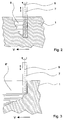
- Figures 2 and 3 illustrate the removal of the Workpiece material in different phases during the Machining the workpiece 1.
- the representation of the Figures 2 and 3 are in section from the side, wherein the viewing direction with respect to FIG. 1 from the left lies within the image plane.
- the situation in FIG. 2 corresponds approximately to the state at point B, the Situation of Fig. 3 roughly the state at point C.
- Both Fig. 2 and Fig. 3 are as are to be understood as a highly schematic representation in particular not to scale.
- the grinding pin 7 has several Feed steps the position shown in the workpiece 1 reached. Here he has the area 8 of the desired Contour worked out of workpiece 1. After one further feed step of the workpiece 1 in the direction V the grinding pin 7 now works a further section the contour out of the workpiece 1. For this he is using the tool spindle pivots, causing a movement in corresponds to the image plane in or out of it, and its depth in the workpiece is changed, which one Movement of the grinding pin up or down corresponds to the axis of rotation 9.
- the first load case is so-called front load case. This occurs when the grinding pin 7 along its axis of rotation in the Workpiece 1 is moved into it. A material removal takes place here only on the face of the grinding pin. There are different situations here. In the first situation, the entire face of the Part of the material removal. This is for Example if the case in Fig. 2 Grinding pin 7 down along its axis of rotation is moved. One can see a complete one here speak front load case. In the other situation only takes up part of the end face of the material removal part. This is the case, for example, if the Grinding pin 7 in Fig. 3 along its Direction of rotation is shifted down. Here 3 is only removed from the lower right End of the sharpening pencil.
- the first and simplest variant is the speed of the Relative movement between tool and workpiece on one limit low maximum value. With enough lower Choosing this speed leads to the fact that even in the worst case, no overloading of the Tool can be done. By doing so, one effectively overloads the tool prevent, however, the processing time of the Workpiece in an unacceptable manner.
- Tool load added. That way the movement between tool and workpiece in those areas in which a high stock removal rate is expected to be very slow from the start and vice versa in areas where only one low stock removal rate is expected to be higher Relative speed between tool and workpiece to get voted.
- the sequence of the method according to the invention is schematically illustrated in FIG. 4.
- the geometrical Data of the fitting body to be created are in one Computing and storage unit 10 stored.
- this data for example, on known Way from an optical 3D image of an area of Oral cavity can be obtained.
- From this geometric data calculates the computing and storage unit 10 on the one hand the path on which the machining tool and the Move the workpiece relative to each other and on the other hand for a number of points on this path the expected one Removal rate of the tool.
- the Computing and control unit 10 control signals therefrom passes them on to a control unit 11.
- the Control unit 11 regulates various electromotive, hydraulic or pneumatic Drives used to perform a relative movement are provided between the tool and the workpiece.
- these drives are schematic to one Drive unit 12 summarized.
- the control device 11 In addition to the Control signals from the computing and control device 10 the control device 11 also receives signals by a drive control 13, with the help of electromotive rotary drive 14 of the Machining tool is regulated. The regulation is done in such a way that the rotational frequency of the processing tool remains largely constant.
- the control unit 11 is then fed signals the information about the power consumption of the Rotary drive 14 included. From the signals of the Computing and control unit 10 on the one hand and the Drive control 13 on the other hand determines the Control unit 11 the necessary manipulated variables for Drive unit 12, which are required to Relative movement between tool and workpiece the calculated path.
- the web is in the computing and control device 10 first divided into a number of sections, during which there is no linear feed of the workpiece along the feed direction.
- For each Section can now calculate the point by point Swivel position of the tool and the calculation of the Depth of the tool in the workpiece.
- the path can thus be represented by a large number of triples of numbers, with the first numerical value each Tripels the track section, the second numerical value the Swivel position of the tool and the third numerical value indicates the depth of the tool in the workpiece. If that Workpiece additionally rotates around the feed axis carries out another numerical value for the Angle of rotation of the workpiece.
- the calculation of the baby data need not be for the Entire web completely before the start of the grinding process respectively. It can also be carried out in sections be, for example, during the grinding of a Track section for the next track section.
- the computing and control device 10 now conducts signals to the control unit 11, which are suitable for the Drive for pivoting the tool and the To control the change in depth of the tool.
- the Drive for example, contains stepper motors the computing and control device 10 to the Control device 11 information on the at each Number of adjustment steps to be carried out by the Stepper motor and the chronological order of these Adjustment steps.
- the chronological order of the Adjustment steps are laid in particular by Relative motion speed fixed. It will be like this chosen that this speed is close, but below the calculated maximum permissible speed.
- the control device 11 controls this Signals directly the drives for the Swiveling movement and the change in depth of the tool as well as the drive after the end of each rail section for the workpiece feed. It receives from the Control device 13 information about the current Load on the grinding pin. In optimal conditions, that is, with exact adjustment of the tools, one new and thus powerful grinding pen, more optimal Cooling etc. becomes the instantaneous load determined largely match the calculated load. The control device does not need in this case intervene. However, the grinding pin is worn and therefore less efficient than expected, or lie other non-optimal operating conditions, so the actual load on the grinding pin is higher than the calculated load. In this case, the Control device 11 regulating, in which it Relative speed between tool and workpiece lowers.
- the control method according to the invention can often without apparatus change to existing devices for Creation of medical fitting bodies implemented become.
- a device is in any case anyway comprise a computing and control device that After suitable programming, the functionality of the Take over computing and control device 10 of FIG. 4 can.
- the control unit for detection of overload. Instead of a fixed maximum Relative speed between workpiece and tool this control unit is now a variable maximum Relative speed given by the respective Path point is dependent. So can easily and a very reliable at low cost Scheme can be achieved.
Landscapes
- Health & Medical Sciences (AREA)
- Engineering & Computer Science (AREA)
- Mechanical Engineering (AREA)
- Life Sciences & Earth Sciences (AREA)
- Veterinary Medicine (AREA)
- Public Health (AREA)
- Oral & Maxillofacial Surgery (AREA)
- General Health & Medical Sciences (AREA)
- Animal Behavior & Ethology (AREA)
- Epidemiology (AREA)
- Dentistry (AREA)
- Orthopedic Medicine & Surgery (AREA)
- Geometry (AREA)
- Heart & Thoracic Surgery (AREA)
- Biomedical Technology (AREA)
- Transplantation (AREA)
- Cardiology (AREA)
- Manufacturing & Machinery (AREA)
- Vascular Medicine (AREA)
- Physics & Mathematics (AREA)
- Grinding And Polishing Of Tertiary Curved Surfaces And Surfaces With Complex Shapes (AREA)
- Constituent Portions Of Griding Lathes, Driving, Sensing And Control (AREA)
- Turning (AREA)
- Dental Preparations (AREA)
- Dental Prosthetics (AREA)
- Materials For Medical Uses (AREA)
Applications Claiming Priority (2)
| Application Number | Priority Date | Filing Date | Title |
|---|---|---|---|
| DE19930859A DE19930859A1 (de) | 1999-07-05 | 1999-07-05 | Verfahren zur Erstellung von medizinischen, insbesondere zahnmedizinischen Paßkörpern |
| DE19930859 | 1999-07-05 |
Publications (2)
| Publication Number | Publication Date |
|---|---|
| EP1066801A1 true EP1066801A1 (fr) | 2001-01-10 |
| EP1066801B1 EP1066801B1 (fr) | 2004-09-22 |
Family
ID=7913641
Family Applications (1)
| Application Number | Title | Priority Date | Filing Date |
|---|---|---|---|
| EP00114401A Expired - Lifetime EP1066801B1 (fr) | 1999-07-05 | 2000-07-05 | Procédé et dispositif pour fabriquer des prothèses médicales en particulier dentaires |
Country Status (5)
| Country | Link |
|---|---|
| US (1) | US6454629B1 (fr) |
| EP (1) | EP1066801B1 (fr) |
| JP (1) | JP4878074B2 (fr) |
| AT (1) | ATE276710T1 (fr) |
| DE (2) | DE19930859A1 (fr) |
Cited By (3)
| Publication number | Priority date | Publication date | Assignee | Title |
|---|---|---|---|---|
| WO2003041606A2 (fr) | 2001-11-15 | 2003-05-22 | 3M Espe Ag | Procede de production de prothese dentaire |
| WO2014039268A1 (fr) * | 2012-09-04 | 2014-03-13 | 3M Innovative Properties Company | Procédé de production d'une restauration dentaire |
| US10507090B2 (en) | 2014-08-12 | 2019-12-17 | Hangzhou Erran Technology Co., Ltd. | Dental all-ceramic restoration and manufacturing method thereof |
Families Citing this family (16)
| Publication number | Priority date | Publication date | Assignee | Title |
|---|---|---|---|---|
| DE10104287B4 (de) * | 2001-01-30 | 2006-08-24 | Sirona Dental Systems Gmbh | Verfahren zur Bestimmung aktueller Positionsdaten eines Bearbeitungswerkzeuges und Vorrichtung hierzu |
| US20100143867A1 (en) * | 2003-12-19 | 2010-06-10 | Cad.Esthetics Ab | method for producing a dental restoration |
| WO2005058184A1 (fr) * | 2003-12-19 | 2005-06-30 | Cad.Esthetics Ab | Procede de production d'une restauration dentaire |
| DE102004035970A1 (de) | 2004-07-23 | 2006-02-16 | Sirona Dental Systems Gmbh | Verfahren zur Bearbeitung eines digitalisierten Werkstücks, insbesondere von dreidimensionalen Modellen von herzustellenden Zahnersatzteilen und Vorrichtung |
| DE102005001600B4 (de) * | 2004-11-30 | 2011-08-18 | FOLLOW ME! Technology Systems GmbH, 81675 | Verfahren zur Material abtragenden Bearbeitung von Werkstücken und Werkstück bzw. Formelement |
| DE102005035474B4 (de) * | 2005-07-28 | 2019-06-13 | Institut Straumann Ag | Verfahren zum Herstellen von Zahnersatzteilen, Computer, Computerprogramm und computerlesbares Medium |
| ATE507796T1 (de) | 2007-06-07 | 2011-05-15 | Nobel Biocare Services Ag | Verfahren zur herstellung eines dentalen produkts |
| EP2014254B1 (fr) * | 2007-06-07 | 2018-10-31 | Nobel Biocare Services AG | Procédé et produit fritté pour former un bridge |
| US20090129882A1 (en) * | 2007-11-15 | 2009-05-21 | D4D Technologies, Llc | Methods, Systems, and Devices for Monitoring Tools in a Dental Milling Machine |
| EP2072020A1 (fr) * | 2007-12-17 | 2009-06-24 | Nobel Biocare Services AG | Procédé de fabrication d'un produit céramique dentaire |
| DE102010061116B4 (de) * | 2010-12-08 | 2022-01-13 | Helge Arndt | Verfahren zur Herstellung von dentalen Werkstücken |
| CN103083100B (zh) * | 2013-01-04 | 2016-01-20 | 深圳市翔通光电技术有限公司 | 一种齿科义齿加工方法及系统 |
| DE102017212168B4 (de) * | 2017-07-17 | 2019-08-29 | ModuleWorks GmbH | Verfahren zum Schleifen von Zahnprothesen oder Zahnersatz mit einer Mehrachs-Bearbeitungsmaschine |
| EP3653169B1 (fr) * | 2018-11-15 | 2023-08-02 | SIRONA Dental Systems GmbH | Procédé de production de pièces de prothèse dentaire en céramique, station d'usinage cad/cam, et ébauche en céramique dentaire à résistance finale |
| EP3764536A1 (fr) * | 2019-07-11 | 2021-01-13 | DENTSPLY SIRONA Inc. | Procédé de fonctionnement d'un moteur pas-à-pas dans une machine d'outil dentaire |
| EP3797733A1 (fr) * | 2019-09-24 | 2021-03-31 | DENTSPLY SIRONA Inc. | Procédé de planification de trajets d'outils de forme libre pour usinage simultané sur deux faces avec couplage d'axe cinématique |
Citations (6)
| Publication number | Priority date | Publication date | Assignee | Title |
|---|---|---|---|---|
| US4707793A (en) * | 1985-09-30 | 1987-11-17 | The Boeing Company | Method of determining feed rate and cutting speed for cutting metal and of predicting cutting effects |
| US4766704A (en) * | 1984-10-24 | 1988-08-30 | Marco Brandestini | Method and apparatus for the custom shaping of dental inlays, onlays, crowns, bridges and parts thereof |
| EP0455853A1 (fr) * | 1990-05-09 | 1991-11-13 | Siemens Aktiengesellschaft | Dispositif pour la fabrication de prothèses médicales, en particulier prothèses dentaires |
| US5083280A (en) * | 1989-01-26 | 1992-01-21 | Kabushiki Kaisha Okuma Tekkosho | Method for correcting tool feed rate in numerical control system and apparatus therefor |
| DE4030175A1 (de) * | 1990-09-24 | 1992-03-26 | Siemens Ag | Verfahren zum kalibrieren eines motorisch angetriebenen werkzeuges in bezug auf ein mit diesem zu bearbeitendes werkstueck sowie vorrichtung zur durchfuehrung des verfahrens |
| US5128870A (en) * | 1989-06-09 | 1992-07-07 | Regents Of The University Of Minnesota | Automated high-precision fabrication of objects of complex and unique geometry |
Family Cites Families (18)
| Publication number | Priority date | Publication date | Assignee | Title |
|---|---|---|---|---|
| US4264308A (en) * | 1978-09-29 | 1981-04-28 | Asami Tanaka | Dental method for fabricating restorations |
| US4237408A (en) * | 1979-08-10 | 1980-12-02 | Cincinnati Milacron Inc. | Method and apparatus for modifying the operation of a machine tool as a function of torque |
| DE3003435A1 (de) * | 1980-01-31 | 1981-08-06 | Becker Dental-Labor Gmbh, 5100 Aachen | Verfahren und vorrichtung zur herstellung eines kronenteiles |
| JPS61226206A (ja) * | 1985-04-01 | 1986-10-08 | Hitachi Maxell Ltd | 超音波ロ−タリ−加工機 |
| JPH01264769A (ja) * | 1988-04-11 | 1989-10-23 | Daido Steel Co Ltd | 帯鋼連続表面研磨方法 |
| EP0455855B1 (fr) * | 1990-05-09 | 1995-04-12 | Siemens Aktiengesellschaft | Procédé et dispositif pour fabriquer des prothèses médicales en particulier dentaires |
| JPH04152011A (ja) * | 1990-10-11 | 1992-05-26 | Eisuke Yokoyama | スムースプロフィル加工システム |
| DE4332065C2 (de) * | 1992-09-24 | 1998-07-09 | Thera Ges Fuer Patente | Ultraschallbearbeitungsvorrichtung und Verfahren zur Bearbeitung von Werkstücken mittels der Ultraschallbearbeitungsvorrichtung |
| US5310342A (en) * | 1993-02-19 | 1994-05-10 | Bernstein Stuart H | Rotary tool for shaping replacement teeth |
| JPH07132440A (ja) * | 1993-11-02 | 1995-05-23 | Fanuc Ltd | 加工負荷監視方式 |
| JPH0938845A (ja) * | 1995-07-27 | 1997-02-10 | Fanuc Ltd | 数値制御装置 |
| JP3264607B2 (ja) * | 1995-07-28 | 2002-03-11 | 株式会社モリタ製作所 | 歯科用ハンドピースのモータ制御装置 |
| JPH09155712A (ja) * | 1995-11-30 | 1997-06-17 | Ricoh Co Ltd | 加工装置 |
| JPH106182A (ja) * | 1996-06-20 | 1998-01-13 | Nikon Corp | 加工方法及び加工装置 |
| JPH106143A (ja) * | 1996-06-25 | 1998-01-13 | Advance Co Ltd | 塊状物切削加工方法及び同方法を用いた装置 |
| US5743686A (en) * | 1996-11-18 | 1998-04-28 | Montgomery; Riley B. | Pattern sizing tool |
| ATE287317T1 (de) * | 1997-03-15 | 2005-02-15 | Makino Milling Machine | Prozessor für maschinelle bearbeitung |
| JPH10293605A (ja) * | 1997-04-18 | 1998-11-04 | Yamazaki Mazak Corp | 工作機械における主軸負荷表示装置 |
-
1999
- 1999-07-05 DE DE19930859A patent/DE19930859A1/de not_active Withdrawn
-
2000
- 2000-07-03 JP JP2000201371A patent/JP4878074B2/ja not_active Expired - Lifetime
- 2000-07-05 DE DE50007847T patent/DE50007847D1/de not_active Expired - Lifetime
- 2000-07-05 AT AT00114401T patent/ATE276710T1/de active
- 2000-07-05 US US09/610,358 patent/US6454629B1/en not_active Expired - Lifetime
- 2000-07-05 EP EP00114401A patent/EP1066801B1/fr not_active Expired - Lifetime
Patent Citations (6)
| Publication number | Priority date | Publication date | Assignee | Title |
|---|---|---|---|---|
| US4766704A (en) * | 1984-10-24 | 1988-08-30 | Marco Brandestini | Method and apparatus for the custom shaping of dental inlays, onlays, crowns, bridges and parts thereof |
| US4707793A (en) * | 1985-09-30 | 1987-11-17 | The Boeing Company | Method of determining feed rate and cutting speed for cutting metal and of predicting cutting effects |
| US5083280A (en) * | 1989-01-26 | 1992-01-21 | Kabushiki Kaisha Okuma Tekkosho | Method for correcting tool feed rate in numerical control system and apparatus therefor |
| US5128870A (en) * | 1989-06-09 | 1992-07-07 | Regents Of The University Of Minnesota | Automated high-precision fabrication of objects of complex and unique geometry |
| EP0455853A1 (fr) * | 1990-05-09 | 1991-11-13 | Siemens Aktiengesellschaft | Dispositif pour la fabrication de prothèses médicales, en particulier prothèses dentaires |
| DE4030175A1 (de) * | 1990-09-24 | 1992-03-26 | Siemens Ag | Verfahren zum kalibrieren eines motorisch angetriebenen werkzeuges in bezug auf ein mit diesem zu bearbeitendes werkstueck sowie vorrichtung zur durchfuehrung des verfahrens |
Cited By (10)
| Publication number | Priority date | Publication date | Assignee | Title |
|---|---|---|---|---|
| WO2003041606A2 (fr) | 2001-11-15 | 2003-05-22 | 3M Espe Ag | Procede de production de prothese dentaire |
| DE10156156A1 (de) * | 2001-11-15 | 2003-06-05 | 3M Espe Ag | Verfahren zur Herstellung von Zahnersatz |
| WO2003041606A3 (fr) * | 2001-11-15 | 2004-02-26 | 3M Espe Ag | Procede de production de prothese dentaire |
| DE10156156B4 (de) * | 2001-11-15 | 2005-04-21 | 3M Espe Ag | Verfahren zur Herstellung von Zahnersatz |
| AU2002363593B2 (en) * | 2001-11-15 | 2007-01-04 | 3M Espe Ag | Method for producing dentures |
| US7431545B2 (en) | 2001-11-15 | 2008-10-07 | 3M Espe Ag | Method for producing dentures |
| CN100431503C (zh) * | 2001-11-15 | 2008-11-12 | 3M埃斯佩股份公司 | 制造假牙的方法 |
| WO2014039268A1 (fr) * | 2012-09-04 | 2014-03-13 | 3M Innovative Properties Company | Procédé de production d'une restauration dentaire |
| US10040134B2 (en) | 2012-09-04 | 2018-08-07 | 3M Innovative Properties Company | Method of producing a dental restoration |
| US10507090B2 (en) | 2014-08-12 | 2019-12-17 | Hangzhou Erran Technology Co., Ltd. | Dental all-ceramic restoration and manufacturing method thereof |
Also Published As
| Publication number | Publication date |
|---|---|
| ATE276710T1 (de) | 2004-10-15 |
| DE50007847D1 (de) | 2004-10-28 |
| JP4878074B2 (ja) | 2012-02-15 |
| JP2001054863A (ja) | 2001-02-27 |
| EP1066801B1 (fr) | 2004-09-22 |
| DE19930859A1 (de) | 2001-01-18 |
| US6454629B1 (en) | 2002-09-24 |
Similar Documents
| Publication | Publication Date | Title |
|---|---|---|
| EP1066801B1 (fr) | Procédé et dispositif pour fabriquer des prothèses médicales en particulier dentaires | |
| EP1443869B1 (fr) | Procede de production de prothese dentaire | |
| EP3299105B1 (fr) | Procédé de chanfreinage des roues dentées coniques | |
| EP2237122B1 (fr) | Procédé et dispositif de production de données de commande destinées à commander un outil sur une machine-outil | |
| DE69732808T2 (de) | Schleifvorrichtung | |
| EP2823924A2 (fr) | Machine à dresser double | |
| EP1060712B1 (fr) | Dispositif et procédé de fabrication de prothèses dentaires | |
| EP3552743A1 (fr) | Dispositif et procédé de traitement par chanfreinage d'une pièce à dents à usiner | |
| EP1864739A1 (fr) | Dispositif et procédé d'usinage avant traitement de roues coniques | |
| EP3439819A1 (fr) | Procédé d'enlèvement de matière d'une arête frontale de denture d'engrenage et dispositif conçu à cet effet | |
| DE202004004480U1 (de) | Kegelrad-Verzahnmaschine zum Anfasen und/oder Entgraten von Kanten an den Zähnen eines Kegelrades | |
| EP1005940B1 (fr) | Méthode et appareil pour le contrôle d'une machine pour enfonçage par électroérosion | |
| EP3584025A1 (fr) | Procédé de rectification topologique de denture par génération d'une pièce de roue dentée et machine de rectification dotée d'une commande de rectification topologique de denture par génération d'une pièce de roue dentée | |
| DE2940444C2 (de) | Kopiersteuerungsvorrichtung für eine Kopierfräsmaschine mit Werkzeugwechseleinrichtung | |
| DE69412490T2 (de) | Verfahren zum schärfen von schneidklingen | |
| EP1760562B1 (fr) | Procédé destiné au contrôle adaptatif de l' avance sur des machines-outils en commande numérique | |
| EP0293673B1 (fr) | Procédé et dispositif de meulage mécanique de pièces au moyen d'outils électriquement conducteurs | |
| DE3411113A1 (de) | Verfahren zum bestimmen der abnutzung von werkzeugen | |
| DE10230148C5 (de) | Verfahren zum Bearbeiten von mittels Wälzfräsen hergestellten Zahnrädern | |
| EP1019215B1 (fr) | Machine pour l'usinage de pieces avec des dents coupantes, notamment des lames de scie | |
| EP1019219B1 (fr) | Dispositif de mesure sur une machine destinee a l'usinage de pieces avec des dents coupantes, notamment des lames de scie | |
| DE102020000882A1 (de) | Verfahren zum Herstellen eines Werkstücks, insbesondere einer Turbinenschaufel, mit einem Fräswerkzeug | |
| DE202008008212U1 (de) | Kegelradverzahnmaschine zum Verzahnen und Entgraten eines Kegelrades | |
| DE19804762B4 (de) | Verfahren und Vorrichtung zum Schleifen der Frei-, Span- und/oder Brustfläche von Zähnen eines Sägewerkzeugs | |
| DE2235690A1 (de) | Konusschaftfraeser sowie maschine und verfahren zu seiner herstellung |
Legal Events
| Date | Code | Title | Description |
|---|---|---|---|
| PUAI | Public reference made under article 153(3) epc to a published international application that has entered the european phase |
Free format text: ORIGINAL CODE: 0009012 |
|
| AK | Designated contracting states |
Kind code of ref document: A1 Designated state(s): AT BE CH CY DE DK ES FI FR GB GR IE IT LI LU MC NL PT SE |
|
| AX | Request for extension of the european patent |
Free format text: AL;LT;LV;MK;RO;SI |
|
| 17P | Request for examination filed |
Effective date: 20001208 |
|
| AKX | Designation fees paid |
Free format text: AT BE CH CY DE DK ES FI FR GB GR IE IT LI LU MC NL PT SE |
|
| 17Q | First examination report despatched |
Effective date: 20030708 |
|
| GRAP | Despatch of communication of intention to grant a patent |
Free format text: ORIGINAL CODE: EPIDOSNIGR1 |
|
| GRAS | Grant fee paid |
Free format text: ORIGINAL CODE: EPIDOSNIGR3 |
|
| GRAA | (expected) grant |
Free format text: ORIGINAL CODE: 0009210 |
|
| AK | Designated contracting states |
Kind code of ref document: B1 Designated state(s): AT BE CH CY DE DK ES FI FR GB GR IE IT LI LU MC NL PT SE |
|
| PG25 | Lapsed in a contracting state [announced via postgrant information from national office to epo] |
Ref country code: IT Free format text: LAPSE BECAUSE OF FAILURE TO SUBMIT A TRANSLATION OF THE DESCRIPTION OR TO PAY THE FEE WITHIN THE PRESCRIBED TIME-LIMIT;WARNING: LAPSES OF ITALIAN PATENTS WITH EFFECTIVE DATE BEFORE 2007 MAY HAVE OCCURRED AT ANY TIME BEFORE 2007. THE CORRECT EFFECTIVE DATE MAY BE DIFFERENT FROM THE ONE RECORDED. Effective date: 20040922 Ref country code: FI Free format text: LAPSE BECAUSE OF FAILURE TO SUBMIT A TRANSLATION OF THE DESCRIPTION OR TO PAY THE FEE WITHIN THE PRESCRIBED TIME-LIMIT Effective date: 20040922 Ref country code: IE Free format text: LAPSE BECAUSE OF FAILURE TO SUBMIT A TRANSLATION OF THE DESCRIPTION OR TO PAY THE FEE WITHIN THE PRESCRIBED TIME-LIMIT Effective date: 20040922 Ref country code: NL Free format text: LAPSE BECAUSE OF FAILURE TO SUBMIT A TRANSLATION OF THE DESCRIPTION OR TO PAY THE FEE WITHIN THE PRESCRIBED TIME-LIMIT Effective date: 20040922 Ref country code: ES Free format text: LAPSE BECAUSE OF FAILURE TO SUBMIT A TRANSLATION OF THE DESCRIPTION OR TO PAY THE FEE WITHIN THE PRESCRIBED TIME-LIMIT Effective date: 20040922 |
|
| REG | Reference to a national code |
Ref country code: GB Ref legal event code: FG4D Free format text: NOT ENGLISH |
|
| REG | Reference to a national code |
Ref country code: CH Ref legal event code: EP |
|
| REG | Reference to a national code |
Ref country code: CH Ref legal event code: NV Representative=s name: WILLIAM BLANC & CIE CONSEILS EN PROPRIETE INDUSTRI |
|
| REG | Reference to a national code |
Ref country code: IE Ref legal event code: FG4D Free format text: GERMAN |
|
| REF | Corresponds to: |
Ref document number: 50007847 Country of ref document: DE Date of ref document: 20041028 Kind code of ref document: P |
|
| PG25 | Lapsed in a contracting state [announced via postgrant information from national office to epo] |
Ref country code: DK Free format text: LAPSE BECAUSE OF FAILURE TO SUBMIT A TRANSLATION OF THE DESCRIPTION OR TO PAY THE FEE WITHIN THE PRESCRIBED TIME-LIMIT Effective date: 20041222 Ref country code: GR Free format text: LAPSE BECAUSE OF FAILURE TO SUBMIT A TRANSLATION OF THE DESCRIPTION OR TO PAY THE FEE WITHIN THE PRESCRIBED TIME-LIMIT Effective date: 20041222 Ref country code: SE Free format text: LAPSE BECAUSE OF FAILURE TO SUBMIT A TRANSLATION OF THE DESCRIPTION OR TO PAY THE FEE WITHIN THE PRESCRIBED TIME-LIMIT Effective date: 20041222 |
|
| GBT | Gb: translation of ep patent filed (gb section 77(6)(a)/1977) |
Effective date: 20050116 |
|
| NLV1 | Nl: lapsed or annulled due to failure to fulfill the requirements of art. 29p and 29m of the patents act | ||
| REG | Reference to a national code |
Ref country code: IE Ref legal event code: FD4D |
|
| PG25 | Lapsed in a contracting state [announced via postgrant information from national office to epo] |
Ref country code: LU Free format text: LAPSE BECAUSE OF NON-PAYMENT OF DUE FEES Effective date: 20050705 Ref country code: CY Free format text: LAPSE BECAUSE OF FAILURE TO SUBMIT A TRANSLATION OF THE DESCRIPTION OR TO PAY THE FEE WITHIN THE PRESCRIBED TIME-LIMIT Effective date: 20050705 |
|
| PLBE | No opposition filed within time limit |
Free format text: ORIGINAL CODE: 0009261 |
|
| STAA | Information on the status of an ep patent application or granted ep patent |
Free format text: STATUS: NO OPPOSITION FILED WITHIN TIME LIMIT |
|
| PG25 | Lapsed in a contracting state [announced via postgrant information from national office to epo] |
Ref country code: MC Free format text: LAPSE BECAUSE OF NON-PAYMENT OF DUE FEES Effective date: 20050731 Ref country code: BE Free format text: LAPSE BECAUSE OF NON-PAYMENT OF DUE FEES Effective date: 20050731 |
|
| 26N | No opposition filed |
Effective date: 20050623 |
|
| ET | Fr: translation filed | ||
| BERE | Be: lapsed |
Owner name: *SIRONA DENTAL SYSTEMS G.M.B.H. Effective date: 20050731 |
|
| PG25 | Lapsed in a contracting state [announced via postgrant information from national office to epo] |
Ref country code: PT Free format text: LAPSE BECAUSE OF NON-PAYMENT OF DUE FEES Effective date: 20050222 |
|
| REG | Reference to a national code |
Ref country code: CH Ref legal event code: PFA Owner name: SIRONA DENTAL SYSTEMS GMBH Free format text: SIRONA DENTAL SYSTEMS GMBH#FABRIKSTRASSE 31#64625 BENSHEIM (DE) -TRANSFER TO- SIRONA DENTAL SYSTEMS GMBH#FABRIKSTRASSE 31#64625 BENSHEIM (DE) |
|
| REG | Reference to a national code |
Ref country code: CH Ref legal event code: PCAR Free format text: NOVAGRAAF SWITZERLAND SA;CHEMIN DE L'ECHO 3;1213 ONEX (CH) |
|
| REG | Reference to a national code |
Ref country code: FR Ref legal event code: PLFP Year of fee payment: 16 |
|
| REG | Reference to a national code |
Ref country code: FR Ref legal event code: PLFP Year of fee payment: 17 |
|
| REG | Reference to a national code |
Ref country code: FR Ref legal event code: PLFP Year of fee payment: 18 |
|
| REG | Reference to a national code |
Ref country code: FR Ref legal event code: PLFP Year of fee payment: 19 |
|
| PGFP | Annual fee paid to national office [announced via postgrant information from national office to epo] |
Ref country code: FR Payment date: 20180724 Year of fee payment: 19 Ref country code: DE Payment date: 20180730 Year of fee payment: 19 |
|
| PGFP | Annual fee paid to national office [announced via postgrant information from national office to epo] |
Ref country code: CH Payment date: 20180724 Year of fee payment: 19 Ref country code: AT Payment date: 20180730 Year of fee payment: 19 Ref country code: GB Payment date: 20180724 Year of fee payment: 19 |
|
| REG | Reference to a national code |
Ref country code: DE Ref legal event code: R119 Ref document number: 50007847 Country of ref document: DE |
|
| REG | Reference to a national code |
Ref country code: CH Ref legal event code: PL |
|
| REG | Reference to a national code |
Ref country code: AT Ref legal event code: MM01 Ref document number: 276710 Country of ref document: AT Kind code of ref document: T Effective date: 20190705 |
|
| GBPC | Gb: european patent ceased through non-payment of renewal fee |
Effective date: 20190705 |
|
| PG25 | Lapsed in a contracting state [announced via postgrant information from national office to epo] |
Ref country code: DE Free format text: LAPSE BECAUSE OF NON-PAYMENT OF DUE FEES Effective date: 20200201 Ref country code: GB Free format text: LAPSE BECAUSE OF NON-PAYMENT OF DUE FEES Effective date: 20190705 Ref country code: AT Free format text: LAPSE BECAUSE OF NON-PAYMENT OF DUE FEES Effective date: 20190705 |
|
| PG25 | Lapsed in a contracting state [announced via postgrant information from national office to epo] |
Ref country code: CH Free format text: LAPSE BECAUSE OF NON-PAYMENT OF DUE FEES Effective date: 20190731 Ref country code: LI Free format text: LAPSE BECAUSE OF NON-PAYMENT OF DUE FEES Effective date: 20190731 |
|
| PG25 | Lapsed in a contracting state [announced via postgrant information from national office to epo] |
Ref country code: FR Free format text: LAPSE BECAUSE OF NON-PAYMENT OF DUE FEES Effective date: 20190731 |