EP1066906A2 - Verfahren zur Messung von mit Kreissägeblättern verbundenen Karakteristiken und Vorrichtung zur genauen Ausrichtung von Kreissägeblatt und Vorritzwerkzeug - Google Patents
Verfahren zur Messung von mit Kreissägeblättern verbundenen Karakteristiken und Vorrichtung zur genauen Ausrichtung von Kreissägeblatt und Vorritzwerkzeug Download PDFInfo
- Publication number
- EP1066906A2 EP1066906A2 EP00114563A EP00114563A EP1066906A2 EP 1066906 A2 EP1066906 A2 EP 1066906A2 EP 00114563 A EP00114563 A EP 00114563A EP 00114563 A EP00114563 A EP 00114563A EP 1066906 A2 EP1066906 A2 EP 1066906A2
- Authority
- EP
- European Patent Office
- Prior art keywords
- saw
- notching tool
- pack
- notching
- teeth
- Prior art date
- Legal status (The legal status is an assumption and is not a legal conclusion. Google has not performed a legal analysis and makes no representation as to the accuracy of the status listed.)
- Granted
Links
Images


Classifications
-
- B—PERFORMING OPERATIONS; TRANSPORTING
- B23—MACHINE TOOLS; METAL-WORKING NOT OTHERWISE PROVIDED FOR
- B23D—PLANING; SLOTTING; SHEARING; BROACHING; SAWING; FILING; SCRAPING; LIKE OPERATIONS FOR WORKING METAL BY REMOVING MATERIAL, NOT OTHERWISE PROVIDED FOR
- B23D45/00—Sawing machines or sawing devices with circular saw blades or with friction saw discs
- B23D45/10—Sawing machines or sawing devices with circular saw blades or with friction saw discs with a plurality of circular saw blades
- B23D45/105—Sawing machines or sawing devices with circular saw blades or with friction saw discs with a plurality of circular saw blades operating within the same plane
-
- B—PERFORMING OPERATIONS; TRANSPORTING
- B23—MACHINE TOOLS; METAL-WORKING NOT OTHERWISE PROVIDED FOR
- B23D—PLANING; SLOTTING; SHEARING; BROACHING; SAWING; FILING; SCRAPING; LIKE OPERATIONS FOR WORKING METAL BY REMOVING MATERIAL, NOT OTHERWISE PROVIDED FOR
- B23D59/00—Accessories specially designed for sawing machines or sawing devices
- B23D59/001—Measuring or control devices, e.g. for automatic control of work feed pressure on band saw blade
- B23D59/002—Measuring or control devices, e.g. for automatic control of work feed pressure on band saw blade for the position of the saw blade
Definitions
- the present invention relates to a method of measuring the characteristics of circular saws.
- the present invention also relates to a device for accurately aligning a circular saw and associated notching tool, both used on a panel cutting machine.
- Wood panels or similar are normally cut on machines comprising a frame approximately the same size as, but no smaller than, the panels for cutting; a straight guide integral with one edge of the frame and extending in a given horizontal direction; a carriage running along the guide; and a cutting unit mounted on the carriage to cut the panels parallel to said horizontal direction.
- the cutting unit normally comprises a circular saw, which projects from a longitudinal gap formed in a horizontal bed integral with the frame on which a pack of panels is placed, so as to cut the pack in a vertical plane parallel to the horizontal traveling direction of the carriage.
- the pack is clamped, during the cutting operation, by pressure members; and the circular saw is powered by a drive unit, which, to reduce width, is supported on the carriage, beneath the saw, and is connected to the saw by a speed reducer, e.g. a belt reducer.
- Cutting machines of the above type normally comprise a notching tool - also in the form of a circular saw, but much smaller in diameter than the one used to cut the pack of panels - which, as the carriage moves towards the pack of panels, precedes the circular saw to cut a groove in the underside surface of the pack.
- This is particularly desirable in the case of veneered chipboard panels, to enable the circular saw to work its way out of the pack without chipping the edges of the cut made by the saw. That is, any panels on the top or within the pack are gripped firmly between the pressure member and the work table, so that the topside surface of each panel effectively supports the underside surface of the panel on top, thus ensuring a clean cut.
- the underside surface of the bottom panel in the pack lies directly on the work table, astride the cutting gap in the table, and is therefore particularly susceptible to chipping by the saw as this works its way out of the pack.
- the bottom panel is invariably cut poorly, especially, as stated, in the case of veneered chipboard.
- most cutting machines are therefore equipped with notching tools for cutting a groove and so preventing chipping of the edges of the cut made in the underside surface of the bottom panel in the pack.
- the notching tool rotates in the opposite direction to the circular saw, and normally cuts the bottom panel to a depth of a couple of millimeters. Problems are encountered, however, in aligning the circular saw with the notching tool. That is, to achieve the desired effect, the cut made by the circular saw must be located within and perfectly centered with respect to the groove made by the notching tool on the underside surface of the pack.
- the groove made by the notching tool must be 0.05 mm wider on both sides with respect to the cut made by the circular saw, but not much wider than the saw blade, to avoid forming a step on the underside surface of the panel, which would ultimately lead to problems at the panel finishing (e.g. edging) stage.
- Alignment is normally done manually by the operator making a number of test cuts, and is therefore considerably time-consuming, considering that, on this type of machine, the circular saw is changed every 2-3 hours, and manually aligning the saw with the notching tool normally takes 15-20 minutes.
- Number 1 in Figure 1 indicates as a whole a cutting machine for cutting panels 2 - preferably, but not necessarily, wood panels, even of considerable size and weight - stacked neatly to form thick packs 3.
- Machine 1 comprises a frame 4, in turn, comprising two vertical supporting posts 5, and a work supporting beam 6 integral with posts 5 and having a substantially horizontal axis 6a.
- Machine 1 also comprises a tool carriage 7 mounted to run along beam 6 in a direction 8 parallel to axis 6a of beam 6. More specifically, beam 6 is fitted laterally with a guide device 10 for guiding carriage 7 and defined by two longitudinal guides 11 integral with beam 6 and both extending parallel to axis 6a along the full length of beam 6.
- Guide device 10 also comprises a rack 12, which is integral with beam 6, is located between and extends parallel to guides 11, and cooperates with an actuating device 13 carried by and for powering carriage 7.
- frame 4 also comprises a horizontal work table 14 onto which panels 2 are loaded.
- Table 14 is fixed to the top of beam 6, between vertical posts 5, and has a longitudinal gap 15 ( Figure 2) extending the full length of table 14, parallel to axis 6a, and defining the cutting plane of panels 2.
- Actuating device 13 moves carriage 7 along beam 6 to and from a rest position - to the right in Figure 1 - in which carriage 7 is located at an end portion of beam 6 to enable panels 2 to be loaded and unloaded on and off work table 14, and to enable, when necessary, manual or automatic replacement of the tools on carriage 7.
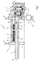
- tool carriage 7 comprises a box-type supporting frame 16, which is mounted to slide along guides 11 and is fitted integrally with actuating device 13 of carriage 7; and a cutting unit 17 carried by box frame 16 and in turn comprising a vertical plate 21 supporting two slides 22 and 23 moved in a vertical direction 20 by respective actuating devices 24 and 25.
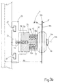
- plate 21 comprises a respective pair of dovetail guides 26, 27 (figures 3a, 3b) for supporting and guiding respective slide 22, 23 in direction 20.
- Device 24 comprises an electric motor 28 fitted to plate 21; a worm 29 extending in direction 20 and fitted to the drive shaft of motor 28; and an internally threaded vertical sleeve 30 integral with and projecting from slide 22, and engaged internally by worm 29.
- device 25 Via the worm 29-sleeve 30 coupling, rotation of the drive shaft of motor 28 moves slide 22 in direction 20.
- device 25 comprises an electric motor 31 fitted to plate 21; a worm 32 extending in direction 20 and fitted to the drive shaft of motor 31; and an internally threaded vertical sleeve 33 integral with and projecting from slide 23, and engaged internally by worm 32.
- Slide 22 is fitted with two projecting shafts 34 and 35 with respective horizontal axes perpendicular to direction 8.
- Shaft 35 is the drive shaft of an electric motor 36 fitted to slide 22, is lower than shaft 34, and transmits power to shaft 34 via a transmission device 37 defined by a pulley 38 fitted to shaft 34, a pulley 39 fitted to shaft 35, and a transmission belt 40 fitted between pulleys 38 and 39.
- Shaft 34 is fitted with a spindle 41 in turn fitted with a rotary tool 42 defined by a circular saw for cutting panels 2 in a plane perpendicular to the axis 34a of rotation of shaft 34.
- Slide 23 is fitted with two projecting shafts 43 and 44 with respective horizontal axes perpendicular to direction 8.
- Shaft 44 is the drive shaft of an electric motor 45 fitted to slide 23, is lower than shaft 43, and transmits power to shaft 43 via a transmission device 46 defined by a pulley 47 fitted to shaft 43, a pulley 48 fitted to shaft 44, and a transmission belt 49 fitted between pulleys 47 and 48.
- Shaft 43 is fitted with a spindle 50 in turn fitted with a rotary tool 51 defined by a circular saw or so-called notching tool for notching panels 2, before they are cut by saw 42, in a plane perpendicular to the axis 43a of rotation of shaft 43.
- Notching tool 51 is rotated by motor 45 in the opposite direction to saw 42.
- saw 42 rotates anticlockwise, and notching tool 51 clockwise.
- Slides 22 and 23 are therefore movable in direction 20, so that respective predetermined portions of saw 42 and notching tool 51 project from work table 14 and run along gap 15 to cut panels 2, and so that the portion of circular saw 42 projecting from work table 14 can be adjusted according to the height of pack 3 of panels 2 on work table 14, and the portion of notching tool 51 projecting from table 14 can be adjusted according to the required notching depth.
- Machine 1 also comprises a control unit 60, which has an operator control panel 61 for entering the operating parameters of machine 1, and controls actuating device 13 of carriage 7, actuating devices 24, 25 of slides 22, 23, and motors 36, 45 via an electronic central control unit 62.
- control unit 60 which has an operator control panel 61 for entering the operating parameters of machine 1, and controls actuating device 13 of carriage 7, actuating devices 24, 25 of slides 22, 23, and motors 36, 45 via an electronic central control unit 62.
- machine 1 also comprises a device 100, in accordance with the present invention, for accurately aligning any circular saw 42 and associated notching tool 51.
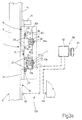
- device 100 according to the present invention comprises at least one detecting device 63 fitted to frame 4 of machine 1 and facing a lateral surface 42a of saw 42 and a lateral surface 51a of notching tool 51.
- Detecting device 63 provides for determining the distance between itself and lateral surface 42a of saw 42, and between itself and lateral surface 51a of notching tool 51, and supplies control unit 60 with a signal proportional to the distance detected.
- Detecting device 63 is preferably, but not necessarily, a position sensor, which directs a laser beam onto lateral surface 42a of saw 42 to determine the distance d1 - as saw 42 travels past device 63 - between device 63 and each tooth 42b on saw 42. Similarly, the same detecting device 63 determines the distance d2 ( Figure 3a) between itself and each tooth 51b on notching tool 51, as tool 51 travels past device 63. In other words, device 63, by determining the distance between itself and lateral surface 42a of saw 42, and the distance between itself and each tooth 42b on saw 42, calculates by how much the side of each tooth 42b deviates from lateral surface 42a of saw 42, and likewise for the teeth 51b on notching tool 51.
- Laser device 63 may, of course, be replaced by a LED or ultrasonic device, by a videocamera, or by a tracer device; and distance d1 (particularly in the case of large-diameter saws) may obviously differ from one tooth 42b to another on the same saw 42. This is due to incorrect tensioning of saw 42 resulting in deformation of the main body of saw 42, or to other factors intrinsic to the complex construction of saws in general; and each tooth 42b may deviate, with respect to a nominal reference plane, either away from or towards device 63.
- each tooth 51b on notching tool 51 may also be made of each tooth 51b on notching tool 51, to determine the actual distance d2 between the tooth and device 63; and the d1 and d2 values of each tooth 42b and 51b respectively are sent to control unit 60, which processes this as well as the other data mentioned previously.
- device 100 may also comprise a similar device 64 also integral with frame 4 of machine 1, located on the opposite side of saw 42 and notching tool 51 with respect to device 63, and for determining the same parameters as device 63, but relative, obviously, to the lateral surfaces 42c, 51c opposite surfaces 42a, 51a.
- Processing the parameters determined by devices 63 and 64 obviously provides for determining a further parameter, i.e. the thickness, of each tooth 42b, 51b.
- processing the data of devices 63 and 64 obviously also provides for determining, not only the thickness of tooth 51b but also any taper or other parameters indicated later on.
- detecting the deviation of each tooth 42b, and possibly of each tooth 51b provides for determining corresponding movements of notching tool 51 along axis 43a and, possibly, in vertical direction 20.
- slide 23 supports a device 71 for moving notching tool 51 parallel to itself along axis 43a.
- Device 71 is controlled by central control unit 62, and comprises an electric motor 72, the drive shaft of which is fitted with an externally threaded shaft 73 of axis 43a; electric motor 72 is supported by slide 23 and located between slide 23 and plate 21; shaft 43 is defined by two axially-connected, angularly-disconnected portions 74 and 75; portion 74 comprises a first portion 74a on which pulley 47 is formed, and a second portion 74b supporting spindle 50; portion 75 comprises an externally splined, internally threaded first sleeve portion 75a engaged by shaft 73, and a second portion 75b extending, via the interposition of ball bearings 76, inside a dead hole 77 formed in first portion 74a of portion 74; slide 23 supports an internally splined sleeve 78 engaged by first portion 75a of portion 75; and,
- motor 72 may be replaced by a knob for manually adjusting the position of notching tool 51 along axis 43a; and a similar knob may obviously also be used in place of motor 31 to move notching tool 51 manually in direction 20.
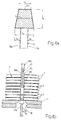
- control unit 60 can calculate the actual width 11 ( Figures 5a and 5b) of the cut 84 that will be made by saw 42, and therefore also how far notching tool 51 must be moved along axis 43a to obtain a groove 85 of width 12, and with respect to which cut 84 is centered perfectly.
- Figures 6a and 6b show the situation in which cut 84 made by saw 42 is off-centered with respect to groove 85. This is an anomalous configuration, also in view of the fact that, in extreme situations, i.e. with notching tool 51 misaligned with respect to saw 42, cut 84 may even be outside groove 85 altogether, so that the saw comes out directly through the underside surface 3a of pack 3, with all the obvious negative consequences described previously as regards chipping of the edges of cut 84.
- notching tool 51 when using a trapezoidal-section notching tool 51 as shown in Figures 4a and 4b, to align the notching tool 51 with a number of saws 42 of widely differing thicknesses, notching tool 51 must also be moved vertically with respect to plate 21 ( Figure 1) by means of device 25.
- the width 1 of groove 85 by raising or lowering notching tool 51, it is possible to adjust the width 1 of groove 85 by exploiting the trapezoidal shape of the tooth 51b section.
- the minimum and maximum widths l of groove 85 obviously equal the minimum and maximum widths S1 and S2 respectively of the tooth 51b section.
- S is the thickness of teeth 42b
- A is the deviation of tooth 42b from surface 42a of saw 42
- I is the thickness of tooth 51b of notching tool 51 to be calculated
- notching tool 51 must be moved 0.1 mm (the difference between 2.1 and 2 mm) away from frame 4 along axis 43a, and moved in direction 20 so that the thickness I of the part of tooth 51b determining groove 85 equals 4.5 mm.
- measurements may obviously be made of either all or only a limited number of teeth 42b of saw 42.
- the distance between surfaces 42a and 51a may be determined automatically by means of device 63 (64) or other means, and the tools aligned by processing the above measurements, as opposed to using specimen tools.
- machine 1 may be loaded later with an electronic file containing the parameters of a set of saws 42 related to a given notching tool 51, to enable machine 1 - obviously equipped with a similar device 100 for simply aligning notching tool 51 - to align notching tool 51 accurately according to the instructions in the electronic file.
- device 100 may also be used to check teeth 51b of notching tool 51, to determine, for example, whether teeth 51b all have the same geometric characteristics, such as ( Figure 4a): the width S1 of the top of tooth 51b; the width S2 of the base of tooth 51b; the deviations S3 and S4 of the apexes of tooth 51b from reference surfaces 51a and 51c of notching tool 51; the height h and taper of tooth 51b; and the thickness 1 of tooth 51b, even the point-to-point thickness from the base to the top of the tooth. All these parameters may be determined directly or by data processing. Whichever the case, the possibility of moving notching tool 51 in direction 20 provides for making various measurements of the same tooth 51b. All the above considerations relative to notching tool 51 obviously also apply to saw 42.
- the temporary rest position of carriage 7 may be used to check saw 42 and/or notching tool 51 and align notching tool 51 in real time with respective saw 42, taking into account any structural variations occurring during use of saw 42 and/or notching tool 51.
- Device 100 is particularly suitable for use on cutting machines 1 equipped with systems for automatically changing saws 42 and/or notching tools 51. In which case, in fact, device 100 on machine 1 immediately recognizes the new saw 42 and/or new notching tool 51, and immediately resets the horizontal, and possibly also the vertical, position of notching tool 51.
- Cutting machine 1 is operated in the normal way as regards the cutting operation, which will now be described as of the operating condition in which a pack 3 is located on work table 14 in the cutting position, and carriage 7 is set to the rest position with tools 42 and 51 rotating and ready to cut and notch pack 3 respectively.
- pack 3 is maintained integral with frame 4 by a pressure device 86 ( Figure 1) extending parallel to axis 6a, and which exerts vertical pressure on pack 3 by virtue of two linear actuators 87 fixed to posts 5.
- actuating device 13 When actuating device 13 is operated, carriage 7 is fed in direction 8 at the traveling speed set by the operator to feed saw 42 and notching tool 51 along gap 15 and into contact with pack 3 to cut panels 2.
- Actuating device 13 feeds carriage 7 up to an end-of-work position in which pack 3 is cut through completely by saw 42; at which point, device 13 returns carriage 7 to the rest position, after first lowering cutting unit 17 beneath work table 14 in known manner.
- the notching tool may obviously have trapezoidal or rectangular teeth.
- a further parameter for processing is the distance between the top of tooth 51b and the axis 43a of rotation of the tool.
Landscapes
- Engineering & Computer Science (AREA)
- Mechanical Engineering (AREA)
- Sawing (AREA)
- Analysing Materials By The Use Of Radiation (AREA)
- Finish Polishing, Edge Sharpening, And Grinding By Specific Grinding Devices (AREA)
- Length Measuring Devices By Optical Means (AREA)
Applications Claiming Priority (2)
| Application Number | Priority Date | Filing Date | Title |
|---|---|---|---|
| IT1999BO000375A IT1309324B1 (it) | 1999-07-07 | 1999-07-07 | Metodo per la misurazione di caratteristiche di seghe circolari edapparecchiatura, per realizzare il corretto allineamento tra una sega |
| ITBO990375 | 1999-07-07 |
Publications (3)
| Publication Number | Publication Date |
|---|---|
| EP1066906A2 true EP1066906A2 (de) | 2001-01-10 |
| EP1066906A3 EP1066906A3 (de) | 2001-08-22 |
| EP1066906B1 EP1066906B1 (de) | 2005-09-28 |
Family
ID=11344104
Family Applications (1)
| Application Number | Title | Priority Date | Filing Date |
|---|---|---|---|
| EP00114563A Expired - Lifetime EP1066906B1 (de) | 1999-07-07 | 2000-07-06 | Verfahren zur Messung von mit Kreissägeblättern verbundenen Charakteristiken und zur genauen Ausrichtung von Kreissägeblatt und Vorritzwerkzeug |
Country Status (5)
| Country | Link |
|---|---|
| EP (1) | EP1066906B1 (de) |
| AT (1) | ATE305353T1 (de) |
| DE (1) | DE60022830T2 (de) |
| ES (1) | ES2246777T3 (de) |
| IT (1) | IT1309324B1 (de) |
Cited By (7)
| Publication number | Priority date | Publication date | Assignee | Title |
|---|---|---|---|---|
| EP1815931A1 (de) * | 2006-02-02 | 2007-08-08 | Otto Martin Maschinenbau GmbH & Co. KG | Einstellverfahren für Vorritzsägeblätter |
| WO2008135066A1 (de) * | 2007-05-08 | 2008-11-13 | Holzma Plattenaufteiltechnik Gmbh | Verfahren zum betreiben einer plattenaufteilanlage für grossformatige platten sowie plattenaufteilanlage für grossformatige platten |
| ITBO20080735A1 (it) * | 2008-12-05 | 2010-06-06 | Biesse Spa | "metodo per l'allineamento di una lama di taglio e di un incisore di una macchina sezionatrice di pannelli di legno o simili e macchina sezionatrice di pannelli di legno o simili" |
| EP2433731A1 (de) * | 2010-09-24 | 2012-03-28 | HOLZMA Plattenaufteiltechnik GmbH | Plattenaufteilanlage zum Aufteilen von plattenförmigen Werkstücken |
| ITUA20164663A1 (it) * | 2016-06-27 | 2017-12-27 | Valter Naldi | Metodo e macchina sezionatrice di pannelli |
| CN107598274A (zh) * | 2017-10-20 | 2018-01-19 | 鞍钢未来钢铁研究院有限公司 | 一种实现钢轨任意定尺的方法及装置 |
| IT202400001944A1 (it) * | 2024-01-31 | 2025-07-31 | Scm Group Spa | Macchina sezionatrice perfezionata |
Families Citing this family (4)
| Publication number | Priority date | Publication date | Assignee | Title |
|---|---|---|---|---|
| IT1396140B1 (it) | 2009-11-03 | 2012-11-16 | Naldi | Metodo operativo relativo ad un gruppo di taglio appartenente ad una macchina sezionatrice di pannelli |
| IT1398824B1 (it) | 2010-03-18 | 2013-03-21 | Naldi | Metodo operativo di gestione di una macchina sezionatrice |
| CN103878843B (zh) * | 2014-03-17 | 2016-01-27 | 四川省青城机械有限公司 | 往复式锯材剖分锯除尘装置 |
| DE102022125511A1 (de) * | 2022-10-04 | 2024-04-04 | Homag Gmbh | Bearbeitungsvorrichtung sowie Verfahren zum Bearbeiten eines Werkstücks |
Family Cites Families (2)
| Publication number | Priority date | Publication date | Assignee | Title |
|---|---|---|---|---|
| AT400826B (de) * | 1994-07-14 | 1996-03-25 | Schelling & Co | Verfahren zum einstellen eines vorritzers gegenüber einem trennsägeblatt und vorrichtung zur durchführung des verfahrens |
| IT1286214B1 (it) * | 1996-09-12 | 1998-07-08 | Selco S R L Ora Selco S P A | Macchina per il taglio di pezzi |
-
1999
- 1999-07-07 IT IT1999BO000375A patent/IT1309324B1/it active
-
2000
- 2000-07-06 EP EP00114563A patent/EP1066906B1/de not_active Expired - Lifetime
- 2000-07-06 DE DE60022830T patent/DE60022830T2/de not_active Expired - Lifetime
- 2000-07-06 AT AT00114563T patent/ATE305353T1/de active
- 2000-07-06 ES ES00114563T patent/ES2246777T3/es not_active Expired - Lifetime
Cited By (11)
| Publication number | Priority date | Publication date | Assignee | Title |
|---|---|---|---|---|
| EP1815931A1 (de) * | 2006-02-02 | 2007-08-08 | Otto Martin Maschinenbau GmbH & Co. KG | Einstellverfahren für Vorritzsägeblätter |
| WO2008135066A1 (de) * | 2007-05-08 | 2008-11-13 | Holzma Plattenaufteiltechnik Gmbh | Verfahren zum betreiben einer plattenaufteilanlage für grossformatige platten sowie plattenaufteilanlage für grossformatige platten |
| ITBO20080735A1 (it) * | 2008-12-05 | 2010-06-06 | Biesse Spa | "metodo per l'allineamento di una lama di taglio e di un incisore di una macchina sezionatrice di pannelli di legno o simili e macchina sezionatrice di pannelli di legno o simili" |
| EP2198998A1 (de) * | 2008-12-05 | 2010-06-23 | BIESSE S.p.A. | Verfahren zum Ausrichten von Trennblatt und Vorritzer einer Maschine zum Trennen von plattenförmigen Werkstücken aus Holz oder dergleichen, sowie Maschine zum Trennen von plattenförmigen Werkstücken aus Holz oder dergleichen |
| EP2433731A1 (de) * | 2010-09-24 | 2012-03-28 | HOLZMA Plattenaufteiltechnik GmbH | Plattenaufteilanlage zum Aufteilen von plattenförmigen Werkstücken |
| ITUA20164663A1 (it) * | 2016-06-27 | 2017-12-27 | Valter Naldi | Metodo e macchina sezionatrice di pannelli |
| EP3263258A1 (de) * | 2016-06-27 | 2018-01-03 | Valter Naldi | Verfahren und vorrichtung zur sägeblattausrichtung |
| CN107538581A (zh) * | 2016-06-27 | 2018-01-05 | 瓦尔特·纳尔迪 | 用于锯片对正的方法及设备 |
| CN107598274A (zh) * | 2017-10-20 | 2018-01-19 | 鞍钢未来钢铁研究院有限公司 | 一种实现钢轨任意定尺的方法及装置 |
| IT202400001944A1 (it) * | 2024-01-31 | 2025-07-31 | Scm Group Spa | Macchina sezionatrice perfezionata |
| EP4596154A1 (de) * | 2024-01-31 | 2025-08-06 | SCM Group S.p.A. | Sägemaschine |
Also Published As
| Publication number | Publication date |
|---|---|
| DE60022830T2 (de) | 2006-07-06 |
| ATE305353T1 (de) | 2005-10-15 |
| ITBO990375A0 (it) | 1999-07-07 |
| ES2246777T3 (es) | 2006-03-01 |
| EP1066906B1 (de) | 2005-09-28 |
| IT1309324B1 (it) | 2002-01-22 |
| DE60022830D1 (de) | 2006-02-09 |
| ITBO990375A1 (it) | 2001-01-07 |
| EP1066906A3 (de) | 2001-08-22 |
Similar Documents
| Publication | Publication Date | Title |
|---|---|---|
| KR102333491B1 (ko) | 플레이트 에지 밀링장치 | |
| EP1066906B1 (de) | Verfahren zur Messung von mit Kreissägeblättern verbundenen Charakteristiken und zur genauen Ausrichtung von Kreissägeblatt und Vorritzwerkzeug | |
| EP2620257A1 (de) | Automatisches korrekturverfahren zur bearbeitung der grösse einer glasplatte und glasplatten-bearbeitungsvorrichtung | |
| KR20220093134A (ko) | 플레이노 연삭반 | |
| KR20010007448A (ko) | 유리, 석재류 재료 등의 플레이트 에지를 기계 가공하는양면 자동 기계 | |
| US6561239B2 (en) | Machine for machining workpieces of wood, plastic and the like, in particular, a molding machine, and a method for adjusting such a machine | |
| EP1074326A2 (de) | Schneidmaschine mit Vorrichtung zur genauen Ausrichtung von Kreissägeblatt und Vorritzwerkzeug | |
| EP3263258B1 (de) | Verfahren und vorrichtung zur sägeblattausrichtung | |
| US5628673A (en) | Dicing machine with non-contact setup function | |
| JP3833453B2 (ja) | レール加工装置及びレール加工方法 | |
| JPH01275001A (ja) | 四角断面の木材片の4面の面合わせ方法とそのような方法を実施する機械 | |
| KR100506368B1 (ko) | 원목의 센터링 공급장치와 그 방법 | |
| US7351019B2 (en) | Clamping mechanism for an elongated workpiece | |
| EP1897667B1 (de) | Bearbeitungsmaschine | |
| CN114131215B (zh) | 一种高精度自动化金属边角切割设备及其工作方法 | |
| EP1660284B1 (de) | Verfahren und vorrichtung zum balligdrehen von bandsägenriemenscheiben | |
| US5090460A (en) | Molding machines for woodworking | |
| JP2023150309A (ja) | 不定形態ワークの開先加工方法 並びにその装置 | |
| EP1925411A2 (de) | Werkzeugmaschine zur Bearbeitung von Holzplatten oder dergleichen | |
| WO2021099918A1 (en) | Device for detecting the orientation of an edge of a slab-shaped element and machine comprising said detection device | |
| JP2015003858A (ja) | ガラス板の加工寸法自動測定、自動修正方法及びガラス板加工装置 | |
| CN222858282U (zh) | 往复式画框抄手榫一次自动成型机 | |
| CN216031398U (zh) | 一种新型木板切割机 | |
| JPH05345314A (ja) | 煉瓦・石材用丸鋸式ncカッタ | |
| JPH09323302A (ja) | 走行丸鋸盤 |
Legal Events
| Date | Code | Title | Description |
|---|---|---|---|
| PUAI | Public reference made under article 153(3) epc to a published international application that has entered the european phase |
Free format text: ORIGINAL CODE: 0009012 |
|
| AK | Designated contracting states |
Kind code of ref document: A2 Designated state(s): AT BE CH CY DE DK ES FI FR GB GR IE IT LI LU MC NL PT SE |
|
| AX | Request for extension of the european patent |
Free format text: AL;LT;LV;MK;RO;SI |
|
| PUAL | Search report despatched |
Free format text: ORIGINAL CODE: 0009013 |
|
| RAP1 | Party data changed (applicant data changed or rights of an application transferred) |
Owner name: BIESSE S.P.A. |
|
| AK | Designated contracting states |
Kind code of ref document: A3 Designated state(s): AT BE CH CY DE DK ES FI FR GB GR IE IT LI LU MC NL PT SE |
|
| AX | Request for extension of the european patent |
Free format text: AL;LT;LV;MK;RO;SI |
|
| 17P | Request for examination filed |
Effective date: 20020219 |
|
| AKX | Designation fees paid |
Free format text: AT BE CH CY DE DK ES FI FR GB GR IE IT LI LU MC NL PT SE |
|
| 17Q | First examination report despatched |
Effective date: 20040413 |
|
| GRAP | Despatch of communication of intention to grant a patent |
Free format text: ORIGINAL CODE: EPIDOSNIGR1 |
|
| RTI1 | Title (correction) |
Free format text: METHOD OF MEASURING THE CHARACTERISTICS OF CIRCULAR SAWS AND FOR ACCURATELY ALIGNING A CIRCULAR SAW AND ASSOCIATED NOTCHI |
|
| GRAS | Grant fee paid |
Free format text: ORIGINAL CODE: EPIDOSNIGR3 |
|
| GRAA | (expected) grant |
Free format text: ORIGINAL CODE: 0009210 |
|
| AK | Designated contracting states |
Kind code of ref document: B1 Designated state(s): AT BE CH CY DE DK ES FI FR GB GR IE IT LI LU MC NL PT SE |
|
| PG25 | Lapsed in a contracting state [announced via postgrant information from national office to epo] |
Ref country code: FI Free format text: LAPSE BECAUSE OF FAILURE TO SUBMIT A TRANSLATION OF THE DESCRIPTION OR TO PAY THE FEE WITHIN THE PRESCRIBED TIME-LIMIT Effective date: 20050928 Ref country code: NL Free format text: LAPSE BECAUSE OF FAILURE TO SUBMIT A TRANSLATION OF THE DESCRIPTION OR TO PAY THE FEE WITHIN THE PRESCRIBED TIME-LIMIT Effective date: 20050928 Ref country code: LI Free format text: LAPSE BECAUSE OF FAILURE TO SUBMIT A TRANSLATION OF THE DESCRIPTION OR TO PAY THE FEE WITHIN THE PRESCRIBED TIME-LIMIT Effective date: 20050928 Ref country code: CH Free format text: LAPSE BECAUSE OF FAILURE TO SUBMIT A TRANSLATION OF THE DESCRIPTION OR TO PAY THE FEE WITHIN THE PRESCRIBED TIME-LIMIT Effective date: 20050928 Ref country code: BE Free format text: LAPSE BECAUSE OF FAILURE TO SUBMIT A TRANSLATION OF THE DESCRIPTION OR TO PAY THE FEE WITHIN THE PRESCRIBED TIME-LIMIT Effective date: 20050928 |
|
| REG | Reference to a national code |
Ref country code: GB Ref legal event code: FG4D |
|
| REG | Reference to a national code |
Ref country code: CH Ref legal event code: EP |
|
| REG | Reference to a national code |
Ref country code: IE Ref legal event code: FG4D |
|
| PG25 | Lapsed in a contracting state [announced via postgrant information from national office to epo] |
Ref country code: DK Free format text: LAPSE BECAUSE OF FAILURE TO SUBMIT A TRANSLATION OF THE DESCRIPTION OR TO PAY THE FEE WITHIN THE PRESCRIBED TIME-LIMIT Effective date: 20051228 Ref country code: GR Free format text: LAPSE BECAUSE OF FAILURE TO SUBMIT A TRANSLATION OF THE DESCRIPTION OR TO PAY THE FEE WITHIN THE PRESCRIBED TIME-LIMIT Effective date: 20051228 Ref country code: SE Free format text: LAPSE BECAUSE OF FAILURE TO SUBMIT A TRANSLATION OF THE DESCRIPTION OR TO PAY THE FEE WITHIN THE PRESCRIBED TIME-LIMIT Effective date: 20051228 |
|
| REF | Corresponds to: |
Ref document number: 60022830 Country of ref document: DE Date of ref document: 20060209 Kind code of ref document: P |
|
| PG25 | Lapsed in a contracting state [announced via postgrant information from national office to epo] |
Ref country code: PT Free format text: LAPSE BECAUSE OF FAILURE TO SUBMIT A TRANSLATION OF THE DESCRIPTION OR TO PAY THE FEE WITHIN THE PRESCRIBED TIME-LIMIT Effective date: 20060228 |
|
| NLV1 | Nl: lapsed or annulled due to failure to fulfill the requirements of art. 29p and 29m of the patents act | ||
| REG | Reference to a national code |
Ref country code: ES Ref legal event code: FG2A Ref document number: 2246777 Country of ref document: ES Kind code of ref document: T3 |
|
| REG | Reference to a national code |
Ref country code: CH Ref legal event code: PL |
|
| PG25 | Lapsed in a contracting state [announced via postgrant information from national office to epo] |
Ref country code: GB Free format text: LAPSE BECAUSE OF NON-PAYMENT OF DUE FEES Effective date: 20060706 Ref country code: IE Free format text: LAPSE BECAUSE OF NON-PAYMENT OF DUE FEES Effective date: 20060706 |
|
| PG25 | Lapsed in a contracting state [announced via postgrant information from national office to epo] |
Ref country code: MC Free format text: LAPSE BECAUSE OF NON-PAYMENT OF DUE FEES Effective date: 20060731 |
|
| PLBE | No opposition filed within time limit |
Free format text: ORIGINAL CODE: 0009261 |
|
| STAA | Information on the status of an ep patent application or granted ep patent |
Free format text: STATUS: NO OPPOSITION FILED WITHIN TIME LIMIT |
|
| 26N | No opposition filed |
Effective date: 20060629 |
|
| EN | Fr: translation not filed | ||
| PG25 | Lapsed in a contracting state [announced via postgrant information from national office to epo] |
Ref country code: FR Free format text: LAPSE BECAUSE OF FAILURE TO SUBMIT A TRANSLATION OF THE DESCRIPTION OR TO PAY THE FEE WITHIN THE PRESCRIBED TIME-LIMIT Effective date: 20061124 |
|
| GBPC | Gb: european patent ceased through non-payment of renewal fee |
Effective date: 20060706 |
|
| REG | Reference to a national code |
Ref country code: IE Ref legal event code: MM4A |
|
| PG25 | Lapsed in a contracting state [announced via postgrant information from national office to epo] |
Ref country code: LU Free format text: LAPSE BECAUSE OF NON-PAYMENT OF DUE FEES Effective date: 20060706 |
|
| PG25 | Lapsed in a contracting state [announced via postgrant information from national office to epo] |
Ref country code: FR Free format text: LAPSE BECAUSE OF FAILURE TO SUBMIT A TRANSLATION OF THE DESCRIPTION OR TO PAY THE FEE WITHIN THE PRESCRIBED TIME-LIMIT Effective date: 20050928 Ref country code: CY Free format text: LAPSE BECAUSE OF FAILURE TO SUBMIT A TRANSLATION OF THE DESCRIPTION OR TO PAY THE FEE WITHIN THE PRESCRIBED TIME-LIMIT Effective date: 20050928 |
|
| PGFP | Annual fee paid to national office [announced via postgrant information from national office to epo] |
Ref country code: DE Payment date: 20120704 Year of fee payment: 13 Ref country code: ES Payment date: 20120824 Year of fee payment: 13 Ref country code: IT Payment date: 20120724 Year of fee payment: 13 |
|
| PGFP | Annual fee paid to national office [announced via postgrant information from national office to epo] |
Ref country code: AT Payment date: 20120626 Year of fee payment: 13 |
|
| REG | Reference to a national code |
Ref country code: AT Ref legal event code: MM01 Ref document number: 305353 Country of ref document: AT Kind code of ref document: T Effective date: 20130706 |
|
| REG | Reference to a national code |
Ref country code: DE Ref legal event code: R119 Ref document number: 60022830 Country of ref document: DE Effective date: 20140201 |
|
| PG25 | Lapsed in a contracting state [announced via postgrant information from national office to epo] |
Ref country code: DE Free format text: LAPSE BECAUSE OF NON-PAYMENT OF DUE FEES Effective date: 20140201 |
|
| PG25 | Lapsed in a contracting state [announced via postgrant information from national office to epo] |
Ref country code: AT Free format text: LAPSE BECAUSE OF NON-PAYMENT OF DUE FEES Effective date: 20130706 Ref country code: IT Free format text: LAPSE BECAUSE OF NON-PAYMENT OF DUE FEES Effective date: 20130706 |
|
| REG | Reference to a national code |
Ref country code: ES Ref legal event code: FD2A Effective date: 20141107 |
|
| PG25 | Lapsed in a contracting state [announced via postgrant information from national office to epo] |
Ref country code: ES Free format text: LAPSE BECAUSE OF NON-PAYMENT OF DUE FEES Effective date: 20130707 |