EP1068894B1 - Rührkrug mit schwenkbarem Rührhandgriff - Google Patents
Rührkrug mit schwenkbarem Rührhandgriff Download PDFInfo
- Publication number
- EP1068894B1 EP1068894B1 EP00304137A EP00304137A EP1068894B1 EP 1068894 B1 EP1068894 B1 EP 1068894B1 EP 00304137 A EP00304137 A EP 00304137A EP 00304137 A EP00304137 A EP 00304137A EP 1068894 B1 EP1068894 B1 EP 1068894B1
- Authority
- EP
- European Patent Office
- Prior art keywords
- container
- aperture
- spoon
- pitcher
- stirring
- Prior art date
- Legal status (The legal status is an assumption and is not a legal conclusion. Google has not performed a legal analysis and makes no representation as to the accuracy of the status listed.)
- Expired - Lifetime
Links
- 238000003756 stirring Methods 0.000 title claims description 47
- 238000001816 cooling Methods 0.000 claims description 51
- 238000003780 insertion Methods 0.000 claims description 18
- 230000037431 insertion Effects 0.000 claims description 18
- 239000000126 substance Substances 0.000 claims description 6
- 239000000203 mixture Substances 0.000 claims description 3
- 239000000919 ceramic Substances 0.000 claims description 2
- 239000007788 liquid Substances 0.000 description 18
- 239000007787 solid Substances 0.000 description 9
- 239000012530 fluid Substances 0.000 description 7
- 239000000463 material Substances 0.000 description 7
- 238000010276 construction Methods 0.000 description 4
- 235000013361 beverage Nutrition 0.000 description 3
- 238000004140 cleaning Methods 0.000 description 3
- 230000007246 mechanism Effects 0.000 description 3
- 238000002844 melting Methods 0.000 description 3
- 230000008018 melting Effects 0.000 description 3
- XLYOFNOQVPJJNP-UHFFFAOYSA-N water Substances O XLYOFNOQVPJJNP-UHFFFAOYSA-N 0.000 description 3
- 238000013019 agitation Methods 0.000 description 2
- 238000000151 deposition Methods 0.000 description 2
- 239000011344 liquid material Substances 0.000 description 2
- 230000014759 maintenance of location Effects 0.000 description 2
- 239000000843 powder Substances 0.000 description 2
- 230000004075 alteration Effects 0.000 description 1
- 235000013405 beer Nutrition 0.000 description 1
- 238000010411 cooking Methods 0.000 description 1
- 238000010790 dilution Methods 0.000 description 1
- 239000012895 dilution Substances 0.000 description 1
- 238000004090 dissolution Methods 0.000 description 1
- 239000005457 ice water Substances 0.000 description 1
- 238000009434 installation Methods 0.000 description 1
- 230000003993 interaction Effects 0.000 description 1
- 230000007774 longterm Effects 0.000 description 1
- 230000013011 mating Effects 0.000 description 1
- 238000012986 modification Methods 0.000 description 1
- 230000004048 modification Effects 0.000 description 1
- 239000002991 molded plastic Substances 0.000 description 1
- 239000004033 plastic Substances 0.000 description 1
- 238000007789 sealing Methods 0.000 description 1
- 239000011343 solid material Substances 0.000 description 1
- 238000005728 strengthening Methods 0.000 description 1
Images


Classifications
-
- B—PERFORMING OPERATIONS; TRANSPORTING
- B01—PHYSICAL OR CHEMICAL PROCESSES OR APPARATUS IN GENERAL
- B01F—MIXING, e.g. DISSOLVING, EMULSIFYING OR DISPERSING
- B01F31/00—Mixers with shaking, oscillating, or vibrating mechanisms
- B01F31/42—Mixers with shaking, oscillating, or vibrating mechanisms with pendulum stirrers, i.e. with stirrers suspended so as to oscillate about fixed points or axes
-
- A—HUMAN NECESSITIES
- A47—FURNITURE; DOMESTIC ARTICLES OR APPLIANCES; COFFEE MILLS; SPICE MILLS; SUCTION CLEANERS IN GENERAL
- A47G—HOUSEHOLD OR TABLE EQUIPMENT
- A47G19/00—Table service
- A47G19/22—Drinking vessels or saucers used for table service
-
- B—PERFORMING OPERATIONS; TRANSPORTING
- B01—PHYSICAL OR CHEMICAL PROCESSES OR APPARATUS IN GENERAL
- B01F—MIXING, e.g. DISSOLVING, EMULSIFYING OR DISPERSING
- B01F33/00—Other mixers; Mixing plants; Combinations of mixers
- B01F33/50—Movable or transportable mixing devices or plants
- B01F33/501—Movable mixing devices, i.e. readily shifted or displaced from one place to another, e.g. portable during use
- B01F33/5011—Movable mixing devices, i.e. readily shifted or displaced from one place to another, e.g. portable during use portable during use, e.g. hand-held
Definitions
- This invention relates generally to pitchers having a manually operated stirring apparatus, and more particularly relates to such pitchers providing a stirring apparatus which is completely enclosed within the pitcher by a cover and is manually operated by means of a handle that extends through the cover.
- a pivotable stirring arrangement for a cooking vessel is known from document US-A-2 559 196.
- Typical problems are encountered in providing a fluid tight cover, including the need for spouts for pouring out the liquid during use. More significantly, a manual stirrer must extend through an aperture, usually extending through the pitcher cover, creating a path of egress from the ambient environment into the pitcher container. Spillage of the fluid within the pitcher resulted. It is also often desired to maintain liquid within the pitcher container cold, and air circulation through an aperture that is not fluid-tight produces undesirable heat transfer which heats up the contained liquid.
- a stirring pitcher that agitates substantially all the liquid within a pitcher container and is capable of dissolving solids within the pitcher container without leaving undisturbed solids in inaccessible corners of the container. It is further desirable to provide a stirring mechanism within a cover that is easily utilizable, easily cleaned and that can provide a substantially complete, fluid-tight seal in the cover to avoid spillage.
- the pitcher container including a pivotable stirring handle combination described herein provides for a new and improved combination of beverage pitcher and coacting manually operated mixing apparatus.
- the combination of the inventive elements enables one to accomplish a mixing of the liquid contents of a pitcher in a minimum of time and with a minimum of effort but with maximum effectiveness.
- the combination can be used so as to cause no spillage during use of the mixing apparatus or when the beverage is dispensed after completion of a mixing operation.
- the combination is easily assembled, used and disassembled.
- the components of the combination are readily and conventionally made from various materials, as the fabricator or user may desire. However, it is presently preferred to construct all components of molded plastic.
- the combination can be easily and thoroughly cleaned and is durable for extended reuse.
- a stirring pitcher comprising a container having an upwardly facing container opening; a container cover for covering the upwardly facing container opening, the container cover being removable and replaceable over the container opening to open and close the container opening, the container cover further including a pivot mount; and a pivotable stirrer attachable to the container cover and adapted for extending through a stirrer aperture in the container cover, the stirrer comprising a spoon end, a stirrrer handle attachment end oppositely disposed along a longitudinal axis from said spoon end, and a central shaft extending between said spoon end and said stirrer handle attachment end, the central shaft including a pivot pin oriented transversely to the shaft longitudinal axis, whereby the shaft is attachable to the cover at the stirrer aperture such that the pivot engages the pivot mount on the cover, causing the handle attachment end of the stirrer to extend outside the cover and the spoon end of the stirrer to extend within the container when the container cover engages the container to cover the container opening.
- the container further comprises a shape having at least two side walls, and a bottom wall, the container resembling an elongated trench-like bottom, the container bottom and side walls having a cross-sectional shape following a contour which matches the contour of at least the bottom portion of the spoon end, and the bottom wall of the container defining an arc having a radius located approximately at the pivot pin end of the stirrer central shaft.
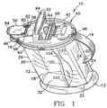
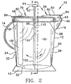
- a stirring pitcher 10 according to the present invention is illustrated in a perspective view in Fig. 1, and in elevation view in Fig. 2.
- the pitcher 10 comprises a container member 12, having a base 13, a handle 14, a spout 16 and plural walls defining a container for liquid materials.
- Four such walls are preferred.
- these comprise longitudinal walls 18, a spout wall 20 and a handle wall 22.
- the pitcher 12 container is shown having somewhat rounded sides which flare outwardly to a small degree (as viewed best in the cross-sectional view of Fig. 3).
- the upper rim of the pitcher is also in the shape of an oval at the top.
- the sides may be vertical, and the container upper rim may be in the shape of a lengthened quadrilateral such as a rectangle or even a square, as long as the sweep of the stirring or mixing assembly can reach the corners of the bottom of the container 12, as is described below.
- Another alternative configuration may include a rounded bottom and rounded end walls so that the shape of the container may resemble a truncated toroidal volume.
- the container 12 preferably defines a container volume having the attributes of both a rectangular box, including vertical corners 24,26, and an oval cylindrical top or upper container rim 30 (Fig. 3).
- the shape of container 12 resembles an inverted frusto-conical volume which at the top has a much larger oval area, when taken cross-sectionally along a horizontal plane, than when a cross-section is taken at a lower point on the container body.
- a flange or lip 28 Around the periphery of the top of all walls 18,20,22, almost to the upper rim 30, is a flange or lip 28.
- the flange 28 can provide a rib for strengthening the container shape and also provides a stop for the cover assembly when it is joined to the container 12.
- the inside surfaces of the container 12 essentially follow the outside surfaces except that the base 13 is open toward the bottom.
- the bottom inner surface 32 or floor of the container 12 is preferably straight in the lateral direction but sweeps a circular arc in the longitudinal direction, as best seen in Fig. 2. As described above, however, alternatively the bottom surface may be curved in the lateral direction (not shown).
- the locus of the arc for bottom surface 32 is approximately at the upper rim and the radius is approximately the depth or height dimension of the container 12.
- the container 12 further comprises a spout 16 on spout wall 20 at the intersection with upper rim 30.
- Spout 16 protrudes outwardly from spout wall 20, to permit easy pourability of liquids from the container 12.
- Handle 14, disposed on handle wall 22, can take any number of forms consistent with providing easy handling of the stirring pitcher assembly 10. For example, it is preferable that the handle 14 be large enough to comfortably receive the fingers of most hands.
- the handle 14 should be disposed on the surface of handle wall 22 closer to the rim 30 than to the base 13.
- Cover assembly 40 Attached to the container 12 along upper rim 30 is a cover assembly 40, which has an attachment mechanism that sealingly attaches the cover assembly 40 to the rim 30 so that fluid leakage out of the container 12 is prevented from other than through the spout 16.
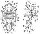
- Cover assembly 40 comprises a cover 42, having a downwardly extending rim wall 43 and including a snap groove 45 (Fig. 6). Rim wall 43 preferably describes an oval shape around the edge of cover 42, but other shapes (not shown) are also possible.
- the cover 42 includes at least two apertures, a handle aperture 44 and a spout aperture 46.
- a third aperture, a cooling stick aperture, 48 is disposed in the cover 42.
- each of the apertures 44, 46 and 48 includes a means for receiving elements which, at least to some extent, block the apertures to maintain a seal for each of the apertures, as will be explained below.
- the cover assembly 40 includes a spout closure member 50 for covering and sealingly enclosing the spout aperture 46.
- Spout closure member 50 includes downwardly disposed walls 52, (Fig. 6) which sealingly attach to corresponding walls 54 extending upwardly from the cover 42, and also include a cantilevered spout closure attachment 56 which attaches to the cover assembly 40 at a pivot point 58 disposed toward the central portion of cover assembly 40 between spout 16 and the handle aperture 44.
- the spout closure attachment 56 may take any number of forms, including a molded unitary connection of the spout closure attachment, such as a strap (not shown) attached directly to cover 40. More preferably, and as shown in Figs. 1 and 6, the spout closure attachment 56 further comprises a conventional cantilevered pivotable attachment strap 60 having a pivot pin 62 attached at the pivot retainer or mount 58.
- a spout opening tab 64 preferably being integral with the spout closure member 50, provides an extension handle for removing and replacing the spout closure member in the direction of the arrows 56 from the spout aperture 46.
- the stirrer aperture 44 is attached to cover 42 to a plurality of pivot mounts 66, about which the stirring handle and spoon combination can rotate.
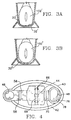
- the pivot mounts 66 provide a rounded trough 68, (Fig. 4), for receiving the stirring handle/stirring spoon subassembly, as is described below.
- the optional cooling stick aperture 48 provides the capability of performing multiple functions.
- the cooling stick aperture is structurally similar to the spout aperture 46, that is, it also comprises an upwardly extending cover wall 74.
- aperture 48 is in the shape of an oval, rather than circular, like spout aperture 46.
- a cooling stick closure member 70 (Fig. 6) includes a downwardly extending closure member wall 72 which is shaped and dimensioned to sealingly fit by interference fit within the oval cover wall 74 so as to provide an airtight closure over cooling stick aperture 48.
- Pivot pin retainers 75 (Figs. 4 and 5) are disposed between the cooling stick aperture 48 and the stirring assembly aperture 44, for mounting the closure member 70.
- the cooling stick aperture 48 has one additional feature, most clearly seen in the cross-sectional view of cover assembly 40 in Fig. 6, which preferably is not included the spout aperture 42.
- cover wall 74 Immediately below the cover wall 74 is an inwardly extending flanged lip 76 which includes secondary downwardly extending lip walls 78.
- the lip 76 provides a mount for the optional cooling stick feature, described below.
- the optional cooling stick aperture 48 may also be used to provide access to the volume within container 12.
- a closure member attachment 79 such as a strap 80, includes a pivot shaft 82 on one end, which can snap into the pivot retainers 75. The other end of strap 80 is attached to the closure member 70.
- An extending tab 84 provides an easy to operate handle for opening and closing the cooling stick aperture 48.
- Pivoting of the closure member 70 about the pivot shaft 82 within pivot retainers 75 will insert the closure member 70 into the cooling stick aperture 48, so that walls 72 and 74 will, through an interference fit, provide a seal. Pivoting the closure member 70 in the opposite direction permits opening of the cooling stick aperture and provides access for insertion of the cooling stick, described below, or for depositing therethrough solids or liquids to be mixed within the container 12.
- the oval shape of aperture 48 is significantly larger than that of the spout aperture 46 in order to provide readier access to the container 12 for pouring in liquids or depositing solids or powder therein.
- the stirring handle/spoon assembly 90 is fully illustrated in Figs. 1, 2, 3 and in a blown-up view in Fig.7.
- the subassembly of Fig. 7 illustrates and provides the best view for a description of the quick assembly feature of the assembly 90, which provides one unique feature of this invention.
- the assembly 90 comprises a handle 92 having an optional grip 94, a transverse pivot pin 96 and an insertion post 98, having a post channel 99.
- the assembly 90 further comprises a stirring spoon portion 100, which preferably includes a spoon end 102, a central spoon shaft 104 and an insertion end 106, including a channel 108 for receiving the handle insertion post 98.
- a stirring spoon portion 100 which preferably includes a spoon end 102, a central spoon shaft 104 and an insertion end 106, including a channel 108 for receiving the handle insertion post 98.
- one or more retaining or tightening bands 110 provide a more durable interference fit between the post and the channel 108.
- the channel 108 may include one or more channel inserts 112, which cooperate with the corresponding post channel 99 of similar shape extending longitudinally along the post 98, so as to further increase the retention capability of the channel 108 to hold post 98 by interference fit.
- the post 98 will be inserted and removed from channel 108 numerous times during long term use of the pitcher 10 for purposes of cleaning.
- the more durable the connection between the post 98 and shaft channel 108 the longer the assembly 90 can be utilized for its intended purpose.
- the construction of the post 98 and channel 108 provides a convenient and simple connection between the handle 94 and spoon shaft 104, so that a second installation of the assembly 90 within the pitcher 10 is facilitated.
- the handle/spoon assembly 90 is preferably capable of multiple disassembly and reassembly operations.
- the handle 92 extends above the cover assembly 40 and the stirring spoon is disposed below the cover 40 within the container 12, as shown in Figs. 1-3.
- the post 98 extends through the stirrer aperture 44, and the transverse stirrer pivot pin 96 snaps into place between the pivot mounts 66 adjacent aperture 46.
- the structure of the pivot mounts 66 provides a retention capability to retain the stirrer pivot pin 96 releasably attached to the cover 44.
- the pivot pin 96 itself rotates within the transverse rounded channel or trough 68, which has an opposed mating structure that matches the structure of the pivot pin 96.
- stirrer assembly 90 is disposed on either side of cover 42 and is pivotable about the shaft pivot 96 in the direction shown by the arrows (Fig. 2). Pivoting rotational motion of the handle 92, of course, causes the stirring spoon 100 to describe an arc within the container 12 in the opposite direction.
- aperture 44 provides for a cover which allows only a minimum amount of air to circulate within the container 12, and almost no fluid leakage from pitcher 10, even if the pitcher 10 ends up on its side.
- the fluid-tight sealing of the spout aperture 46 and of the cooling stick aperture 48 is described above.
- the structure of pivot pin 96 and the handle post 98 within the pivot mounts 66 within the trough to a great extent closes off any openings for fluid circulation.
- assembly of the spoon/handle subassembly first requires insertion of the handle post 98 through stirrer aperture 44 and engaging the pivot pin 96 within the pivot mounts 66.
- the handle 92 may pivot about the pin 96, in the direction of the arrows as shown (Fig. 2).
- the spoon shaft 104 may then be brought up from below cover 42 and the shaft post 98 is inserted into channel 108 until the end of post 98 meets the end of channel 108.
- sufficient clearance is provided between the end of insertion end 106 and the underside of the cover 42 to permit the spoon/handle assembly 90 to pivot about pin 96.
- the cover subassembly 40 is then snapped into place around rim 30, making sure that rim 30 provides a snug interference fit within the snap groove 45 all around the rim 30.
- the shape of rim 30 and of the corresponding snap groove 45 coact to provide a fluid-tight seal between the rim wall 43 and the rim 30 of container 12.
- the spoon end 102 of the stirrer is free to rotate around the container 12 within the sidewalls 18. If the stirring pitcher has been correctly assembled, the spoon end 102 is disposed along the bottom wall 32 of container 12, leaving a slight clearance between them. Thus, the spoon end 102 is free to describe an arc which follows the contour of the arc of bottom wall 32 from one end wall 20 to the other end wall 22. Moreover, as is clearly seen in the cross-sectional view of Fig. 3, there is also a slight clearance between the spoon end 102 and the sidewalls 18, especially at the distal end of the spoon 100. The facing outline or contour of the spoon end follows the contour of the junction of walls 18 with the bottom wall 32 along the complete arc described by bottom wall 32.
- FIG. 3A an ovoid container bottom wall 32' having rounded corners 33' is matched by a spoon end 102' which is also ovoid in shape.
- Fig. 3B circular spoon end 102'' follows exactly the contour of a circular container bottom wall 32".
- an optional cooling stick 120 is shown inserted into the cooling stick aperture 48 and extends into the container 12.
- the cooling stick comprises a separate container insert 122 which is intended to hold ice cubes or other frozen, freezable or cool material.
- the material is preferably kept separate from the liquid contained within the pitcher container.
- the frozen or freezable material may comprise any of the following or similar materials known to the industry: ice, ice cubes, blue ice, THERMAL CERAMICS, or a thermofor.
- the shape of the separate container insert 122 is an elongated tube which has an oval cross-section matching the oval shape of the cooling stick aperture 48.
- the length of tubular insert 122 should not exceed the length of the wall 20 of the container 12, so that inserting the tubular insert into the aperture 48 of cover 47 will cause insert 122 to fit within the container 12 without protruding above the cover 42.
- a stopper 126 may be used to enclose or sealingly cover opening 124.
- the stopper 126 includes a protruding handle portion 128 which extends away from the container 122 and which can be used as a handle for removing the stopper 126 from the container insert 122.
- a flange 130 extends laterally beyond the edges of opening 124 to hold the tubular insert 170 within the aperture 48.
- container walls 18, 20 and 22 is a clear plastic material which is transparent.
- the elements within container 12, e.g., cooling stick 122 and spoon end 102 are drawn in solid lines, rather than broken lines, to indicate the element which is identified.
- cover 42 is opaque and the elements behind the downwardly extending cover wall 43 are not shown.
- the cooling stick aperture 48 includes a downwardly extending cover wall 74, which preferably has a length somewhat greater than the height of stopper 126, including the handle portion 128.
- the lateral dimensions of the cover wall 74 exceed slightly the dimensions of the flange 130, so as to accommodate insertion of the stopper 126 within the volume enclosed by the cover wall 74.
- flanged lip 76 of the aperture 48 does not extend inwardly of the cover wall 74 to such a degree as to interfere with the insertion of the tubular container insert 122 within the aperture; rather, the dimensions of flanged lip 76 and of downwardly extending lip walls 78 are such as to snugly fit over the tubular walls of container insert 122 so as to retain the container insert within the aperture opening.
- the flanged lip 76 acts also to stop the full insertion of the container insert 120 into aperture 48 without a means to retain the container insert 120 in place.
- the flanged lip 76 has a dimension which prevents the stopper flange 130, and thus the stopper 126 and insert container 122, from falling into the container 12.
- the cooling stick can provide cooling of the contents in container 12, either through ice contained within container insert 120 or other conventional cooling chemicals.
- such chemicals are known and available from the assignee hereof, Sierra Housewares, Inc. of Chicago, Illinois.
- the cooling stick is especially convenient when it is not desirable for water to melt from ice and to dilute the contained liquid.
- a mixed cocktail may have a predetermined recipe, and it is desired that the liquid melting from ice not dilute the drink mixture.
- the container insert 122 of cooling stick 120 contains and keeps isolated melting ice water or chemicals. Refreezing the water or chemicals after use in the stirring pitcher 10 permits the reuse of the cooling stick 120 in pitcher 10 subsequent to cleaning out the pitcher container 12 and of the stirrer subassembly 90.
- bottom wall 32 is shown extending as an arc in one direction (Fig. 2) and as a straight surface in the lateral direction, as shown in Fig. 3.
- the shape of that surface in the lateral direction may take any of a number of different shapes, for example, a curved or oval surface (not shown), and this will be sufficient to utilize the teachings of this invention as long as the corresponding contour of the spoon end has identical or essentially similar shape or contour to that of the bottom wall.
Landscapes
- Chemical & Material Sciences (AREA)
- Chemical Kinetics & Catalysis (AREA)
- Table Devices Or Equipment (AREA)
- Accessories For Mixers (AREA)
- Mixers Of The Rotary Stirring Type (AREA)
- Food-Manufacturing Devices (AREA)
Claims (18)
- Rührkrug (10), der folgendes umfasst:a) einen Behälter (12) mit einer nach oben zeigenden Behälteröffnung;b) eine Behälterabdeckung (42) zum Abdecken der nach oben zeigenden Behälteröffnung, wobei die genannte Behälterabdeckung (42) über der genannten Behälteröffnung entfernbar und austauschbar ist, um die genannte Behälteröffnung zu öffnen und zu schließen, wobei die genannte Behälterabdeckung (42) ferner mindestens eine Angelfassung (66), eine erste Arbeitsöffnung (44) und eine zweite Gießöffnung (46) aufweist; undc) einen schwenkbaren Rührer (100), der sich durch die genannte erste Arbeitsöffnung (44) der genannten Behälterabdeckung erstrecken kann, wobei der genannte Rührer (100) ein Löffelende (102), einen zentralen Schaft (104), der sich von dem genannten Löffelende (102) entlang einer Längsachse erstreckt, und ein Rührerhandstück-Befestigungsende (106), das entgegengesetzt zu dem genannten Löffelende (102) angeordnet ist, aufweist, und wobei der genannte zentrale Schaft (104) einen Drehzapfen (96) aufweist, der quer zu der Längsachse des Schaftes angeordnet ist, wobei der genannte Rührer (100) an der genannten ersten Arbeitsöffnung (44) an der genannten Abdeckung (42) angebracht werden kann, so dass der genannte Drehzapfen (96) mit der genannten Angelfassung (66) an der genannten Abdeckung (42) eingreift, was bewirkt, dass sich das genannte Handstück-Befestigungsende (106) des genannten Rührers (100) außerhalb der genannten Abdeckung (42) erstreckt, und dass sich das genannte Löffelende (102) des genannten Rührers (100) in dem genannten Behälter (12) erstreckt, wenn die genannte Behälterabdeckung (42) mit dem genannten Behälter (12) eingreift, um die genannte Behälteröffnung abzudecken.
- Rührkrug (10) nach Anspruch 1, wobei der genannte Behälter (12) ferner eine Form mit mindestens zwei Seitenwänden (18) und einer unteren Wand (32) aufweist, wobei der genannte Behälter (12) einem lang gestreckten Trog ähnlich ist, wobei die genannten unteren und Seitenwände (18, 32) des Behälters eine Querschnittsform aufweisen, die eine Kontur begrenzt, die im Wesentlichen mit der Kontur zumindest des unteren Abschnitts des genannten Löffelendes (102) identisch ist, und die genannte untere (32) Wand des genannten Behälters (12) einen Bogen mit einem Radius definiert, dessen geometrischer Ort ungefähr an dem Drehzapfenende (96) des genannten Rührerschafts (104) angeordnet ist.
- 'Rührkrug (10) nach einem der Ansprüche 1 oder 2, wobei die genannte Abdeckung (42) ferner eine dritte Arbeitsöffnung (48) aufweist, die angrenzend an ein laterales Ende der genannten Behälterseitenwände (18) angeordnet ist, wobei der genannte Behälter (12) ferner ein entfernbares und austauschbares Verschlusselement (70) für die genannte dritte Arbeitsöffnung (48) aufweist, wobei das genannte Verschlusselement (70) an der genannten Abdeckung (42) angebracht werden kann.
- Rührkrug (10) nach einem der Ansprüche 1 bis 3, wobei der genannte Rührer eine Rührteileinheit definiert, die folgendes umfasst:a) ein Handstück (92), welches das genannte Rührerhandstück-Befestigungsende (106) aufweist, wobei sich der genannte transversal ausgerichtet Drehzapfen (96) und ein Einführungsstift (98) von dem genannten Handstück (92) weggehend erstrecken; undb) einen lösbaren Rührlöffelabschnitt, der einen zentralen Löffelschaft (104) und ein Löffelende (102) aufweist, das an dem genannten zentralen Löffelschaft angebracht ist, wobei der genannte zentrale Löffelschaft einen Einführungskanal (108) an einem Ende aufweist, das entgegengesetzt zu dem genannten Löffelende (102) angeordnet ist, das so geformt, bemessen und ausgerichtet ist, dass es den genannten Handstückeinführungsstift (108) empfängt, wobei die Einführung des genannten Einführungsstifts (108) durch die genannte erste Arbeitsöffnung (44) und in den genannten Löffelabschnitt-Einführungskanal einen Eingriff des genannten Rührerhandstück-Befestigungsendes (106) mit dem genannten Löffelabschnitt bewirkt, so dass eine Drehbewegung des Rührerhandstücks um den genannten Drehzahpfen (96) bewirkt, dass sich das genannte Löffelende (102) in die entgegengesetzte Richtung um den genannten Drehzapfen (96) dreht.
- Rührkrug (10) nach einem der Ansprüche 2 bis 4, wobei die genannte untere Wand (32) des genannten Behälters (12) einen Bogen mit einem Radius vorsieht, der ungefähr der Strecke von dem genannten Rührerdrehzapfen (96) zu dem distalen Ende des genannten Löffelendes (102) entspricht, und wobei der durch die genannte untere Wand (32) und die Seitenwände (18) definierte Behälterboden eine Kontur aufweist, die im Wesentlichen mit der Kontur des genannten Löffels identisch ist, und wobei eine Rotation des genannten Handstücks (92) um den genannten Drehzapfen (96) bewirkt, dass das genannte distale Ende des genannten Rührlöffelendes (102) einen Bogen vorsieht, der dem Bogen der genannten unteren Wand folgt.
- Rührkrug (10) nach Anspruch 5, wobei die Kontur des genannten Löffelendes (102) und des genannten Behälterbodens rechteckig ist.
- Rührkrug (10) nach Anspruch 5, wobei die Kontur des genannten Löffelendes (102) und des genannten Behälterbodens oval ist.
- Rührkrug (10) nach Anspruch 5, wobei die Kontur des genannten Löffelendes (102) und des genannten Behälterbodens rund ist.
- Rührkrug (10) nach Anspruch 4, wobei das genannte Handstück (92) ferner einen lösbaren Handstückgriff (94) aufweist, der ein distales Ende des genannten Handstück-Befestigungsendes (106) entfernt von dem genannten Drehzapfen (96) abdeckt.
- Rührkrug (10) nach einem der Ansprüche 3 bis 9, wobei die genannte zweite Arbeitsöffnung (96) der Behälterabdeckungseinheit eine verschlossene Gießöffnung darstellt, und wobei die genannte dritte Arbeitsöffnung (48) eine verschließbare Kühlstaböffnung darstellt.
- Rührkrug (10) nach Anspruch 10, wobei die genannte Behälterabdeckungseinheit (40) ferner ein Verschlusselement (76) zum dichten Verschließen der genannten Gießöffnung (46) umfasst.
- Rührkrug (10) nach Anspruch 11, wobei die genannte Kühlstaböffnung (48) eine ovale Form aufweist, wobei das genannte Verschlusselement (70) ein ovales Ende zum Einführen in die genannte Kühlstaböffnung (48) aufweist.
- Rührkrug (10) nach Anspruch 12, wobei die genannten Verschlusselemente (50, 70) für die genannten Gieß- und Kühlstaböffnungen (46, 48) jeweils einen Drehpunkt (62, 82) für einen Eingriff mit separaten Angelfassungen (58, 75) an der genannten Behälterabdeckung (12) aufweisen, wobei es die genannten Drehpunkte (62, 82) ermöglichen, dass die genannten Verschlusselemente (50, 70) um die genannten Angelfassungen (58, 75) schwenken.
- Rührkrug (10) nach Anspruch 12, wobei dieser ferner ein Kühlelement (120) umfasst, das in den genannten Krugbehälter (12) eingeführt werden kann, wobei das genannte Kühlelement (120) einen verschließbaren Hohlraum zur Aufnahme eines Kühlmittels aufweist sowie ein Einfassungselement (126) zum Umschließen des Kühlelements, so dass der Kühlelementhohlraum von dem genannten Krugbehälter (10) isoliert wird, wenn das genannte Kühlelement (120) in den genannten Krugbehälter (12) eingeführt wird.
- Rührkrug (10) nach Anspruch 14, wobei die genannte Kühlstaböffnung (48) ferner eine verengende Seitenwand (78) aufweist, um das genannte einführbare Kühlelement (120) nah an der genannten Kühlstaböffnung (48) zu halten, wobei die genannte Kühlstaböffnung (48) und das genannte Kühlelement (120) so geformt und bemessen sind, dass sie es ermöglichen, dass das genannte Kühlstaböffnungsverschlusselement (70) die genannte Kühlstaböffnung (48) verschließt, nachdem das genannte Kühlelement (120) in die genannte Kühlstaböffnung (48) eingeführt worden ist.
- Kühlkrug (10) nach Anspruch 14, wobei das genannte Kühlmittel ferner Eis umfasst.
- Kühlkrug (10) nach Anspruch 14, wobei das genannte Kühlmittel ferner eine gefrierfähige chemische Zusammensetzung umfasst.
- Rührkrug (10) nach Anspruch 17, wobei die genannte gefrierfähig chemische Zusammensetzung ferner blaues Eis, thermische Keramikwerkstoffe oder ein Thermofor umfasst.
Applications Claiming Priority (2)
| Application Number | Priority Date | Filing Date | Title |
|---|---|---|---|
| US09/354,678 US6086240A (en) | 1999-07-16 | 1999-07-16 | Stirring Pitcher having pivotable stirring handle |
| US354678 | 1999-07-16 |
Publications (2)
| Publication Number | Publication Date |
|---|---|
| EP1068894A1 EP1068894A1 (de) | 2001-01-17 |
| EP1068894B1 true EP1068894B1 (de) | 2004-11-10 |
Family
ID=23394454
Family Applications (1)
| Application Number | Title | Priority Date | Filing Date |
|---|---|---|---|
| EP00304137A Expired - Lifetime EP1068894B1 (de) | 1999-07-16 | 2000-05-17 | Rührkrug mit schwenkbarem Rührhandgriff |
Country Status (4)
| Country | Link |
|---|---|
| US (2) | US6086240A (de) |
| EP (1) | EP1068894B1 (de) |
| CA (1) | CA2313437C (de) |
| DE (1) | DE60015660T2 (de) |
Families Citing this family (38)
| Publication number | Priority date | Publication date | Assignee | Title |
|---|---|---|---|---|
| US6283627B1 (en) | 2000-09-12 | 2001-09-04 | Wayne G. Fromm | Drink mixer |
| AU2002309886B2 (en) * | 2001-05-18 | 2006-03-02 | Chemineer, Inc. | Mixing arrangement for tanks |
| CA2376628C (en) * | 2002-03-19 | 2004-06-22 | Leonard L. Simba | Drinking vessel stirrer |
| CA2439073A1 (en) * | 2002-09-03 | 2004-03-03 | George A.S. Kitson | Container stirring mechanism |
| US7293427B1 (en) * | 2004-08-17 | 2007-11-13 | Cushnie Pamela F | Beverage cooling apparatus and method |
| USD530617S1 (en) * | 2004-11-18 | 2006-10-24 | Plastipak Packaging, Inc. | Container |
| US20060263490A1 (en) * | 2005-05-19 | 2006-11-23 | Eric Wall | Frozen confectionery maker |
| US7946752B2 (en) * | 2005-09-06 | 2011-05-24 | Sharron Swartz | Mug with stirring mechanism |
| US7644829B2 (en) * | 2006-08-07 | 2010-01-12 | Plastipak Packaging, Inc. | Plastic container including a grip feature |
| ITBO20060888A1 (it) * | 2006-12-28 | 2008-06-29 | Ali Spa | Agitatore a perdere per prodotti alimentari miscelati. |
| US8430557B2 (en) * | 2007-03-13 | 2013-04-30 | Vita-Mix Corporation | Spoon food mixer |
| WO2009009771A1 (en) * | 2007-07-12 | 2009-01-15 | Oldenburg Kevin R | Disposable spinner flask |
| US8099965B2 (en) * | 2008-10-13 | 2012-01-24 | John Stelmach | Cold probe for cooling liquids |
| US20100208549A1 (en) * | 2008-12-08 | 2010-08-19 | Kitson George A S | Pitcher Lid with Spout Gate and Stirring Mechanism |
| US20100275785A1 (en) * | 2009-04-29 | 2010-11-04 | Michael Weissman | Automatic french press |
| US20100294135A1 (en) * | 2009-05-22 | 2010-11-25 | Michael Weissman | Automatic French Press |
| CH702957A1 (de) * | 2010-04-08 | 2011-10-14 | Pi Design Ag | Getränkebereiter mit blockierbarer Betätigungsstange. |
| US9192264B2 (en) | 2010-07-27 | 2015-11-24 | Euro-Pro Operating Llc | Food processor |
| US8721164B2 (en) | 2010-07-27 | 2014-05-13 | Euro-Pro Operating Llc | Food processor with attachment |
| JP5474182B2 (ja) * | 2011-02-09 | 2014-04-16 | 三菱レイヨン株式会社 | 浄水カートリッジおよびピッチャー型浄水器 |
| US9109316B1 (en) | 2011-07-06 | 2015-08-18 | John William Thomson | Portable washing apparatus |
| GB201208159D0 (en) * | 2012-05-08 | 2012-06-20 | Dkb Household Uk Ltd | Liquid condiment dispensers |
| US20140332478A1 (en) | 2012-05-13 | 2014-11-13 | Aquasana, Inc. | Pitchers, filtration units, and filtration systems and methods |
| US20150201807A1 (en) * | 2012-09-03 | 2015-07-23 | Koninklijke Philips N.V. | Beaker for a blender equipped with a blender bar |
| BR112015004221A2 (pt) * | 2012-10-05 | 2017-07-04 | Koninklijke Philips Nv | jarra para o preparo de bebidas; e sistema |
| USD867828S1 (en) * | 2014-12-10 | 2019-11-26 | Leah Ceee O. Boomsma | Pouch holder |
| US10377559B1 (en) | 2013-12-10 | 2019-08-13 | Leah Ceee O. Boomsma | Holder for a squeeze pouch |
| US11465821B1 (en) | 2013-12-10 | 2022-10-11 | LCeeeDesigns LLC | Holder for food and beverage containers |
| USD966040S1 (en) * | 2013-12-10 | 2022-10-11 | LCeeeDesigns LLC | Pouch holder |
| US20150259218A1 (en) * | 2014-03-14 | 2015-09-17 | Aquasana, Inc. | Filtration units, filtration systems, and filtration methods |
| GB201505471D0 (en) * | 2015-03-30 | 2015-05-13 | Akasha Nabil S K | Lid for beverage containers |
| USD790900S1 (en) | 2016-01-08 | 2017-07-04 | Tervis Tumbler Company | Pitcher with carrying handle |
| US10363527B2 (en) * | 2016-09-30 | 2019-07-30 | Munchkin, Inc. | Mixing container |
| CN109808126B (zh) * | 2017-11-21 | 2024-05-28 | 广东美的生活电器制造有限公司 | 芯件、搅拌器、泡奶机以及搅拌器的制作方法 |
| CN110269473B (zh) * | 2019-04-24 | 2021-04-23 | 祁爱军 | 一种简单清洗水杯 |
| AU2020287070B2 (en) * | 2019-06-05 | 2026-03-19 | Breville Pty Limited | A lid for a food processor |
| WO2021234052A1 (en) * | 2020-05-19 | 2021-11-25 | De'longhi Braun Household Gmbh | Spatula |
| US20230084609A1 (en) * | 2021-09-13 | 2023-03-16 | Sandra Washington | Logo Drinkware and Serving Tray Set |
Family Cites Families (27)
| Publication number | Priority date | Publication date | Assignee | Title |
|---|---|---|---|---|
| US477063A (en) * | 1892-06-14 | Churn | ||
| US135761A (en) * | 1873-02-11 | Improvement in churns | ||
| US2993A (en) * | 1843-03-10 | lindley | ||
| US437331A (en) * | 1890-09-30 | Churn | ||
| US383938A (en) * | 1888-06-05 | Bread-machine | ||
| US681386A (en) * | 1900-09-10 | 1901-08-27 | Gomer G Beynon | Churn. |
| US1548614A (en) * | 1924-10-01 | 1925-08-04 | Joseph H Konigsberg | Metal-stirring device |
| US1948431A (en) * | 1932-07-26 | 1934-02-20 | Rolph William Mair | Mixing device |
| US1995998A (en) * | 1934-06-26 | 1935-03-26 | Nefedov Basil | Clothes washing machine |
| US2559196A (en) * | 1950-07-12 | 1951-07-03 | Nicholas J Medved | Time saver frying pan lid |
| US3417972A (en) * | 1968-01-31 | 1968-12-24 | Hoover Co | Blender jar with stirrer and strainer |
| US4010934A (en) * | 1976-03-17 | 1977-03-08 | Mccord King S | Liquid mixing and dispensing device |
| US4197018A (en) * | 1979-01-08 | 1980-04-08 | Groen Division - Dover Corporation | Mixer |
| US4460279A (en) * | 1982-08-25 | 1984-07-17 | Krasney Robert L | Liquid pitcher with mixer |
| US4946287A (en) * | 1986-08-14 | 1990-08-07 | Vita-Mix Corporation | Agitator for a food mixer and method of use thereof |
| US4893940A (en) * | 1987-03-09 | 1990-01-16 | Waisberg Stephen L | Stirrer device for a beverage pitcher, and beverage pitcher incorporating such a stirrer device |
| CA1280109C (en) * | 1987-07-08 | 1991-02-12 | Laszlo Murzsa | Paint mixing container |
| US4946286A (en) * | 1988-11-23 | 1990-08-07 | The Coca-Cola Company | Liquid pitcher including a mixing and grinding mechanism |
| DE3923928A1 (de) * | 1989-07-19 | 1991-01-24 | Werner Prof Dr Ing Stahl | Bioreaktor |
| US5112135A (en) * | 1990-06-25 | 1992-05-12 | Rupp Carl A | Mixer |
| US5407270A (en) * | 1992-03-17 | 1995-04-18 | Barile; Miriam | Stirring pitcher |
| US5425579A (en) * | 1994-08-15 | 1995-06-20 | Sampson; Edwin J. | Beverage pitcher with agitator |
| US5472274A (en) * | 1994-09-12 | 1995-12-05 | Baillie; Rosa A. | Pitcher with cooling and stirring structures |
| US5476321A (en) * | 1995-04-05 | 1995-12-19 | Mcnaughton; Betty | Container stirring device |
| US5695282A (en) * | 1996-02-23 | 1997-12-09 | The Pampered Chef, Ltd. | Mixing pitcher |
| US5943947A (en) * | 1997-01-22 | 1999-08-31 | 21St Century Cookware Inc. | Cooking apparatus having special ports |
| DE29816201U1 (de) * | 1998-09-09 | 2000-01-13 | Emsa-Werke Wulf GmbH & Co, 48282 Emsdetten | Mixbehälter |
-
1999
- 1999-07-16 US US09/354,678 patent/US6086240A/en not_active Expired - Fee Related
-
2000
- 2000-03-23 US US09/533,146 patent/US6210032B1/en not_active Expired - Fee Related
- 2000-05-17 EP EP00304137A patent/EP1068894B1/de not_active Expired - Lifetime
- 2000-05-17 DE DE60015660T patent/DE60015660T2/de not_active Expired - Fee Related
- 2000-07-06 CA CA002313437A patent/CA2313437C/en not_active Expired - Fee Related
Also Published As
| Publication number | Publication date |
|---|---|
| CA2313437C (en) | 2007-01-16 |
| EP1068894A1 (de) | 2001-01-17 |
| CA2313437A1 (en) | 2001-01-16 |
| US6086240A (en) | 2000-07-11 |
| US6210032B1 (en) | 2001-04-03 |
| DE60015660T2 (de) | 2005-12-01 |
| DE60015660D1 (de) | 2004-12-16 |
Similar Documents
| Publication | Publication Date | Title |
|---|---|---|
| US6086240A (en) | Stirring Pitcher having pivotable stirring handle | |
| US7040799B2 (en) | Stirring stick | |
| US7217028B2 (en) | Off-axis goblet for food mixer | |
| US8136978B2 (en) | Tumbler with stirring assembly | |
| CN113825434B (zh) | 搅拌设备和方法 | |
| US10994901B2 (en) | Cap for a drinking vessel | |
| CN100502745C (zh) | 分配搅拌器 | |
| US6264068B1 (en) | One-handed container for dispensing a solid and a liquid | |
| CA2465482C (en) | Beverage mixer | |
| EP2955127B1 (de) | Behälter mit tropfsicherer kappe | |
| US4022344A (en) | Attachment for a liquid container | |
| US5284389A (en) | Juice concentrate mixing and dispensing apparatus | |
| CA2519661A1 (en) | Mixer with optional faucet | |
| CA3136972A1 (en) | Blending apparatus and methods | |
| JP2024149322A (ja) | 容器の蓋 | |
| US20050105387A1 (en) | Drink bottle with integrated mixing blades | |
| CN110392540A (zh) | 搅拌设备和方法 | |
| JP2001120414A (ja) | マドラー | |
| US20080277424A1 (en) | Flip-top shaker | |
| CN121220581A (zh) | 用于实现冷烹饪制备物的烹饪制备设备 | |
| JP2001043439A (ja) | 飲料ディスペンサ | |
| US20050207271A1 (en) | Twisted stir-stick for food mixer | |
| CN121220580A (zh) | 用于冷烹饪制备物的烹饪加工工具 | |
| CN117881469A (zh) | 不对称搅拌器杯子和马达底座啜吸机构 | |
| JPS6287055A (ja) | 家庭用ソフトアイスクリ−ム製造器 |
Legal Events
| Date | Code | Title | Description |
|---|---|---|---|
| PUAI | Public reference made under article 153(3) epc to a published international application that has entered the european phase |
Free format text: ORIGINAL CODE: 0009012 |
|
| AK | Designated contracting states |
Kind code of ref document: A1 Designated state(s): DE ES FR GB NL |
|
| AX | Request for extension of the european patent |
Free format text: AL;LT;LV;MK;RO;SI |
|
| 17P | Request for examination filed |
Effective date: 20010704 |
|
| AKX | Designation fees paid |
Free format text: DE ES FR GB NL |
|
| 17Q | First examination report despatched |
Effective date: 20021218 |
|
| GRAP | Despatch of communication of intention to grant a patent |
Free format text: ORIGINAL CODE: EPIDOSNIGR1 |
|
| GRAS | Grant fee paid |
Free format text: ORIGINAL CODE: EPIDOSNIGR3 |
|
| GRAA | (expected) grant |
Free format text: ORIGINAL CODE: 0009210 |
|
| AK | Designated contracting states |
Kind code of ref document: B1 Designated state(s): DE ES FR GB NL |
|
| PG25 | Lapsed in a contracting state [announced via postgrant information from national office to epo] |
Ref country code: FR Free format text: LAPSE BECAUSE OF NON-PAYMENT OF DUE FEES Effective date: 20041110 Ref country code: NL Free format text: LAPSE BECAUSE OF FAILURE TO SUBMIT A TRANSLATION OF THE DESCRIPTION OR TO PAY THE FEE WITHIN THE PRESCRIBED TIME-LIMIT Effective date: 20041110 |
|
| REG | Reference to a national code |
Ref country code: GB Ref legal event code: FG4D |
|
| REF | Corresponds to: |
Ref document number: 60015660 Country of ref document: DE Date of ref document: 20041216 Kind code of ref document: P |
|
| PG25 | Lapsed in a contracting state [announced via postgrant information from national office to epo] |
Ref country code: ES Free format text: LAPSE BECAUSE OF FAILURE TO SUBMIT A TRANSLATION OF THE DESCRIPTION OR TO PAY THE FEE WITHIN THE PRESCRIBED TIME-LIMIT Effective date: 20050221 |
|
| NLV1 | Nl: lapsed or annulled due to failure to fulfill the requirements of art. 29p and 29m of the patents act | ||
| PLBE | No opposition filed within time limit |
Free format text: ORIGINAL CODE: 0009261 |
|
| STAA | Information on the status of an ep patent application or granted ep patent |
Free format text: STATUS: NO OPPOSITION FILED WITHIN TIME LIMIT |
|
| 26N | No opposition filed |
Effective date: 20050811 |
|
| EN | Fr: translation not filed | ||
| EN | Fr: translation not filed | ||
| PGFP | Annual fee paid to national office [announced via postgrant information from national office to epo] |
Ref country code: DE Payment date: 20080630 Year of fee payment: 9 |
|
| PGFP | Annual fee paid to national office [announced via postgrant information from national office to epo] |
Ref country code: GB Payment date: 20080529 Year of fee payment: 9 |
|
| GBPC | Gb: european patent ceased through non-payment of renewal fee |
Effective date: 20090517 |
|
| PG25 | Lapsed in a contracting state [announced via postgrant information from national office to epo] |
Ref country code: GB Free format text: LAPSE BECAUSE OF NON-PAYMENT OF DUE FEES Effective date: 20090517 |
|
| PG25 | Lapsed in a contracting state [announced via postgrant information from national office to epo] |
Ref country code: DE Free format text: LAPSE BECAUSE OF NON-PAYMENT OF DUE FEES Effective date: 20091201 |