EP1069226A1 - Aiguille de machine à coudre avec formation améliorée des boucles - Google Patents
Aiguille de machine à coudre avec formation améliorée des boucles Download PDFInfo
- Publication number
- EP1069226A1 EP1069226A1 EP00106095A EP00106095A EP1069226A1 EP 1069226 A1 EP1069226 A1 EP 1069226A1 EP 00106095 A EP00106095 A EP 00106095A EP 00106095 A EP00106095 A EP 00106095A EP 1069226 A1 EP1069226 A1 EP 1069226A1
- Authority
- EP
- European Patent Office
- Prior art keywords
- needle
- eye
- thread
- tip
- needle according
- Prior art date
- Legal status (The legal status is an assumption and is not a legal conclusion. Google has not performed a legal analysis and makes no representation as to the accuracy of the status listed.)
- Granted
Links
Images


Classifications
-
- D—TEXTILES; PAPER
- D05—SEWING; EMBROIDERING; TUFTING
- D05B—SEWING
- D05B85/00—Needles
Definitions
- the invention relates to a needle, in particular for mechanical insertion of a thread into the material.
- a tufting needle for known the carpet manufacture, which serves a staple fiber yarn to pierce through a base fabric and with the To form staple yarn loops.
- the tufting needle for this purpose has an approximately cylindrical shaft which is pointed at one end. Is near the top a funnel-shaped eye is formed at an angle to the central axis of the needle.
- An air duct is provided in the tufting needle with which the eye can be pressurized with compressed air.
- the shaft is on the clamping side cylindrical and conical towards the tip. The inclination of the eye to the longitudinal axis is approximately 30 °.
- Another tufting needle is known from EP 0187925. This starts from a tubular body, which is cut obliquely to form a tip. On the opposite side of the slope is the tubular one Basic body also opened so that a through the open interior running thread at the slant arranged mouth surface of the tubular base body can leak. The eye thus formed has an oval Cross-section due to the tubular base body given deformation changes along the eye. On the open side of the tubular body opposite side is the tubular base body flattened so that an indentation or groove is formed is.
- Another tufting needle is from DE 2834738 C2 known.
- This needle has a flat needle body Cross-section based on one embodiment almost unchanged to an eye that extends across directed to the longitudinal axis of the needle and elongated oval is.
- a gutter leads to the eye, which is considerable is flatter than the thread.
- the length of the eye is at this Embodiment about the size of the mouth of the eye on the two corresponding opposite one another Needle sides.
- FIG. 5 of the patent specification is a tufting needle with an approximately spoon-shaped Head known.
- a thread groove extends along the shaft, whose depth is less than the thread thickness and essential is less than the eye width.
- the eye is oval trained and extends across the tufting needle.
- On the opposite side of the thread gutter is in Area of the eye and a subsequent shaft area a deflection is provided.
- From DE-OS 2412062 is also a sewing needle known to interact with a thread gripper is set up.
- the sewing needle serves the upper thread to pierce through the material, the forming The loop is then held and enlarged by a thread gripper becomes.
- the sewing needle has a shaft with a thread groove whose depth is slightly greater than that smallest eye diameter so that the thread is completely in the thread trough runs.
- the eye extends on one arcuate path across the needle and expanding thereby funnel-shaped.
- the ear cross-section is fixed oval.
- a trough is provided for the hook or gripper, who works with the needle.
- the needle according to the invention has a long thread well-leading eye and one adjacent to the eye exit Hump to clamp the thread in the material.
- the eye is through a preferably straight passage formed at an acute angle against the longitudinal direction of the needle is inclined. This results in a low friction of the through the eye of running thread on the eye and a good one Thread guidance.
- the thread is pulled back through the eye of the needle and thus a contraction of the needle during the puncturing process generated thread loop avoided.
- the needle according to the invention can therefore produce a loop which, when retracting the needle in its ideal full training is maintained.
- the stake a gripper that holds the sling is not required. This makes it possible to thread even thicker ones Just stab textile.
- E.g. can several Layers of material, e.g. Carbon fiber mats to be fixed. It then only one upper thread without bobbin thread is used.
- the height of the mats can be up to 40mm or more and does not have to be constant. This is the case, for example, with aircraft wings made of laminate material.
- Another advantage is the elimination of the knotting process.
- the gripper is superfluous. This will the thread is spared. Only the required amount of thread is running through the eye.
- one Lockstitch process with each loop formation longer thread lengths to pull through the eye to by means of a gripper pass the loop around a bobbin case to be able to. The hook therefore pulls a thread length through the eye, which then when tightening (knotting) the Upper thread is withdrawn again. Run this way Thread sections often in the conventional sewing process through the eye until it is finally part of the seam to the Come calm.
- the needle according to the invention allows this to be avoided such a thread load.
- the needle according to the invention can be stable be formed. It is not a groove for a gripper required. Accordingly, the otherwise existing one is dropped Cross-sectional weakening.
- the needle according to claim 2 provides the same advantages.
- the opening of the eye extends with a pointed one Angle through the needle body and thereby becomes relative long.
- the circular cross-section gives a good one Thread guide and the thread is stabilized.
- Needle for inserting thread into the material and forming loops, ideally in full training on the return stroke is preserved if the eye is in one very acute angle to the longitudinal direction of the needle is. If the input and the output of the ⁇ hrs are axially offset from each other, so that from Viewed from the side, the entrance and exit of the Do not overlap the needle (i.e. a positive one remains Axial distance between the entrance and exit of the eye) the thread is a good guide and runs with less Friction through the eye. Thus a thread take with the Needle return stroke avoided.
- the eye is preferably cylindrical, what also serves the stated purpose.
- the thread guide It is also useful to have the largest possible eye length, whereby the Length L of the eye is preferably greater than the thickness of the Needle.
- a groove on the shaft leading to the eye enables the thread guide and the almost frictionless drawing of thread into the material when the depth of the gutter approximately matches or is larger than the eye diameter than this.
- the thread channel can be a rectangular, have square or other cross-section.
- the eye is at the entrance of the thread gutter remote side preferably bounded by an edge, the (somewhat rounded and) on the outside of the needle is arranged.
- the edge serves to guide the thread during the needle return stroke and prevents friction between the thread and the sewing material. This will take you away of the thread avoided by the needle during the return stroke.
- the acute angle with which the eye against the longitudinal direction of the needle is preferably smaller than 30 °. Even better, it is below 20 °, preferably below 15 °.
- the distance it is also considered appropriate to use the distance to set a value between the tip and the eye which is less than the length of the eye.
- the comparatively large eye length results in good thread guidance and the comparatively small distance between the tips and eye exit results in a large penetration depth of the thread. This is especially true if the distance between the Tip and the eye exit is less than half the eye length.
- the one provided in the vicinity of the exit of the eye Bump used to clamp the thread in or on the Serves material preferably has a height that at about 80% of the diameter of the eye. In this way the thread is held firmly in the stitch hole, without increasing the friction too much. It results also a small compared to a hollow needle Taphole. This is, for example, for stapling or stabilizing of carbon fiber mats an advantage.
- the cusp is also considered beneficial to keep relatively short in the longitudinal direction of the needle, whereby it is preferably shorter than 80% of the length of the eye.
- hump and the eye is preferably one rounded transition trained. It can also be used for sensitive Threads are processed gently. In particular Kevlar threads can be inserted without damage.
- a long straight one, essentially constant Cross-section shaft allows piercing of threads even in thick layers of material. E.g. can with the needle according to the invention through several layers of material Plunging should be fixed, the layers not being punctured Need to become.
- Figure 1 is a needle 1 for piercing a thread 2 illustrated in material 3 ( Figures 7 to 12).
- the Needle 1 has a shaft 4, which at one end in a Clamping part 5 and at its other, free end in one Head 6 merges.
- the head 6 contains an eye 7 with the length L, the details of which can be seen in particular from FIGS. 2 and 3 emerge.
- the eye 7 is formed by a cylindrical bore 8, whose central axis 9 at an acute angle of approximately 13 ° to a direction determining the longitudinal direction of the shaft Longitudinal central axis 11 of the needle 1 stands.
- the eye 7 or the bore 8 has an input 12 and an output 14 on.
- the entrance 12 is relative to the longitudinal direction the needle 1 by a near-tip boundary or Edge 15 and a distant boundary or edge 16 limited.
- Between the bore 8 and the needle side 36, which is assigned to the thread trough 27 results in a material area 15a, the cross section of which starts from the Edge 15 increases towards the tip 21.
- An extension the bore 8, which touches the edge 15, results in the Needle side 36 an imaginary intersection 35. The distance between this intersection 35 and the bottom 28 of the needle groove 27 is larger than the bore diameter.
- the exit 14 is through a near edge 17 and delimits a distal edge 18.
- the entrance 12 and the output 14 are with respect to the axial direction of the Needle 1 spaced apart, i.e. between the edge 15 and the edge 18 there is a positive distance.
- the input 12 and the output 14 overlap not, i.e. they are in axially different places arranged.
- the needle 1 Approximately in the area of the opening 14 begins Taper head 6 of needle 1 to a tip 21. In near the tip 21 the needle 1, as illustrated in FIG. 4, a circular cross section. The Tip 21 sets the position of the longitudinal central axis 11 firmly. The tip-side edge 17 lies with respect to this of the output 14 on a different side than the distal one Edge 16 of the entrance 12. Despite a slight incline the bore 8 extends against the longitudinal central axis 11 completely from one side of the longitudinal central axis 11 the other.
- the bore 8 has a circular cross section on and is cylindrical.
- the distance between the tips Edge 17 of the exit 14 and the tip 21 is preferably at most as large as the needle size and thus significantly shorter than the length of the bore 8.
- the bore 8 goes at its edge 18 remote from the tip with a curve into a hump 22 that extends from a back 23 defined by the shaft 4 extends away.
- the height of the hump 22 is preferably too set about 80% of the diameter of the bore 8.
- the bump 22 preferably has a short straight line Section 24, which has a rounding in one against the
- the longitudinal central axis 11 passes over the inclined region 25 which the eye 7 connects.
- At the distance from the eye 7 Section 24 merges into an area 26 which is inclined against the longitudinal central axis 11. The transitions are rounded in each case.
- a thread groove 27 formed, which are from the clamping part 5 to extends to the entrance 12 of the eye 7.
- the thread groove 27 has, as shown in Figure 6, an approximately square Cross section on.
- the thread groove 27 is almost sufficient up to the longitudinal central axis 11 of the shaft 4, the rest also preferably a substantially square one Has cross section. Only in the area of the hump 22, the cross section is approximately rectangular, wherein the corners, i.e. the longitudinal edges of the shaft 4 continuously are rounded.
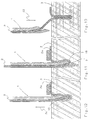
- FIG. 7 to 9 is the piercing of the thread 2 illustrated by the sewing material 3 in different working stages.
- Figure 7 shows the sewing material 3, for example. through several layers of mats on top of each other, For example, carbon fiber mats can be formed with a finished trained loop 31.
- the needle 1 has lengthways of the sewing material 3 moves one step further and is now in the direction indicated by an arrow 32 on the Material 3 too moved.
- the needle 1 opens with the tip 21 a stitch hole and pierces the sewing material 3.
- FIG. 8 illustrates, the thread lying on the sewing material 3 2a are fixed by a holder 33.
- the needle 1 pulls on the downward stroke with her eye 7 by means of the rounded Edge 18 thread 2 through the open stitch hole, the thread 2 runs with little friction in the thread groove 27.
- the hump 22 also fixes the thread 2 to the material to be sewn and prevents stabs that are already sticking to the material 3 Thread 2a is drawn.
- the hump 22 presses thread 2 to the wall of the taphole, i.e. to the Material 3 on.
- the loop 31 formed remains free stand below the material 3.
- the thread is free of play in the eye 7 and in the thread groove 27. It runs essentially stretched through the eye 7, being round, in the thread running direction inclined hole 8 the thread a certain Gives stability.
- the edge 15 moves the thread 2 in Direction of the eye 7 and prevents contact between the thread 2 and the sewing material 3. This promotes loop formation the needle of the invention 1.
- the thread 2 forming the loop 31 passes through eye 7 only once.
- the loop 31 is finished several layers of material are stabilized.
- the needle according to the invention enables this a controlled loop formation.
- FIGS. 10 to 12 the thread 2 is pierced illustrates a thicker sewing material 3, the needle 1 is not punctured. Otherwise the puncture process is correct largely with the process described above. However, no loops or loops are under the sewing material 3, but the pierced Thread 2 gets stuck in the stitch hole. That state is in Figure 10 for a previous puncture illustrated.
- the needle 1 begins in FIG. 10 with a Puncture direction according to arrow 32 a new stitching process. This is illustrated below in FIG. 11. How visible, the eye 7 pulls by means of the rounded edge 18 the thread 2 into the sewing material 3.
- the thread remains 2 stuck in the tap hole by holding it frictionally is. The comparatively lower friction between the thread 2 and the needle 1 allows them from the The stitch hole is pulled out in the direction of arrow 34, without taking the thread 2.
- a needle for inserting or piercing a thread 2 in or by sewing material 3 has a preferably cylindrical, inclined flat against the longitudinal direction of the needle long eye with a hump on the thread exit side is adjacent. This is used to clamp one in the material stitched thread in the stitch hole.
- a needle 1 with such a structure allows a good low-friction Guiding the thread 2, so that loop formation without additional Gripper is possible.
Landscapes
- Engineering & Computer Science (AREA)
- Textile Engineering (AREA)
- Sewing Machines And Sewing (AREA)
Applications Claiming Priority (2)
| Application Number | Priority Date | Filing Date | Title |
|---|---|---|---|
| DE19932288A DE19932288C2 (de) | 1999-07-10 | 1999-07-10 | Nähmaschinennadel mit verbesserter Schlingenbildung |
| DE19932288 | 1999-07-10 |
Publications (2)
| Publication Number | Publication Date |
|---|---|
| EP1069226A1 true EP1069226A1 (fr) | 2001-01-17 |
| EP1069226B1 EP1069226B1 (fr) | 2003-05-21 |
Family
ID=7914330
Family Applications (1)
| Application Number | Title | Priority Date | Filing Date |
|---|---|---|---|
| EP00106095A Expired - Lifetime EP1069226B1 (fr) | 1999-07-10 | 2000-03-30 | Aiguille de machine à coudre avec formation améliorée des boucles |
Country Status (4)
| Country | Link |
|---|---|
| US (1) | US6332416B1 (fr) |
| EP (1) | EP1069226B1 (fr) |
| DE (2) | DE19932288C2 (fr) |
| ES (1) | ES2199717T3 (fr) |
Families Citing this family (4)
| Publication number | Priority date | Publication date | Assignee | Title |
|---|---|---|---|---|
| DE10008447C2 (de) * | 2000-02-23 | 2002-07-25 | Groz Beckert Kg | Nähnadel zum multidirektionalen Nähen |
| JP4043319B2 (ja) * | 2002-08-23 | 2008-02-06 | オルガン針株式会社 | ミシン針 |
| JP2004141468A (ja) * | 2002-10-25 | 2004-05-20 | Organ Needle Co Ltd | ミシン針 |
| IL163209A (en) * | 2004-07-26 | 2009-08-03 | Yair Eilam | A sewing machine needle for sewing with a complex thread |
Citations (5)
| Publication number | Priority date | Publication date | Assignee | Title |
|---|---|---|---|---|
| US3523510A (en) * | 1969-03-20 | 1970-08-11 | Bigelow Sanford Inc | Tufting needle |
| DE2412062A1 (de) * | 1973-03-13 | 1974-10-10 | Manta Fa | Naehnadel |
| US4458614A (en) * | 1982-01-08 | 1984-07-10 | Organ Needle Co. Ltd. | Sewing machine needle |
| US4502403A (en) * | 1982-08-02 | 1985-03-05 | Wool Research Organization Of New Zealand (Inc.) | Tufting machine needles |
| EP0187925A1 (fr) * | 1984-12-14 | 1986-07-23 | Firma Jos. Zimmermann | Aiguille pour machine à touffeter |
Family Cites Families (4)
| Publication number | Priority date | Publication date | Assignee | Title |
|---|---|---|---|---|
| DE2834738C2 (de) * | 1977-08-10 | 1984-07-12 | Wool Research Organisation of New Zealand (Inc.), Lincoln, Canterbury | Nadel für Tuftingmaschinen |
| DE7923552U1 (de) * | 1979-01-25 | 1980-01-24 | Wool Research Organisation Of New Zealand Inc., Canterbury (Neuseeland) | Nadel fuer tufting-, naeh-, heftmaschinen u.dgl. |
| JPS6018774U (ja) * | 1983-07-14 | 1985-02-08 | 蛇の目ミシン工業株式会社 | ミシン針の構造 |
| BR9205263A (pt) * | 1991-05-10 | 1993-07-20 | Organ Needle | Processo de fabricacao de uma agulha para maquina de costura e a respectiva agulha |
-
1999
- 1999-07-10 DE DE19932288A patent/DE19932288C2/de not_active Expired - Fee Related
-
2000
- 2000-03-30 DE DE50002240T patent/DE50002240D1/de not_active Expired - Lifetime
- 2000-03-30 EP EP00106095A patent/EP1069226B1/fr not_active Expired - Lifetime
- 2000-03-30 ES ES00106095T patent/ES2199717T3/es not_active Expired - Lifetime
- 2000-07-10 US US09/613,506 patent/US6332416B1/en not_active Expired - Lifetime
Patent Citations (5)
| Publication number | Priority date | Publication date | Assignee | Title |
|---|---|---|---|---|
| US3523510A (en) * | 1969-03-20 | 1970-08-11 | Bigelow Sanford Inc | Tufting needle |
| DE2412062A1 (de) * | 1973-03-13 | 1974-10-10 | Manta Fa | Naehnadel |
| US4458614A (en) * | 1982-01-08 | 1984-07-10 | Organ Needle Co. Ltd. | Sewing machine needle |
| US4502403A (en) * | 1982-08-02 | 1985-03-05 | Wool Research Organization Of New Zealand (Inc.) | Tufting machine needles |
| EP0187925A1 (fr) * | 1984-12-14 | 1986-07-23 | Firma Jos. Zimmermann | Aiguille pour machine à touffeter |
Also Published As
| Publication number | Publication date |
|---|---|
| DE50002240D1 (de) | 2003-06-26 |
| US6332416B1 (en) | 2001-12-25 |
| EP1069226B1 (fr) | 2003-05-21 |
| DE19932288A1 (de) | 2001-01-25 |
| ES2199717T3 (es) | 2004-03-01 |
| DE19932288C2 (de) | 2001-11-29 |
Similar Documents
| Publication | Publication Date | Title |
|---|---|---|
| DE10305797B4 (de) | Nähinstrument mit verformbarer Nadel | |
| DE2552098C2 (de) | Nadel-Nahtmaterial-Kombination | |
| DE102005015064A1 (de) | Kompakte Nähstanze mit verformbarer Nadel | |
| DE2905226A1 (de) | Vorrichtung zum abschneiden und positionieren einer stichkette an einer naehmaschine | |
| EP1052323B1 (fr) | Aiguille de machine à coudre à chas mince | |
| EP1069226B1 (fr) | Aiguille de machine à coudre avec formation améliorée des boucles | |
| DE3642693C1 (de) | Hakennadel(auch Hakenroehrnadel)fuer Naeh-,Stick-,Heftmaschinen und dergl. | |
| DE10330660B3 (de) | Wundverschlussvorrichtung | |
| DE1585442A1 (de) | Zweiteilige Nadel zum Durchwirken von Textilgebilden | |
| WO2001017434A2 (fr) | Dispositif de guidage d'au moins deux sutures a travers une paroi, notamment une paroi arterielle d'un sujet, a proximite du bord d'une ouverture pratiquee dans la dite paroi | |
| EP1127973B1 (fr) | Aiguille de couture pour couture multidirectionnelle | |
| DE2339538A1 (de) | Nadel | |
| DD270326A5 (de) | Ueberwendlichstichtyp | |
| EP1052324B1 (fr) | Aiguille de machine à coudre avec chas à lèvres décalées | |
| EP1500734B1 (fr) | Aiguille à tête pointue | |
| DE102009004033B4 (de) | Nähmaschinennadel | |
| EP1577431B1 (fr) | Machine à coudre à point de chaîne | |
| DE19706086C2 (de) | Chirurgisches Hilfsmittel | |
| DE7306932U (de) | Gabelnadel | |
| DE202007015955U1 (de) | Nadel zum Durchstechen von Gewebe und Knorpel zum atraumatischen Transport eines Nahtfadens | |
| DE2146981A1 (de) | Schiebernadel fur maschenbildende Textilmaschinen, wie Kettenwirk , Nah wirk , Hakelgalon o dgl maschinen | |
| DE2745977A1 (de) | Vorrichtung zum gerichteten auslenken eines nadelfadens bei naehmaschinen, insbesondere vielnadelnaehmaschinen | |
| EP1620592B1 (fr) | Machine a coudre | |
| DE9214276U1 (de) | Laparoskopische Nähvorrichtung | |
| DE3512661C2 (fr) |
Legal Events
| Date | Code | Title | Description |
|---|---|---|---|
| PUAI | Public reference made under article 153(3) epc to a published international application that has entered the european phase |
Free format text: ORIGINAL CODE: 0009012 |
|
| AK | Designated contracting states |
Kind code of ref document: A1 Designated state(s): DE ES FR GB IT |
|
| AX | Request for extension of the european patent |
Free format text: AL;LT;LV;MK;RO;SI |
|
| 17P | Request for examination filed |
Effective date: 20010618 |
|
| AKX | Designation fees paid |
Free format text: DE ES FR GB IT |
|
| GRAH | Despatch of communication of intention to grant a patent |
Free format text: ORIGINAL CODE: EPIDOS IGRA |
|
| GRAH | Despatch of communication of intention to grant a patent |
Free format text: ORIGINAL CODE: EPIDOS IGRA |
|
| GRAA | (expected) grant |
Free format text: ORIGINAL CODE: 0009210 |
|
| AK | Designated contracting states |
Designated state(s): DE ES FR GB IT |
|
| REG | Reference to a national code |
Ref country code: GB Ref legal event code: FG4D Free format text: NOT ENGLISH |
|
| GBT | Gb: translation of ep patent filed (gb section 77(6)(a)/1977) |
Effective date: 20030521 |
|
| REF | Corresponds to: |
Ref document number: 50002240 Country of ref document: DE Date of ref document: 20030626 Kind code of ref document: P |
|
| REG | Reference to a national code |
Ref country code: ES Ref legal event code: FG2A Ref document number: 2199717 Country of ref document: ES Kind code of ref document: T3 |
|
| ET | Fr: translation filed | ||
| PLBE | No opposition filed within time limit |
Free format text: ORIGINAL CODE: 0009261 |
|
| STAA | Information on the status of an ep patent application or granted ep patent |
Free format text: STATUS: NO OPPOSITION FILED WITHIN TIME LIMIT |
|
| 26N | No opposition filed |
Effective date: 20040224 |
|
| REG | Reference to a national code |
Ref country code: FR Ref legal event code: PLFP Year of fee payment: 17 |
|
| REG | Reference to a national code |
Ref country code: FR Ref legal event code: PLFP Year of fee payment: 18 |
|
| REG | Reference to a national code |
Ref country code: FR Ref legal event code: PLFP Year of fee payment: 19 |
|
| PGFP | Annual fee paid to national office [announced via postgrant information from national office to epo] |
Ref country code: GB Payment date: 20180329 Year of fee payment: 19 |
|
| PGFP | Annual fee paid to national office [announced via postgrant information from national office to epo] |
Ref country code: IT Payment date: 20180321 Year of fee payment: 19 Ref country code: FR Payment date: 20180223 Year of fee payment: 19 |
|
| PGFP | Annual fee paid to national office [announced via postgrant information from national office to epo] |
Ref country code: ES Payment date: 20180402 Year of fee payment: 19 Ref country code: DE Payment date: 20180331 Year of fee payment: 19 |
|
| REG | Reference to a national code |
Ref country code: DE Ref legal event code: R119 Ref document number: 50002240 Country of ref document: DE |
|
| GBPC | Gb: european patent ceased through non-payment of renewal fee |
Effective date: 20190330 |
|
| PG25 | Lapsed in a contracting state [announced via postgrant information from national office to epo] |
Ref country code: DE Free format text: LAPSE BECAUSE OF NON-PAYMENT OF DUE FEES Effective date: 20191001 Ref country code: GB Free format text: LAPSE BECAUSE OF NON-PAYMENT OF DUE FEES Effective date: 20190330 |
|
| PG25 | Lapsed in a contracting state [announced via postgrant information from national office to epo] |
Ref country code: FR Free format text: LAPSE BECAUSE OF NON-PAYMENT OF DUE FEES Effective date: 20190331 Ref country code: IT Free format text: LAPSE BECAUSE OF NON-PAYMENT OF DUE FEES Effective date: 20190330 |
|
| REG | Reference to a national code |
Ref country code: ES Ref legal event code: FD2A Effective date: 20200728 |
|
| PG25 | Lapsed in a contracting state [announced via postgrant information from national office to epo] |
Ref country code: ES Free format text: LAPSE BECAUSE OF NON-PAYMENT OF DUE FEES Effective date: 20190331 |