EP1075125A2 - Assemblage à glissière pour un appareil de communication - Google Patents
Assemblage à glissière pour un appareil de communication Download PDFInfo
- Publication number
- EP1075125A2 EP1075125A2 EP00306453A EP00306453A EP1075125A2 EP 1075125 A2 EP1075125 A2 EP 1075125A2 EP 00306453 A EP00306453 A EP 00306453A EP 00306453 A EP00306453 A EP 00306453A EP 1075125 A2 EP1075125 A2 EP 1075125A2
- Authority
- EP
- European Patent Office
- Prior art keywords
- slide assembly
- housing part
- slide
- tracks
- entering information
- Prior art date
- Legal status (The legal status is an assumption and is not a legal conclusion. Google has not performed a legal analysis and makes no representation as to the accuracy of the status listed.)
- Granted
Links
Images



Classifications
-
- H—ELECTRICITY
- H04—ELECTRIC COMMUNICATION TECHNIQUE
- H04M—TELEPHONIC COMMUNICATION
- H04M1/00—Substation equipment, e.g. for use by subscribers
- H04M1/02—Constructional features of telephone sets
- H04M1/0202—Portable telephone sets, e.g. cordless phones, mobile phones or bar type handsets
- H04M1/0206—Portable telephones comprising a plurality of mechanically joined movable body parts, e.g. hinged housings
- H04M1/0208—Portable telephones comprising a plurality of mechanically joined movable body parts, e.g. hinged housings characterized by the relative motions of the body parts
- H04M1/0235—Slidable or telescopic telephones, i.e. with a relative translation movement of the body parts; Telephones using a combination of translation and other relative motions of the body parts
- H04M1/0237—Sliding mechanism with one degree of freedom
Definitions
- the invention relates to a communication unit having a housing part provided with means for entering information, and a slide cover that is slideable relative to the housing part. In one position the slide cover will at least partly cover the means for entering information while said means are freely accessible in another position of the slide cover.
- US 4.845.772 describes a phone having a pivotal flip that disables the keys when the flip is closed.
- GB 2.235.606 discloses a phone having a slide cover carrying a microphone.
- International design bulletin DM/039951 and DM/039675 shows two phones having detachable slides.
- Magneto-rheological fluids and electro-logical fluids used as motion controllers in dampers or chock-absorbers are well known in applications like automobile clutches, doors or lids.
- US 4.200.003 is shows a rotary viscous damper using a magnetic fluid as the damping medium. In this case the fluid is used to control the rotation motion of a rotor.
- US 5.257.681 is shown a segmented slim blade, where a magnetic field responsive fluid is used for motion control.
- JP-10009329 shows a spring box motion controller with the additional refinement of a completely flat version.
- An electro-viscous fluid is used for controlling the damping of the rotation of the rotary shaft. From US 5.736.798 a big magnetically controlled rotational damper is shown, where magnets can be moved closer to the fluid for adjustable braking action in exercise machines.
- An object of the invention is to provide a communication unit having a slide assembly with means for the slide assembly to be movable along a set of track on a housing part of the communication unit, where the slide assembly in an open position allows improved access to the information input means and still provides a good mechanical connection between the slide and the main body of the unit.
- a communication unit having a housing part provided with a set of converging tracks along which a slide assembly is sliding relative to the housing part.
- Said slide assembly includes a cover part and a spring. The slide cover is moved by the spring, which presses two slide wings of the slide assembly together.
- a left slide wing is fastened to the slide cover part, while a right slide wing is flexibly attached to the left wing to be able to glide inside the slide cover part and follow the conical shape of the housing part.
- bearings linear bearings, where each linear bearing consists of two guide ways and a set of caged baits (manufactured by e.g. Schneeberger, Switzerland or INA, Germany) between the guide ways.
- the spring is biased in the locked position of the slide.
- the slide assembly is moved by the biased spring.
- the objective is obtained by a communication unit having a housing part provided with a set of tracks along which a slide assembly is sliding relative to the housing part.
- the housing part is in this embodiment provided with a motor for moving the movable slide assembly along the tracks.
- a communication unit having a housing part provided with a set of tracks along which a slide assembly is sliding relative to the housing part.
- a spring box is mounted in the housing part, which is filled with a magneto-rheological fluid, where a gearwheel connected to said spring box moves the slide assembly.
- the slide assembly include two magnets, which affects the fluid in the spring box causing a damping or/and an accelerating effect on the slide assembly. A first magnet is placed so it is near the spring box in the closed position of the slide cover part, and a second magnet is placed so it is near the spring box in the open position of the slide cover part.
- the spring box housing may be built with polymer composites to make it lighter. According to an alternative embodiment the spring box could be mounted on the slide assembly, while the two magnets could be mounted on the housing part.
- Another object of the invention is to provide a communication unit having a slide assembly with means for the slide assembly to be movable along a set of track on a housing part of the communication unit.
- the slide assembly allows, in an open position, improved access to the information input means and still provides a good mechanical connection between the slide and the main body of the unit.
- the slide assembly includes means for reducing the friction, which occurs then the slide assembly moves between its two end positions, the open position and the closed position.
- a communication unit having a housing part provided with a set of tracks along which a slide assembly is sliding relative to the housing part, and said slide assembly includes a cover part and two slide assembly wings.
- the means for reducing the friction are linear bearings, which are located in the tracks on each side of the housing part and in the corresponding tracks on the slide assembly wings.
- Each linear bearing includes two guide ways and a set of caged balls between the guide ways.
- the means for decreasing the friction is using an internally lubricated polycarbonate on the sliding surfaces on both the housing part and the slide assembly.
- this object is obtained by having linear bearings, which are located in the tracks on each side of the housing part and in the corresponding tracks on the slide assembly wings.
- Each linear bearing includes two guide ways and a set of caged balls between the guide ways.
- this object is obtained by a two shot moulding method where the slide assembly is produced in two steps.
- the main part of the housing part and the slide assembly are produced by using an ABS/PC blend, and in a second injection moulding the sliding surfaces are produced by using an internally lubricated polycarbonate.
- An alternative embodiment of the invention is to form the internally lubricated polycarbonate to a film or a plate, and place this on the sliding surfaces. The sliding surface is then produced in the first injection moulding.
- the communication unit according to the invention will be described with reference to a hand portable phone, preferably a cellular phone.
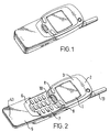
- a preferred embodiment of this phone is shown in fig. 1 and 2.
- the phone is shown with the slide in closed and open position in fig. 1 and 2, respectively.
- the phone is provided with a front cover 2 having a window frame 3 encircling the protection window of the display assembly 1.
- the phone is provided with a slide cover 5 snapped onto a slide frame 6 sliding in slide tracks 38 (see fig. 5) in the front cover 2 along a keypad area 7 and in extension thereof.
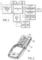
- the microphone 46 records the user's speech, and the analog signals formed thereby are A/D converted in an A/D converter (not shown) before the speech is encoded in an audio part 20.
- the encoded speech signal is transferred to the controller 18 (physical layer processor), which e.g. supports the GSM terminal software.
- the controller 18 also forms the interface to the peripheral units of the apparatus, including RAM and ROM memories 17a and 17b, a SIM card 16, the display 1 and the keypad 7 (as well as data, power supply, etc.).
- the controller 18 communicates with the transmitter/receiver circuit 19.
- the audio part 20 speech-decodes the signal, which is transferred from the controller 18 to the earpiece 21 via a D/A converter (not shown).
- Fig. 3 schematically shows the most important parts of a preferred embodiment of the phone, said parts being essential to the understanding of the invention.
- the preferred embodiment of the phone of the invention is adapted for use in connection with the GSM network, but, of course, the invention may also be applied in connection with other phone networks. It could be cellular networks, various forms of cordless phone systems or in dual band phones accessing sets of these systems/networks.
- the controller 18 is connected to the user interface. Thus, it is the controller 18, which monitors the activity in the phone and controls the display 1 in response thereto.
- Non user events comprise status change during call set-up, change in battery voltage, change in antenna conditions, message on reception of SMS, etc.
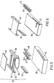
- Fig. 5 shows a preferred embodiment of the invention, where a housing part 30 has a wider portion nearest the display 1 and a narrower portion nearest the bottom end of the unit.
- the housing part 30 is provided with means, a keypad 7, for entering information (best shown in fig. 2).
- Said housing part 30 also includes a set of converging tracks, one track 31 on each long side of the housing part.
- a slide assembly 32 being moveable, said slide assembly includes a cover part 39, which at least partly covers said means 7 for entering information in one position of said slide assembly 32.
- the slide assembly 32 also includes a pair of slide wings 37 and 38, that are loosely connected to each other with a wire spring 36.
- the left slide wing 37 is fastened to the slide cover 39, while the right slide wing 38 is only fastened to the left slide wing through the wire spring 38.
- the movement of the slide assembly 32 along the housing part 30 is performed by the wire spring 36,which presses the slide wings 37 and 38 together and strives for moving the slide assembly towards the narrower end of the housing part 30.
- the movement starts when a slide release mechanism is initiated by pressing a push button, where after the wire spring 36 starts to move the slide cover into the open position where the keypad 7 may be accessed.
- the right slide 38 is able to glide inside the slide cover 39 during the movement to closely follow the converging tracks along the housing part 30.
- a linear bearing 33 which is located in each of the converging tracks 31 on the housing part 30 and in a corresponding set of tracks 40 on the slide wings 37 and 38.
- the linear bearing 33 aims to decrease the friction, which occurs then the slide assembly 32 moves between the open position and the closed position.
- the linear bearing 33 include two guide ways 34 and 35, and a set of caged balls 41 between said guide ways 34 and 35.
- Fig. 6 shows a housing part 30, whereon a gear motor 42 is mounted to move a slide assembly 43 between an open position (information could be entered) and a closed position (the keypad is partly covered).
- the slide assembly 43 is made in one piece, compared with the slide assembly 32 shown in fig. 5.
- linear bearings are located in a set of tracks on the housing part 30 and in a corresponding set of tracks on the slide assembly 43.
- the gear motor 42 could have a small rubber wheel on its shaft to move the slide assembly 43 from an open position to a closed position, and vice versa.
- Other solutions to move the slide assembly along the tracks could naturally be used.
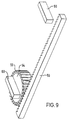
- fig. 7 is a communication unit 50 shown provided with a display unit 51 and a front cover 52. It is furthermore shown that the communication unit is provided with a slide cover 53, which can be moved between a closed and an open position. In fig. 7 the slide cover 53 is in a closed position, while it is in an open position in fig. 8.
- the slide cover 53 which is sliding along slide tracks (not shown in fig. 7 or 8), covers a keypad area 57 used for entering information to the communication unit. It is also shown in fig. 7 and 8 a spring box 54 mounted in a housing part cover by the front cover 52.
- the spring box 54 is filled with a magneto-rheological fluid and provided with cogs 55, which interacts with a cog provided rack 56, where said rack 56 is mounted on the slide cover 53 or on the slide frame 58.
- Two permanent magnets 59 and 60 are mounted on the backside (the side of the slide cover 53, which is closest to the keypad 57) of the slide cover 53.
- the magnet 59 is placed so that in the closed position of the slide cover is it near the spring box 54, see fig. 7.
- the other magnet 60 is placed so that in the open position of the slide cover 53 is it near the spring box 54 (see fig. 8).
- the magnets 59 and 60 increase the viscosity of the fluid inside the spring box 54, when the spring box 54 approach the magnets and causes a damping of the motion of the slide cover 53. Said magnets 59 and 60 finally lock the slide cover 53 in its end position.
- the slide begins opening or closing the motion of the slide cover 53 is slow due to the magnets, and after the first magnet is bypassed the motion accelerates because the viscosity of the fluid decreases inside the spring box 54.
- the motion approaches the end position of the opening or closing, the viscosity of the fluid increases inside the spring box 54 caused by the other magnet. This gives an elegant braking effect, and finally the spring box 54 locks the slide cover 53 into an open position or a closed position.
- the spring box with the two magnets are in other words used as an opener and as a motion controller.
- the viscosity of the magneto-rheological fluid in the spring can be adjusted using magnetic fields with different strengths. This makes it possible to change the characteristics of the fluids in the spring box during the motion if it includes magnets with different strength. If the viscosity of the fluid is low, the spring is a powerful opener and when the viscosity of the fluid is high the spring acts as a brake or a damper. In cases where the viscosity is very high, the spring acts as a locking device.
- the spring box 54 could be mounted on the slide cover 53, while the magnets 59 and 60 are mounted in the housing part of the communication unit.
- the function of the parts is the same as described above.
- FIG. 10 is an exploded view of the spring box 53 showing that it include a spring box housing 61, a spring 62, a shaft 63 and a lid 64.
- the same exploded view of the spring box is shown in fig. 11, but from a different angle.
- the spring box housing 61 can be made in polymer composites.
- the shaft 63 is attached to the housing part having a bearing to permit the rotation of the spring box 54. In the alternative embodiment the shaft 63 is attached to the slide cover 53.
- an internally lubricated polycarbonate is used on the sliding surfaces.
- the internally lubricated polycarbonate (PC) is applied onto the sliding surfaces by moulding.
- the main part of the housing part and the slide assembly is produced by using an ABS/PC blend and in a second injection moulding the sliding surfaces are produced by using an internally lubricated polycarbonate.
- the internally lubricated materials could also be produced into a thin film or plate, and then these polymer pieces are placed permanently on the sliding surfaces, which has been made in the first injection moulding is this case.
- the friction coefficient of the internally lubricated polycarbonates can be adjusted by using different internal lubrication agents. It could be agents, like polytetrafluorethane, silicone or a combination of both. Other materials having the same effect, without affecting other desired characteristics, could also be used.
Landscapes
- Engineering & Computer Science (AREA)
- Signal Processing (AREA)
- Telephone Set Structure (AREA)
- Casings For Electric Apparatus (AREA)
- Transmission Devices (AREA)
Applications Claiming Priority (2)
| Application Number | Priority Date | Filing Date | Title |
|---|---|---|---|
| GB9918672A GB2353170A (en) | 1999-08-06 | 1999-08-06 | Slide assembly for a communication unit |
| GB9918672 | 1999-08-06 |
Publications (3)
| Publication Number | Publication Date |
|---|---|
| EP1075125A2 true EP1075125A2 (fr) | 2001-02-07 |
| EP1075125A3 EP1075125A3 (fr) | 2003-12-03 |
| EP1075125B1 EP1075125B1 (fr) | 2005-11-23 |
Family
ID=10858785
Family Applications (1)
| Application Number | Title | Priority Date | Filing Date |
|---|---|---|---|
| EP00306453A Expired - Lifetime EP1075125B1 (fr) | 1999-08-06 | 2000-07-28 | Assemblage à glissière pour un appareil de communication |
Country Status (4)
| Country | Link |
|---|---|
| US (1) | US6782242B1 (fr) |
| EP (1) | EP1075125B1 (fr) |
| DE (1) | DE60024179T2 (fr) |
| GB (1) | GB2353170A (fr) |
Cited By (25)
| Publication number | Priority date | Publication date | Assignee | Title |
|---|---|---|---|---|
| WO2002089548A1 (fr) * | 2001-04-27 | 2002-11-07 | Nokia Corporation | Dispositif extensible |
| WO2002088568A1 (fr) * | 2001-04-27 | 2002-11-07 | Nokia Corporation | Module support a ressort |
| WO2003032612A3 (fr) * | 2001-10-09 | 2003-12-24 | Motorola Inc | Boitier pour dispositif electronique |
| US6993128B2 (en) | 2000-04-18 | 2006-01-31 | Nokia Mobile Phones, Ltd. | Portable electronic device |
| US7003334B2 (en) * | 2002-08-22 | 2006-02-21 | Samsung Electro-Mechanics Co., Ltd. | Auto-folder type cellular phone with variable opening and closing velocity |
| EP1524820A3 (fr) * | 2003-10-13 | 2006-03-15 | Hanbit Precision Co., Ltd. | Appareil pour ouvrir et fermer le couvercle d'un téléphone cellulaire |
| EP1638298A3 (fr) * | 2004-09-16 | 2006-05-17 | Sony Ericsson Mobile Communications Japan, Inc. | Terminal mobil avec un mécanisme automatique de coulissement |
| EP1662754A1 (fr) * | 2004-11-25 | 2006-05-31 | Samsung Electronics Co, Ltd | Module coulissant pour un terminal de communication portable de type coulissant |
| WO2006071408A1 (fr) * | 2004-12-28 | 2006-07-06 | Motorola Inc. | Mecanisme de glisseur |
| EP1528761A3 (fr) * | 2003-10-28 | 2006-11-02 | Lg Electronics Inc. | Terminal coulissant mobile de télécommunication avec mécanisme de glissement |
| EP1742448A1 (fr) | 2005-07-07 | 2007-01-10 | LG Electronics Inc. | Terminal mobile coulissant comprenant un dispositif amortisseur |
| GB2439549A (en) * | 2006-06-21 | 2008-01-02 | Nokia Corp | An electronic device sliding mechanism |
| US7363065B2 (en) | 2004-04-30 | 2008-04-22 | Samsung Electro-Mechanics Co., Ltd. | Automatic sliding-type mobile communication terminal, method of automatically driving sliding-type mobile communication terminal, and method of detecting incoming call to sliding-type mobile communication terminal |
| US7369884B2 (en) | 2004-06-22 | 2008-05-06 | Nokia Corporation | Slide assembly |
| WO2008092762A1 (fr) * | 2007-01-31 | 2008-08-07 | Schaeffler Kg | Téléphone portable mobile comprenant des paliers à roulement linéaires |
| WO2009089964A1 (fr) * | 2008-01-19 | 2009-07-23 | Schaeffler Kg | Appareil de communication mobile et son procédé de fabrication |
| CN100521891C (zh) * | 2005-05-17 | 2009-07-29 | 明基电通股份有限公司 | 双向滑盖式电子装置及双向滑动总成 |
| US7633402B2 (en) | 2003-04-15 | 2009-12-15 | Lg Electronics Inc. | Sliding mechanism |
| CN101351100B (zh) * | 2007-07-18 | 2010-09-29 | 华硕电脑股份有限公司 | 可调整平板式电子装置及其滑动装置 |
| EP2273770A1 (fr) * | 2009-07-09 | 2011-01-12 | HTC Corporation | Dispositif électronique et mécanisme coulissant semi-automatique correspondant |
| CN1997270B (zh) * | 2005-12-31 | 2011-03-16 | 阿尔派株式会社 | 具有可动前面板的电子设备 |
| EP1742449A3 (fr) * | 2005-07-09 | 2011-03-30 | LG Electronics Inc. | Module de coulissement et terminal portable comprenant un tel module |
| WO2011085752A1 (fr) * | 2010-01-14 | 2011-07-21 | Sony Ericsson Mobile Communications Ab | Charnière coulissante pour dispositif mobile comprenant un ensemble de crémaillère et pignon |
| US8326381B2 (en) | 2009-12-14 | 2012-12-04 | Research In Motion Limited | Cover plate assembly and method of operation of same |
| WO2012098473A3 (fr) * | 2012-06-06 | 2013-06-27 | Wasfi Alshdaifat | Téléphone à trois écrans équipé d'un moteur |
Families Citing this family (33)
| Publication number | Priority date | Publication date | Assignee | Title |
|---|---|---|---|---|
| US6980840B2 (en) * | 2000-01-24 | 2005-12-27 | Lg Electronics Inc. | Drawer-type mobile phone |
| JP2003204383A (ja) * | 2001-10-26 | 2003-07-18 | Nec Corp | 携帯電話機 |
| US6934560B2 (en) * | 2001-11-13 | 2005-08-23 | Telepaq Technology Inc. | System combining pager type personal digital assistant and mobile phone module |
| US6975889B2 (en) * | 2002-05-30 | 2005-12-13 | Quanta Computer Inc. | Cover-ejecting mechanism for a communication unit |
| US20040145572A1 (en) * | 2003-01-29 | 2004-07-29 | Arima Communication Corporation | Mobile telecommunication apparatus having hidden screen |
| KR20040027294A (ko) * | 2003-07-02 | 2004-04-01 | 포스텍전자주식회사 | 슬라이딩 힌지장치 |
| KR100531880B1 (ko) * | 2003-07-10 | 2005-11-29 | 엘지전자 주식회사 | 슬라이드형 휴대용 단말기의 개폐 장치 |
| TW200509589A (en) * | 2003-08-28 | 2005-03-01 | Waveplus Technology Co Ltd | Wireless local area network device |
| JP2005295312A (ja) * | 2004-04-01 | 2005-10-20 | Hitachi Ltd | 携帯無線装置 |
| KR100664983B1 (ko) * | 2004-06-23 | 2007-01-09 | 삼성전기주식회사 | 자동/반자동/수동 슬라이드형 이동통신단말기 |
| US7163248B2 (en) * | 2004-11-08 | 2007-01-16 | Lear Corporation | Automotive console with adjustable armrest |
| US7240941B2 (en) * | 2004-11-08 | 2007-07-10 | Lear Corporation | Vehicle storage assembly with adjustable door |
| DE102005004349B4 (de) * | 2004-12-21 | 2008-03-06 | Oechsler Ag | Mobiltelefon |
| US20060176654A1 (en) * | 2005-01-18 | 2006-08-10 | Amphenol-T&M Antennas | Sliding assembly for portable handset |
| US7447528B2 (en) * | 2005-04-12 | 2008-11-04 | Nokia Corporation | Multifunction electronic device |
| US20070060219A1 (en) * | 2005-09-09 | 2007-03-15 | Hung-Chih Lin | Sliding shell |
| CN1929725B (zh) * | 2005-09-09 | 2011-11-16 | 深圳富泰宏精密工业有限公司 | 铰链及使用该铰链的便携式电子装置 |
| US7570978B2 (en) * | 2005-12-01 | 2009-08-04 | Agere Systems Inc. | Apparatus and method for preventing an unintentional activation of a mobile communication device |
| JP4738161B2 (ja) * | 2005-12-21 | 2011-08-03 | 加藤電機株式会社 | 携帯機器のスライド機構及び携帯電話機 |
| TWM295704U (en) * | 2006-01-06 | 2006-08-11 | Jarllytec Co Ltd | Alignment mechanism for sliding track |
| US7996050B2 (en) * | 2006-02-28 | 2011-08-09 | Lg Electronics Inc. | Input device for an electronic device and electronic device having the same |
| US7860538B2 (en) * | 2006-02-28 | 2010-12-28 | Lg Electronics Inc. | Mobile terminal |
| US7953464B2 (en) * | 2006-07-13 | 2011-05-31 | Samsung Electronics Co., Ltd. | Sliding-type portable terminal |
| TW200907188A (en) * | 2007-08-02 | 2009-02-16 | Benq Corp | Sliding mechanism and method thereof and electronic device using the same |
| CN101426039A (zh) * | 2007-10-31 | 2009-05-06 | 鸿富锦精密工业(深圳)有限公司 | 便携式电子装置保护壳 |
| CN101621899A (zh) * | 2008-07-04 | 2010-01-06 | 深圳富泰宏精密工业有限公司 | 壳体组件 |
| CN101625069A (zh) * | 2008-07-11 | 2010-01-13 | 鸿富锦精密工业(深圳)有限公司 | 升降机构 |
| US7959201B2 (en) * | 2008-07-29 | 2011-06-14 | Honda Motor Co., Ltd. | Gear damper |
| CN101674712B (zh) * | 2008-09-08 | 2013-04-24 | 深圳富泰宏精密工业有限公司 | 滑盖机构及具该滑盖机构的便携式电子装置 |
| TWI407757B (zh) * | 2008-09-12 | 2013-09-01 | Fih Hong Kong Ltd | 滑蓋機構及具該滑蓋機構之攜帶型電子裝置 |
| CN101715281A (zh) * | 2008-10-06 | 2010-05-26 | 深圳富泰宏精密工业有限公司 | 滑动模组及应用该滑动模组的便携式电子装置 |
| CN102056443B (zh) * | 2009-10-27 | 2012-12-19 | 深圳富泰宏精密工业有限公司 | 滑盖结构及应用该滑盖结构的电子装置 |
| US11191528B2 (en) * | 2015-07-09 | 2021-12-07 | DePuy Synthes Products, Inc. | External hand control for surgical power tool |
Family Cites Families (28)
| Publication number | Priority date | Publication date | Assignee | Title |
|---|---|---|---|---|
| GB235606A (en) | 1923-12-19 | 1925-06-19 | Alexander Ferguson | Improvements in processes and apparatus for reducing ores and producing cement |
| US4200003A (en) * | 1976-03-29 | 1980-04-29 | Facet Enterprises, Inc. | Magnetic viscous damper |
| DE2901285A1 (de) * | 1978-01-26 | 1979-08-02 | Exxon Research Engineering Co | Lese-schreibkopfantrieb fuer flexible magnetplatten |
| US4845772A (en) | 1988-06-13 | 1989-07-04 | Motorola, Inc. | Portable radiotelephone with control switch disabling |
| US4809867A (en) * | 1986-12-23 | 1989-03-07 | Goldstar Co., Ltd. | Door opening/closing device for electronic appliances |
| GB2235606B (en) * | 1989-08-24 | 1994-03-30 | Technophone Ltd | Portable telephone |
| WO1992009163A1 (fr) * | 1990-11-16 | 1992-05-29 | Universal Cellular, Inc. | Boitier pour telephone portatif |
| JPH0645982A (ja) * | 1992-07-22 | 1994-02-18 | Sony Corp | 携帯型無線電話機 |
| US5257681A (en) | 1992-09-28 | 1993-11-02 | Trw Inc. | Apparatus for damping movement |
| JP3002985U (ja) * | 1994-02-18 | 1994-10-11 | 株式会社花絹コーポレーション | 携帯電話機 |
| JP2776753B2 (ja) * | 1994-11-24 | 1998-07-16 | 埼玉日本電気株式会社 | プラスチックシールド筐体 |
| US5697070A (en) * | 1995-06-05 | 1997-12-09 | Lucent Technologies, Inc. | Battery pack for portable transceiver |
| FR2738985B1 (fr) | 1995-09-14 | 1997-10-17 | Alcatel Mobile Comm France | Terminal de radiocommunication agence pour recevoir un capot de protection |
| US5736798A (en) | 1995-10-19 | 1998-04-07 | Eastman Kodak Company | Passive magnetic damper |
| GB2310561B (en) * | 1996-02-26 | 2000-06-21 | Nokia Mobile Phones Ltd | Radio telephone |
| GB2310560B (en) * | 1996-02-26 | 2000-07-12 | Nokia Mobile Phones Ltd | A radio telephone |
| US6409817B1 (en) | 1996-05-06 | 2002-06-25 | Agritec, Inc. | Fine-celled foam composition and method having improved thermal insulation and fire retardant properties |
| JPH109329A (ja) | 1996-06-20 | 1998-01-13 | Tokico Ltd | 電気粘性流体を用いたロータリダンパ |
| US6073027A (en) * | 1996-08-29 | 2000-06-06 | Bellsouth Corporation | Portable radiotelephone with sliding cover and automatic antenna extension |
| US5711610A (en) * | 1997-02-21 | 1998-01-27 | Optical Gaging Products, Inc. | Bearing assembly for linear bearing slide |
| US6101402A (en) * | 1997-09-04 | 2000-08-08 | Ericcson Inc. | Radiotelephone with sliding acoustic member |
| GB2334850A (en) * | 1998-02-27 | 1999-09-01 | Nokia Mobile Phones Ltd | A communication device with a keyboard cover mounted upon sliding rods |
| US6243595B1 (en) * | 1998-06-16 | 2001-06-05 | Nortel Networks Limited | Portable wireless communication device having an extendible section |
| GB2340333B (en) * | 1998-08-04 | 2002-07-31 | Nokia Mobile Phones Ltd | Radio telephone |
| US6208874B1 (en) * | 1998-11-02 | 2001-03-27 | Ericsson Inc. | Telephone assembly with automatic antenna adjustment |
| US6429817B1 (en) * | 2000-10-03 | 2002-08-06 | Bellsouth Intellectual Property Corporation | Retractable antenna for portable telephone |
| KR100417248B1 (ko) | 2001-03-22 | 2004-02-05 | 에스케이텔레텍주식회사 | 슬라이드 모듈을 이용한 슬라이드 타입 휴대폰 |
| US6751485B2 (en) | 2001-06-28 | 2004-06-15 | Nokia Corporation | Sounding alert for recent calls |
-
1999
- 1999-08-06 GB GB9918672A patent/GB2353170A/en not_active Withdrawn
-
2000
- 2000-07-28 DE DE60024179T patent/DE60024179T2/de not_active Expired - Fee Related
- 2000-07-28 EP EP00306453A patent/EP1075125B1/fr not_active Expired - Lifetime
- 2000-08-04 US US09/633,168 patent/US6782242B1/en not_active Expired - Lifetime
Cited By (38)
| Publication number | Priority date | Publication date | Assignee | Title |
|---|---|---|---|---|
| US6993128B2 (en) | 2000-04-18 | 2006-01-31 | Nokia Mobile Phones, Ltd. | Portable electronic device |
| JP2008035553A (ja) * | 2001-04-27 | 2008-02-14 | Nokia Corp | 2部分装置 |
| GB2391285B (en) * | 2001-04-27 | 2004-10-06 | Nokia Corp | Extendable device |
| GB2390662A (en) * | 2001-04-27 | 2004-01-14 | Nokia Corp | Spring barrel module |
| GB2391285A (en) * | 2001-04-27 | 2004-02-04 | Nokia Corp | Extendable device |
| US6695103B2 (en) | 2001-04-27 | 2004-02-24 | Nokia Corporation | Spring barrel module |
| US6733005B2 (en) | 2001-04-27 | 2004-05-11 | Nokia Corporation | Two-part device |
| GB2390662B (en) * | 2001-04-27 | 2004-10-06 | Nokia Corp | Spring barrel module |
| WO2002089548A1 (fr) * | 2001-04-27 | 2002-11-07 | Nokia Corporation | Dispositif extensible |
| WO2002088568A1 (fr) * | 2001-04-27 | 2002-11-07 | Nokia Corporation | Module support a ressort |
| WO2003032612A3 (fr) * | 2001-10-09 | 2003-12-24 | Motorola Inc | Boitier pour dispositif electronique |
| US7003334B2 (en) * | 2002-08-22 | 2006-02-21 | Samsung Electro-Mechanics Co., Ltd. | Auto-folder type cellular phone with variable opening and closing velocity |
| US7633402B2 (en) | 2003-04-15 | 2009-12-15 | Lg Electronics Inc. | Sliding mechanism |
| EP1469655A3 (fr) * | 2003-04-15 | 2009-12-16 | Lg Electronics Inc. | Mécanisme de coulissement pour un terminal de communication |
| EP1524820A3 (fr) * | 2003-10-13 | 2006-03-15 | Hanbit Precision Co., Ltd. | Appareil pour ouvrir et fermer le couvercle d'un téléphone cellulaire |
| EP1528761A3 (fr) * | 2003-10-28 | 2006-11-02 | Lg Electronics Inc. | Terminal coulissant mobile de télécommunication avec mécanisme de glissement |
| US7363065B2 (en) | 2004-04-30 | 2008-04-22 | Samsung Electro-Mechanics Co., Ltd. | Automatic sliding-type mobile communication terminal, method of automatically driving sliding-type mobile communication terminal, and method of detecting incoming call to sliding-type mobile communication terminal |
| US7369884B2 (en) | 2004-06-22 | 2008-05-06 | Nokia Corporation | Slide assembly |
| US7599721B2 (en) | 2004-09-16 | 2009-10-06 | Sony Ericsson Mobile Communications Japan, Inc. | Mobile terminal device including an elevating keyboard mechanism |
| EP1638298A3 (fr) * | 2004-09-16 | 2006-05-17 | Sony Ericsson Mobile Communications Japan, Inc. | Terminal mobil avec un mécanisme automatique de coulissement |
| EP1662754A1 (fr) * | 2004-11-25 | 2006-05-31 | Samsung Electronics Co, Ltd | Module coulissant pour un terminal de communication portable de type coulissant |
| WO2006071408A1 (fr) * | 2004-12-28 | 2006-07-06 | Motorola Inc. | Mecanisme de glisseur |
| CN100521891C (zh) * | 2005-05-17 | 2009-07-29 | 明基电通股份有限公司 | 双向滑盖式电子装置及双向滑动总成 |
| EP1742448A1 (fr) | 2005-07-07 | 2007-01-10 | LG Electronics Inc. | Terminal mobile coulissant comprenant un dispositif amortisseur |
| EP1742448B1 (fr) * | 2005-07-07 | 2010-05-26 | LG Electronics Inc. | Terminal mobile coulissant comprenant un dispositif amortisseur |
| US8073508B2 (en) | 2005-07-09 | 2011-12-06 | Lg Electronics Inc. | Slide module and mobile terminal having the same |
| EP1742449A3 (fr) * | 2005-07-09 | 2011-03-30 | LG Electronics Inc. | Module de coulissement et terminal portable comprenant un tel module |
| CN1997270B (zh) * | 2005-12-31 | 2011-03-16 | 阿尔派株式会社 | 具有可动前面板的电子设备 |
| GB2439549A (en) * | 2006-06-21 | 2008-01-02 | Nokia Corp | An electronic device sliding mechanism |
| GB2439549B (en) * | 2006-06-21 | 2010-11-03 | Nokia Corp | An electronic device sliding mechanism |
| WO2008092762A1 (fr) * | 2007-01-31 | 2008-08-07 | Schaeffler Kg | Téléphone portable mobile comprenant des paliers à roulement linéaires |
| CN101351100B (zh) * | 2007-07-18 | 2010-09-29 | 华硕电脑股份有限公司 | 可调整平板式电子装置及其滑动装置 |
| WO2009089964A1 (fr) * | 2008-01-19 | 2009-07-23 | Schaeffler Kg | Appareil de communication mobile et son procédé de fabrication |
| EP2273770A1 (fr) * | 2009-07-09 | 2011-01-12 | HTC Corporation | Dispositif électronique et mécanisme coulissant semi-automatique correspondant |
| US8279598B2 (en) | 2009-07-09 | 2012-10-02 | Htc Corporation | Electronic device and semi-auto sliding mechanism thereof |
| US8326381B2 (en) | 2009-12-14 | 2012-12-04 | Research In Motion Limited | Cover plate assembly and method of operation of same |
| WO2011085752A1 (fr) * | 2010-01-14 | 2011-07-21 | Sony Ericsson Mobile Communications Ab | Charnière coulissante pour dispositif mobile comprenant un ensemble de crémaillère et pignon |
| WO2012098473A3 (fr) * | 2012-06-06 | 2013-06-27 | Wasfi Alshdaifat | Téléphone à trois écrans équipé d'un moteur |
Also Published As
| Publication number | Publication date |
|---|---|
| DE60024179D1 (de) | 2005-12-29 |
| GB2353170A (en) | 2001-02-14 |
| EP1075125A3 (fr) | 2003-12-03 |
| EP1075125B1 (fr) | 2005-11-23 |
| GB9918672D0 (en) | 1999-10-13 |
| US6782242B1 (en) | 2004-08-24 |
| DE60024179T2 (de) | 2006-08-10 |
Similar Documents
| Publication | Publication Date | Title |
|---|---|---|
| US6782242B1 (en) | Slide assembly for a communication unit | |
| EP1760998B1 (fr) | Terminal de communication mobile pliable avec mécanisme d'ouverture automatique sous des angles divers | |
| EP1701519B1 (fr) | Terminal portable avec des boîtiers coulissants | |
| EP1777922B1 (fr) | Téléphone mobile du type coulissant | |
| KR101034951B1 (ko) | 댐퍼 장치 | |
| US20060046792A1 (en) | Hinge apparatus and methods therefor | |
| EP2146488B1 (fr) | Dispositif articulé biaxial et dispositif terminal portable | |
| GB2355044A (en) | Hinge with damping of spring biassed leaves. | |
| KR20050077004A (ko) | 휴대단말기슬라이드기구 | |
| US7866000B2 (en) | Swing hinge apparatus of portable terminal | |
| US20110130178A1 (en) | Sliding-type portable terminal | |
| WO2006035757A1 (fr) | Dispositif de charnière et mécanisme d’ouverture et de fermeture utilisant le dispositif de charnière | |
| WO2004084609A3 (fr) | Appareil et procede relatifs a un mecanisme de porte coulissante | |
| CA2580783A1 (fr) | Dispositif electronique avec trois couches mobiles | |
| EP0961459A3 (fr) | Mécanisme de charnière pour un téléphone portatif | |
| JP2003234809A (ja) | 携帯情報端末 | |
| EP1845696B1 (fr) | Terminal portable comportant un module à glissière | |
| EP1914963A1 (fr) | Ressort à torsions multiples et dispositif coulissant semi-automatique l'utilisant | |
| US8046034B2 (en) | Sliding-type portable terminal | |
| CN2777916Y (zh) | 盖体限位结构 | |
| JP2002250333A (ja) | ワンプッシュオープンヒンジ | |
| KR100606467B1 (ko) | 슬라이드 폰 | |
| US20080209683A1 (en) | Sliding Hinge Device, Personal Portable Device Having The Sliding Hinge Device And Method Of Manufacturing The Sliding Hinge Device | |
| EP1783986B1 (fr) | Appareil de coulissement pour un terminal portable du type coulissant | |
| KR20070019848A (ko) | 휴대용 단말기의 힌지 장치 |
Legal Events
| Date | Code | Title | Description |
|---|---|---|---|
| PUAI | Public reference made under article 153(3) epc to a published international application that has entered the european phase |
Free format text: ORIGINAL CODE: 0009012 |
|
| AK | Designated contracting states |
Kind code of ref document: A2 Designated state(s): AT BE CH CY DE DK ES FI FR GB GR IE IT LI LU MC NL PT SE |
|
| AX | Request for extension of the european patent |
Free format text: AL;LT;LV;MK;RO;SI |
|
| RAP1 | Party data changed (applicant data changed or rights of an application transferred) |
Owner name: NOKIA CORPORATION |
|
| PUAL | Search report despatched |
Free format text: ORIGINAL CODE: 0009013 |
|
| RIC1 | Information provided on ipc code assigned before grant |
Ipc: 7H 04M 1/02 A Ipc: 7F 16C 29/04 B |
|
| AK | Designated contracting states |
Kind code of ref document: A3 Designated state(s): AT BE CH CY DE DK ES FI FR GB GR IE IT LI LU MC NL PT SE |
|
| AX | Request for extension of the european patent |
Extension state: AL LT LV MK RO SI |
|
| 17P | Request for examination filed |
Effective date: 20040603 |
|
| AKX | Designation fees paid |
Designated state(s): DE FR IT NL |
|
| 17Q | First examination report despatched |
Effective date: 20040729 |
|
| GRAP | Despatch of communication of intention to grant a patent |
Free format text: ORIGINAL CODE: EPIDOSNIGR1 |
|
| GRAS | Grant fee paid |
Free format text: ORIGINAL CODE: EPIDOSNIGR3 |
|
| GRAA | (expected) grant |
Free format text: ORIGINAL CODE: 0009210 |
|
| AK | Designated contracting states |
Kind code of ref document: B1 Designated state(s): DE FR IT NL |
|
| GRAF | Information related to payment of grant fee modified |
Free format text: ORIGINAL CODE: EPIDOSCIGR3 |
|
| REF | Corresponds to: |
Ref document number: 60024179 Country of ref document: DE Date of ref document: 20051229 Kind code of ref document: P |
|
| ET | Fr: translation filed | ||
| PLBE | No opposition filed within time limit |
Free format text: ORIGINAL CODE: 0009261 |
|
| STAA | Information on the status of an ep patent application or granted ep patent |
Free format text: STATUS: NO OPPOSITION FILED WITHIN TIME LIMIT |
|
| 26N | No opposition filed |
Effective date: 20060824 |
|
| PGFP | Annual fee paid to national office [announced via postgrant information from national office to epo] |
Ref country code: DE Payment date: 20080807 Year of fee payment: 9 |
|
| PGFP | Annual fee paid to national office [announced via postgrant information from national office to epo] |
Ref country code: FR Payment date: 20080718 Year of fee payment: 9 Ref country code: IT Payment date: 20080729 Year of fee payment: 9 Ref country code: NL Payment date: 20080703 Year of fee payment: 9 |
|
| NLV4 | Nl: lapsed or anulled due to non-payment of the annual fee |
Effective date: 20100201 |
|
| REG | Reference to a national code |
Ref country code: FR Ref legal event code: ST Effective date: 20100331 |
|
| PG25 | Lapsed in a contracting state [announced via postgrant information from national office to epo] |
Ref country code: FR Free format text: LAPSE BECAUSE OF NON-PAYMENT OF DUE FEES Effective date: 20090731 |
|
| PG25 | Lapsed in a contracting state [announced via postgrant information from national office to epo] |
Ref country code: DE Free format text: LAPSE BECAUSE OF NON-PAYMENT OF DUE FEES Effective date: 20100202 |
|
| PG25 | Lapsed in a contracting state [announced via postgrant information from national office to epo] |
Ref country code: IT Free format text: LAPSE BECAUSE OF NON-PAYMENT OF DUE FEES Effective date: 20090728 |
|
| PG25 | Lapsed in a contracting state [announced via postgrant information from national office to epo] |
Ref country code: NL Free format text: LAPSE BECAUSE OF NON-PAYMENT OF DUE FEES Effective date: 20100201 |