EP1075829A2 - Badevorrichtung und -verfahren - Google Patents
Badevorrichtung und -verfahren Download PDFInfo
- Publication number
- EP1075829A2 EP1075829A2 EP00202827A EP00202827A EP1075829A2 EP 1075829 A2 EP1075829 A2 EP 1075829A2 EP 00202827 A EP00202827 A EP 00202827A EP 00202827 A EP00202827 A EP 00202827A EP 1075829 A2 EP1075829 A2 EP 1075829A2
- Authority
- EP
- European Patent Office
- Prior art keywords
- water
- hot
- supply
- base
- lotion
- Prior art date
- Legal status (The legal status is an assumption and is not a legal conclusion. Google has not performed a legal analysis and makes no representation as to the accuracy of the status listed.)
- Withdrawn
Links
- 238000003287 bathing Methods 0.000 title claims description 51
- 238000000034 method Methods 0.000 title claims description 18
- XLYOFNOQVPJJNP-UHFFFAOYSA-N water Substances O XLYOFNOQVPJJNP-UHFFFAOYSA-N 0.000 claims abstract description 208
- 239000006210 lotion Substances 0.000 claims description 69
- 239000007921 spray Substances 0.000 claims description 63
- 239000003599 detergent Substances 0.000 claims description 50
- 238000010438 heat treatment Methods 0.000 claims description 12
- 239000003595 mist Substances 0.000 claims description 12
- 238000001035 drying Methods 0.000 claims description 8
- 230000005855 radiation Effects 0.000 claims description 6
- 241001474374 Blennius Species 0.000 description 32
- 239000000344 soap Substances 0.000 description 30
- 239000000645 desinfectant Substances 0.000 description 29
- 239000007788 liquid Substances 0.000 description 18
- 238000010586 diagram Methods 0.000 description 8
- 230000008901 benefit Effects 0.000 description 7
- 230000000694 effects Effects 0.000 description 7
- 230000007246 mechanism Effects 0.000 description 7
- 239000002537 cosmetic Substances 0.000 description 4
- 239000000203 mixture Substances 0.000 description 4
- 230000003796 beauty Effects 0.000 description 3
- 230000036541 health Effects 0.000 description 3
- 230000008821 health effect Effects 0.000 description 3
- 208000031872 Body Remains Diseases 0.000 description 2
- 230000008878 coupling Effects 0.000 description 2
- 238000010168 coupling process Methods 0.000 description 2
- 238000005859 coupling reaction Methods 0.000 description 2
- 230000037213 diet Effects 0.000 description 2
- 235000005911 diet Nutrition 0.000 description 2
- 230000004060 metabolic process Effects 0.000 description 2
- 238000009423 ventilation Methods 0.000 description 2
- 238000005406 washing Methods 0.000 description 2
- 239000002351 wastewater Substances 0.000 description 2
- 238000000222 aromatherapy Methods 0.000 description 1
- 125000003118 aryl group Chemical group 0.000 description 1
- 239000012459 cleaning agent Substances 0.000 description 1
- 230000001143 conditioned effect Effects 0.000 description 1
- 235000008216 herbs Nutrition 0.000 description 1
- 230000004048 modification Effects 0.000 description 1
- 238000012986 modification Methods 0.000 description 1
- 239000011347 resin Substances 0.000 description 1
- 229920005989 resin Polymers 0.000 description 1
- 239000008400 supply water Substances 0.000 description 1
- 239000008399 tap water Substances 0.000 description 1
- 235000020679 tap water Nutrition 0.000 description 1
Images




Classifications
-
- A—HUMAN NECESSITIES
- A61—MEDICAL OR VETERINARY SCIENCE; HYGIENE
- A61H—PHYSICAL THERAPY APPARATUS, e.g. DEVICES FOR LOCATING OR STIMULATING REFLEX POINTS IN THE BODY; ARTIFICIAL RESPIRATION; MASSAGE; BATHING DEVICES FOR SPECIAL THERAPEUTIC OR HYGIENIC PURPOSES OR SPECIFIC PARTS OF THE BODY
- A61H33/00—Bathing devices for special therapeutic or hygienic purposes
- A61H33/06—Artificial hot-air or cold-air baths; Steam or gas baths or douches, e.g. sauna or Finnish baths
-
- A—HUMAN NECESSITIES
- A61—MEDICAL OR VETERINARY SCIENCE; HYGIENE
- A61H—PHYSICAL THERAPY APPARATUS, e.g. DEVICES FOR LOCATING OR STIMULATING REFLEX POINTS IN THE BODY; ARTIFICIAL RESPIRATION; MASSAGE; BATHING DEVICES FOR SPECIAL THERAPEUTIC OR HYGIENIC PURPOSES OR SPECIFIC PARTS OF THE BODY
- A61H35/00—Baths for specific parts of the body
-
- A—HUMAN NECESSITIES
- A61—MEDICAL OR VETERINARY SCIENCE; HYGIENE
- A61H—PHYSICAL THERAPY APPARATUS, e.g. DEVICES FOR LOCATING OR STIMULATING REFLEX POINTS IN THE BODY; ARTIFICIAL RESPIRATION; MASSAGE; BATHING DEVICES FOR SPECIAL THERAPEUTIC OR HYGIENIC PURPOSES OR SPECIFIC PARTS OF THE BODY
- A61H35/00—Baths for specific parts of the body
- A61H2035/004—Baths for specific parts of the body for the whole body except the head
-
- A—HUMAN NECESSITIES
- A61—MEDICAL OR VETERINARY SCIENCE; HYGIENE
- A61H—PHYSICAL THERAPY APPARATUS, e.g. DEVICES FOR LOCATING OR STIMULATING REFLEX POINTS IN THE BODY; ARTIFICIAL RESPIRATION; MASSAGE; BATHING DEVICES FOR SPECIAL THERAPEUTIC OR HYGIENIC PURPOSES OR SPECIFIC PARTS OF THE BODY
- A61H2201/00—Characteristics of apparatus not provided for in the preceding codes
- A61H2201/10—Characteristics of apparatus not provided for in the preceding codes with further special therapeutic means, e.g. electrotherapy, magneto therapy or radiation therapy, chromo therapy, infrared or ultraviolet therapy
-
- A—HUMAN NECESSITIES
- A61—MEDICAL OR VETERINARY SCIENCE; HYGIENE
- A61N—ELECTROTHERAPY; MAGNETOTHERAPY; RADIATION THERAPY; ULTRASOUND THERAPY
- A61N5/00—Radiation therapy
- A61N5/06—Radiation therapy using light
- A61N2005/0658—Radiation therapy using light characterised by the wavelength of light used
- A61N2005/0659—Radiation therapy using light characterised by the wavelength of light used infrared
-
- A—HUMAN NECESSITIES
- A61—MEDICAL OR VETERINARY SCIENCE; HYGIENE
- A61N—ELECTROTHERAPY; MAGNETOTHERAPY; RADIATION THERAPY; ULTRASOUND THERAPY
- A61N5/00—Radiation therapy
- A61N5/06—Radiation therapy using light
- A61N2005/0664—Details
- A61N2005/0668—Apparatus adapted for operation in a moist environment, e.g. bath or shower
Definitions
- the present invention relates to bathing methods and bathing apparatus to automatically bathe a human body, and specifically to bathing methods and bathing apparatus which can be appropriately used for a cosmetic purpose.
- Japanese Patent Laid-open No. 6-23009 discloses a shower bath apparatus having a structure in which shower water is flushed from above and below onto a subject to be bathed lying on a stretcher.
- conventional bathing apparatus are primarily to bathe people who need care and solely for a cleansing purpose. Therefore, conventional bathing apparatus cannot provide a subject to be bathed with cosmetic treatment or a health effect by relaxation or the like.
- An objective of the present invention is to solve the abovementioned problem by providing a bathing method and a bathing apparatus which can improve the beauty and health of a subject to be bathed.
- An embodimen of the invention is an apparatus comprising a base having an opening on the top; a body supporting member having a number of openings, placed inside of the base; a lid covering the opening of the base; a plurality of upper shower nozzles arranged on the lid; a plurality of lower shower nozzles arranged under the body supporting member in the base; a hot water supplying part; a hot-water supply route to connect a plurality of the upper shower nozzles and a plurality of the lower shower nozzles and the hot-water supplying part; and a heating means to heat a space formed by the base and the lid.
- a subject to be bathed can be provided with not only an effective cleansing but also a cosmetic treatment and a health effect by relaxation or the like. Thereby, the beauty and health of the subject to be bathed can be improved.
- the present invention includes various embodiments as follows;
- An embodiment of the invention is an apparatus wherein the heating means includes a far-infrared emission system to radiate far-infrared rays in a space formed by the base end the lid.
- the heating means includes a warm-air supply system having a warm-air generation part, a warm air ejection part to eject hot air into a space formed by the base and the lid, and a warm-air supply route to connect the warm-air ejection part and the warm-air generation part.
- Another embodiment of the invention is an apparatus further comprising a steam supply system to mix steam with warm air passing through the warm-air supply route.
- Another embodiment of the invention is an apparatus further comprising a cleansing agent reservoir to store a cleansing agent to cleanse a human body and a cleansing agent supplying means to mix the cleansing agent, stored in the cleansing agent reservoir, with hot-water passing through said hot-water supply route.
- Another embodiment of the invention is an apparatus further comprising a lotion reservoir to store lotion, spray nozzles to eject like a mist the lotion stored in the lotion reservoir onto a space formed by the base and the lid, and a lotion supply route to connect the spray nozzles and the lotion reservoir.
- Another embodiment of the invention is an apparatus further comprising a water-soluble-pack reservoir to store a water-soluble pack, and a water-soluble-pack supply route to connect the spray nozzles and the water-soluble-pack reservoir, spray nozzles to eject, like a mist, the water-soluble pack stored in said water-soluble pack reservoir onto a space formed by said base and said lid.
- Another embodiment of the invention is an apparatus wherein the spray nozzles comprises a plurality of upper spray nozzles arranged on the lid and a plurality of lower spray nozzles arranged under the body supporting member in the base.
- an embodiment of the invention is a bathing apparatus further comprising a swinging means to swing the upper shower nozzles and the lower shower nozzles.
- Another embodiment of the invention is an apparatus further comprising a swinging means to swing the spray nozzles.
- the present invention further includes an embodiment which is a method comprising a placement step to place a human body in a main apparatus consisting of a base having an opening on the top and a lid covering the opening of the base; a cleansing step to supply hot water and a cleansing agent to a human body in the main apparatus; a rinsing step to supply a hot water to a human body in the main apparatus.
- Another embodiment of the invention is a method further comprising a drying step to supply warm air to a human body in the main apparatus, after the rinsing step.
- Another embodiment of the invention is a method further comprising a lotion supplying step to supply lotion to a human body in the main apparatus, between the rinsing step and the drying step.
- Another embodiment of the invention is a method further comprising a water-soluble-pack supplying step to supply a water-soluble pack to a human body in the main apparatus, between the cleansing step and the heating step and/or between the heating step and the rinsing step.
- Another embodiment of the invention is a method wherein steam is admixed with the warm air in the heating step and/or the drying step.
- another embodiment of the invention is an apparatus comprising a main apparatus consisting of a base having an opening on the top and a body supporting member inside and a lid covering the opening of the base; a hot water supplying means to supply hot water to a human body in the main apparatus; a cleansing agent supplying means to supply a cleaning agent to a human body in the main apparatus; and a far-infrared supplying means to radiate far-infrared rays onto a human body in the main apparatus.
- Another embodiment of the invention is an apparatus further comprising a means to supply lotion to a human body in the main apparatus.
- Another embodiment of the invention is an apparatus further comprising a means to supply a water-soluble pack to a human body in the main apparatus.
- Another embodiment of the invention is an apparatus further comprising a means to admix steam with warm air supplied by the means to supply warm air.
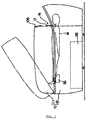
- Figure 1 is a general side view of a bathing apparatus of the present invention.
- Figure 2 is a top view of the apparatus without a lid 11.
- Figure 3 is a bottom view of the lid 11, i.e., a view of its back side.
- This bathing apparatus comprises a main apparatus 10 which consists of a base 12 having an opening on the top and a lid 11 covering the opening of the base 12. A subject to be bathed M is placed in the main apparatus 10.
- the lid 11 and the base 12 are made of molded resin. The lid 11 is hinged to the base 12.
- the base 12 is equipped with a supporting member 13 to support a subject to be bathed.
- This supporting member 13 comprises a frame 14 and a netlike member 15 bound to this frame 14. Numerous openings to pass hot water or the like described hereinafter are formed on this netlike member 15.
- the lid 11 is configured to cover most of the upper opening of the base 12. Further, the lid 11 has a waterproof curtain 17 which can be hung in front of an opening 16 formed on the opposite side of the hinge to the base 12.
- the subject to be bathed M enters or exits the main apparatus 10 when the lid 11 is open as shown with the double-dotted broken line in Figure 1.
- the subject to be bathed M enters the main apparatus 10 and lies on the supporting member 13, then the lid 11 is closed as shown with the solid line in Figure 1 such that only the head of the subject to be bathed M is exposed to external air while the trunk remains inside of the main apparatus 10.
- a plurality of far-infrared emission lamps 21 are mounted to radiate far-infrared rays onto the subject to be bathed M lying on the supporting member 13.
- a pair of right and left warm air ejection parts 22 to eject warm air mixed with steam into the main apparatus 10 are mounted under the supporting member 13 of the base 12. Further, a waste water recovering tank 28 to temporarily recover waste water is mounted at the bottom of the base 12.
- Three shafts 23 which can each turn around its axial center are located on the lid 11.
- Four upper nozzles 24 are mounted on each shaft 23.
- Three shafts 23 which can each turn around its axial center are also located under the supporting member 13 of the base 12 and four lower nozzles 25 are mounted on each shaft 23.
- These shafts 23 are turned around individual axial center by a shaft driving mechanism.
- the upper nozzles 24 and the lower nozzles 25 swing with the turning of the shafts 23.
- Figure 4 is a cross section view of the shaft driving mechanism to turn these shafts 23.
- One end of the shaft 23 pivots via a bearing 31 on the side wall 32 of the lid 11 or base 12, An O-ring 33 is placed between the shaft 32 and the bearing 31, to form an airtight connection between the outer perimeter of the shaft 23 and the inner perimeter of the bearing 31.
- the other end of the shaft 23 is connected, via a coupling 35, to a motor 35 mounted on the main apparatus. Thereby, the shaft 23 turns synchronously with the upper nozzles 24 (or lower nozzles 25) placed on it.
- These shafts 23 are set in the head-to-leg direction of the supine subject to be bathed M (parallel with the lying subject to be bathed M). Accordingly, as the abovementioned shafts 23 turn, the upper nozzles 24 (or lower nozzles 25) swing in a left-and-right motion (up-and-down direction in Figures 2 and 3).
- the abovementioned shafts 23 are cylindrical.
- One end of the shaft 23 is connected to a liquid supply system 41, described hereinafter, to supply hot water or the like to the upper nozzles 24 (or the lower nozzles 25).
- the other end of the shaft 23 is plugged by a stopper 36.
- hot water or the like supplied to the liquid supply system 41 runs through the shafts 23 and is ejected, like a shower, from the upper nozzles 24 (or lower nozzles 25) toward the subject to be bathed M.
- the hot water or the like is supplied to the entire body of the subject to be bathed M with the swinging motion of the upper nozzles 24 (or lower nozzles 25).
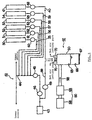
- FIG. 5 is a block diagram of the liquid supply system 41 and the steam/warm air supply system 42.
- the liquid supply system 41 has a hot-water supply route 44 to supply hot water stored in a hot-water storage tank 43, described in detail hereinafter, to the upper nozzles 24 and the lower nozzles 25.
- a solenoid valve 46 and a shower pump 45 are placed in this hot-water supply route 44. By operating the shower pump 45 while the solenoid valve 46 is opened, hot water stored in the hot-water storage tank 43 is moved to the upper nozzles 24 and the lower nozzles 25 and ejected from these upper nozzles 24 and lower nozzles 25 onto the subject to be bathed M in the main apparatus 10.
- the liquid supply system 41 has a cleansing agent reservoir 50 to store a cleansing agent to clean inside the main apparatus 10, a disinfectant reservoir 51 to store a disinfectant to disinfect inside the main apparatus 10, a body soap reservoir 52 to store a body soap to cleanse the human body, a lotion reservoir 53 to store lotion and a seaweed-pack reservoir 54 to store a seaweed pack as a water-soluble pack.
- the abovementioned cleansing agent reservoir 50 is connected to the hot-water supply route 44 via a cleansing-agent supply route 55.
- a tube pump 60 to move a small amount of cleansing agent is placed inside the cleansing-agent supply route 55.
- the cleansing agent stored in the cleansing agent reservoir 50 is moved toward the hot-water supply route 44 and a desired amount of the cleansing agent is admixed with hot water and thus can be supplied to the upper nozzles 24 and the lower nozzles 25.
- the abovementioned disinfectant reservoir 51 is connected to the hot-water supply route 44 via a disinfectant supply route 56.
- a tube pump 61 to move a small amount of disinfectant is placed inside the disinfectant supply route 56.
- the tube pump 61 the disinfectant stored in the disinfectant reservoir 51 is moved toward the hot-water supply route 44 and a desired amount of the disinfectant is admixed with hot water and thus can be supplied to the upper nozzles 24 and the lower nozzles 25.
- the abovementioned body soap reservoir 52 is connected to the hot-water supply route 44 via a body-soap supply route 57.
- a tube pump 62 to move a small amount of body soap is placed inside the body-soap supply route 57.
- the tube pump 62 by operating the tube pump 62, the body soap stored in the body soap reservoir 52 is moved toward the hot-water supply route 44 and a desired amount of the body soap is admixed with hot water and thus can be supplied to the upper nozzles 24 and the lower nozzles 25.
- the abovementioned lotion reservoir 53 is connected to the hot-water supply route 44 via a lotion supply route 58.
- a tube pump 63 to move a small amount of lotion is placed inside the lotion supply route 58.
- the tube pump 63 by operating the tube pump 63, the lotion stored in the lotion reservoir 53 is moved toward the hot-water supply route 44 and a desired amount of the lotion is admixed with hot water and thus can be supplied to the upper nozzles 24 and the lower nozzles 25.
- seaweed pack reservoir 54 is connected to the hot-water supply route 44 via a seaweed-peck supply route 59.
- a tube pump 64 to move a small amount of seaweed pack is placed inside the seaweed-pack supply route 59.
- the seaweed pack stored in the seaweed-pack reservoir 54 is moved toward the hot-water supply route 44 and a desired amount of the seaweed pack is admixed with hot water and thus can be supplied to the upper nozzles 24 and the lower nozzles 25.
- lotion and a seaweed pack are admixed with hot water to supply them to the body.
- the lotion or seaweed pack can be directly supplied to the upper nozzles 24 and the lower nozzles 25 from the lotion reservoir 53 or the seaweed-pack reservoir 54.
- special nozzles can be used instead of the upper nozzles 24 and the lower nozzles 25.
- a steam/warm air supply system 42 has a warm air generation part 80, consisting of a ventilator 68 and a heater 69, and a steam generation part 90 connected to this warm air generation part 80 via a ventilating route 98.
- a heater 67 is built in at the bottom of the abovementioned steam generation part 90.
- a pair of upper and lower water level sensors 65, 66 are mounted on the side wall of the steam generation part 90. Further, ventilating pipes 70 connected to a pair of warm air ejection parts 22 placed on the base 12 are located on the top of the steam generation part 90.
- the steam generation part 90 is connected to the abovementioned hot-water storage tank 43 via a supply route 99.
- hot water stored in the hot-water storage tank 43 can be moved to the steam generation part 90 by operating the tube pump 49.
- Hot water so moved is then stored in the steam generation part 90.
- the level of hot water is monitored and controlled by the pair of upper and lower water level sensors 65, 66.
- Hot water stored in the steam generation part 90 is then heated by the heater 67 to generate steam.
- This steam is mixed with warm air generated by the warm air generation part 80 and supplied via the ventilating pipe 70 to the pair of warm air ejection parts 22 placed inside the base 12.
- the steam/warm air generating system 42 has an aroma reservoir 47 to store an extract of aromatic herbs such as aroma oil used in aromatherapy (referred to as "aroma" in this specification).
- This aroma reservoir 47 is connected to the steam generation part 90 via an aroma supply route 40.
- a tube pump 48 to move a small amount of aroma is located in the aroma supply route 40.
- aroma stored in the aroma reservoir 47 can be moved to the steam generation part 90 by operating the tube pump 48.
- Aroma moved from the aroma reservoir 47 to the steam generation part 90 is added dropwise into hot water stored in the steam generation part 90.
- the aroma is vaporized with the hot water using the heater 67.
- the vaporized aroma is admixed with warm air generated by the warm air generation part 80 and supplied via the ventilating pipes 70 to a pair of warm air ejection parts 22 placed inside the base 12.
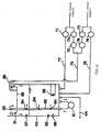
- FIG. 6 is a block diagram of the hot-water storage tank 43 along with a hot water and water supply system.
- This hot-water storage tank 43 is to store hot water at a specified temperature.
- This hot-water storage tank 43 is connected via a pipe 77 to a hot-water supply source to supply hot water.
- a switching valve 71 is set in this pipe 77.
- this hot-water storage tank 43 is connected via a pipe 78 to a water supply source to supply water at a normal temperature (tap water).
- a switching valve 76 is placed in this pipe 78.
- this hot-water storage tank 43 is also connected to a hot-water supply source and a water supply source via a pipe 79.
- a mixing valve mechanism consisting of a pair of flow control valves 72, 74 and a pair of switching valves 73 74 are placed between the pipe 79 and the hot-water supply source and the water supply source.
- the pair of flow rate control valves 72, 74 can control the degree of opening based on the temperature of hot water detected by a temperature sensor 91 described hereinafter.
- hot water at an approximately constant temperature can be supplied in the pipe 79.
- the hot-water storage tank 43 is equipped with a circulation pump 81 and a circulation pipe 82 to circulate hot water stored in the hot-water storage tank 43 and the temporary store tray 85 located in the upper part. Hot water stored in the hot-water storage tank 43 is sucked from the bottom by operating the circulation pump 81 into the circulation pipe 82. Then, a part of the hot water flows out from a plurality of the openings 84 formed on the circulation pipe 82 and the remaining part flows into the temporary store tray 85. The hot water flowing into the temporary store tray 85 overflows from the top and then runs down into the hot-water storage tank 43.
- a temperature sensor 91 to measure the temperature of the hot water in the temporary store tray 85 is mounted on the side wall of the temporary store tray 85.
- a temperature sensor 92 to measure the temperature of the hot water in the hot-water storage tank 43 is equipped on the side wall of the hot-water storage tank 43.
- a pair of upper and lower water level sensors 87, 88 to monitor the level of hot water in the hot-water storage tank 43 and a heater 86 to heat hot water in the hot-water storage tank 43 are mounted on the side wall of the hot-water storage tank 43.
- hot water from the hot-water supply source or normal temperature water from the water source is supplied to the hot-water storage tank 43 by opening the switching valves 71 and 76 while keeping the switching valves 73 and 75 closed.
- the switching valves 71 and 76 close.
- the hot water in the hot-water storage tank 43 is circulated by the circulation pump 81 and is heated by the heater 86.
- the temperature of the hot water in the hot water storage tank 43 is detected by the temperature sensor 92.
- the temperature of the hot water in the hot-water storage tank 43 is kept constant by controlling the heater 86 based on the detected value.
- FIG. 7 is a block diagram showing the main electrical configuration of the bathing apparatus according to the present invention.
- the bathing apparatus has a control unit 100 consisting of a CPU 101 to carry out logical calculations, a ROM 102 to store operating programs necessary to control the apparatus and a RAM 103 to temporarily store data or the like.
- This control unit 100 is connected via an interface 104 to an operation control unit 106 to control operation of the abovementioned sensors, pumps, valves and heaters. Further, the control unit 100 is connected via the interface 104 to an operation panel 105, which is mounted on the lid 11 (see Figure 1), to input various data.
- a prescription for bathing is input via the operation panel 105 by the subject to be bathed M or an operator.
- hot water at a specified temperature is filled into the hot-water storage tank 43 and steam is being generated from the aroma-containing hot water in the steam generation part 90.
- the lid 11 is opened as shown with the double-dotted broken line in Figure 1.
- the subject to be bathed M then enters the main apparatus 10 and lies on the supporting member 13, after which the 11 is closed as shown with the solid line in Figure 1.
- the waterproof curtain 17 is placed around the neck of the subject to be bathed M. In this state, there is a very little opening around the neck of the subject to be bathed M.
- Bathing starts in this state.
- First the shower pump 45 is operated while the solenoid valve 46 in the liquid supply system 41 remains open. Thereby, hot water is supplied from the hot-water storage tank 43 to the upper nozzles 24 and the lower nozzles 25, then ejected onto the subject to be bathed M.
- the motor 35 shown in Figure 4 is driven to turn each shaft 23 so as to cause the upper nozzles 24 and the lower nozzles 25 to swing in the left-right direction relative to the subjects to be bathed M. Hot water is supplied over the entire body of the subject to be bathed M by this swinging. Thus, the swinging can also improve the showering effect with hot water supplied from the upper nozzles 24 and the lower nozzles 25.
- the tube pump 62 is operated. Thereby, the body soap stored in the body soap reservoir 52 is supplied via the body-soap supply route 57 to the hot-water supply route 44. This body soap is then admixed with the hot water passing through the hot-water supply route 44. Thereby the body soap is supplied, like a shower, to the entire body of the subject to be bathed M from the swinging upper nozzles 24 and lower nozzles 25 to cleanse the body of the subject to be bathed M.
- the operation of the tube pump 62 is stopped. Thereby, only hot water is supplied, like a shower, from the swinging upper nozzles 24 and lower nozzles 25, to the entire body of the subject to be bathed M. The body soap supplied to the subject to be bathed M is removed by this hot water shower.
- the tube pump 64 is then operated. Thereby, the seaweed pack stored in the seaweed-pack reservoir 54 is supplied via the seaweed-pack supply route 59 to the hot-water supply route 44. Since the seaweed pack is water soluble, it can be readily mixed with hot water. This seaweed pack is then admixed with the hot water passing through the hot-water supply route 44. Thereby, the seaweed pack is supplied, like a shower, to the entire body of the subject to be bathed M from the swinging upper nozzles 24 and lower nozzles 25. This seaweed pack can make the skin of the subject to be bathed M healthy.
- the shower pump 45 and the tube pump 64 are stopped.
- the ventilator 68 and the heater 69 are started to supply warm air from the warm air generation part 80 to the steam generation part 90.
- aroma-containing steam is admixed with the warm air generated in the warm air generation part 80.
- This aroma-containing steam is supplied, via the ventilation pipe 70, to the pair of the warm air ejection parts 22 placed in the base 12, and filled into the main apparatus 10.
- a plurality of far-infrared emission lamps 21 placed in the back side of the lid 11 are lit.
- Far-infrared rays from the far-infrared emission lamps 21 radiate the subject to be bathed M.
- the body, to the inside, of the subject to be bathed M is warmed up from the inside and perspiration is enhanced by the warm air mixed with steam and far-infrared radiation. This promotes body metabolism to improve the effect of one's diet.
- the body of the subject to be bathed M can be warmed up only by hot water mixed with steam or by far-infrared radiation only.
- the aroma-containing steam filled into the main apparatus 10 is released outside through the narrow opening around the neck of the subject to be bathed M.
- the subject to be bathed M can fully inhale the aroma containing steam.
- the relaxation effect on the subject to be bathed M can be improved.
- warm air generation by the warm air generation part 80 is stopped and at the same time, the far-infrared emission lamps 21 are turned off.
- the shower pump 45 and the tube pump 64 are restarted to supply a seaweed pack, like a shower, onto the entire body of the subject to be bathed M.
- the tube pump 64 is stopped. Thereby, only hot water is supplied like a shower via the swinging upper nozzles 24 and lower nozzles 25 onto the entire body of the subject to be bathed M. By this hot water shower, the seaweed pack supplied on the subject to be bathed M is removed.
- the tube pump 63 is then started. Thereby, lotion stored in the lotion reservoir 53 is supplied to the hot-water supply route 44 via the lotion supply route 58. This lotion is then admixed with hot water passing through the hot-water supply route 44. Thereby, the lotion is supplied, like a shower, via the swinging upper nozzles 24 and lower nozzles 25 onto the entire body of the subject to be bathed M. This lotion can maintain the skin of the subject to be bathed M in its optimal condition.
- the shower pump 45 and the tube pump 64 are stopped.
- the ventilator 68 and the heater 69 are then started to restart warm air generation by the warm air generation part 80. Thereby, the body of subject to be bathed M is warmed up and drying of water drops on the body of the subject to be bathed M can be enhanced.
- the lid 11 is moved to the open position, as shown with the double-dotted broken line in Figure 1, to let out the subject to be bathed M.
- the inside of the main apparatus 10 is washed after completion of the abovementioned bathing procedure.
- the lid 11 is placed in the closed position as shown with the solid line in Figure 1, after which the shower pump 45 and the tube pump 60 are started, Thereby, a cleansing agent stored in the cleansing agent reservoir 50 is supplied to the hot-water supply route 44 via the cleansing-agent supply route 55. This cleansing agent is then admixed with the hot water passing through the hot-water supply route 44.
- the tube pump 60 is stopped and the tube pump 61 is started.
- a disinfectant stored in the disinfectant reservoir 51 is supplied via the disinfectant supply route 56 to the hot-water supply route 44.
- this disinfectant is admixed with hot water passing through the hot-water supply route 44.
- the main apparatus 10 can entirely be disinfected with the disinfectant.
- the warm air mixed with stream is supplied to the main apparatus 10 by generating warm air in the warm air generation part 80, only in necessary steps.
- the warm air mixed with, stream can be filled constantly into the main apparatus 10 by operating the warm air generation part 80 in every step.
- Three shafts 23 which can each turn around its axial center are located on the lid 11.
- Upper shower nozzles 24a are mounted on the shafts 23 located on both sides.
- Upper spray nozzles 24b are mounted on the shaft 23 located in the center.
- Three shafts 23 which can each turn around its axial center are also located under the supporting member 13 in the base 12.
- Lower shower nozzles 25a are mounted on the shafts 23 located on both sides.
- Lower spray nozzles 25b are mounted on the shaft 23 located in the center.
- the abovementioned upper shower nozzles 24a and lower shower nozzles 25a are to eject hot water or the like, described hereinafter, like a shower. Further, the abovementioned upper spray nozzles 24b and lower spray nozzles 25b are to eject lotion or a seaweed pack, described hereinafter, like a mist.
- Figure 4 is a cross section view of the shaft driving mechanism to turn these shafts 23.
- the upper shower nozzles 24a and the upper spray nozzles 24b are shown with symbol 24, and the lower shower nozzles 25a and the lower spray nozzles 25b are shown by symbol 25.
- One end of the shaft 23 pivots via a bearing 31 on the side wall 32 of the lid 11 or base 12.
- An O-ring 33 is placed between the shaft 32 and the bearing 31 to form an airtight connection between the outer perimeter of the shaft 23 and the inner perimeter of the bearing 31.
- the other end of the shaft 23 is connected, via a coupling 35, to a motor 35 mounted on the main apparatus.
- the shaft 23 turns synchronously with the upper shower nozzles 24a (or lower shower nozzles 25a, upper spray nuzzles 24b, lower spray nozzles 25b) mounted on it.
- These shafts 23 are set in the head-to-leg direction of of the subject to be bathed M (parallel with the supine subject to be bathed M). Accordingly, as the abovementioned shafts 23 turn, the upper shower nozzles 24a (or lower shower nozzles 25a, upper spray nozzles 24b, lower spray nozzles 25b) swing in a left-and-right motion (up-and-down direction in Figures 2 and 8).
- the abovementioned shafts 23 are cylindrical having one end plugged by a stopper 36.
- the shafts 23 on both sides are connected to a hot-water supply route 44, described hereinafter, to supply hot water or the like to the upper shower nozzles 24a (or lower shower nozzles 25a).
- hot water or the like supplied from the hot-water supply route 44 runs through the shafts 23 and is ejected like a shower from the upper shower nozzles 24a (or lower shower nozzles 25a) toward the subject to be bathed M.
- the hot water or the like is supplied on the entire body of the subject to be bathed M with the swinging motion of the upper shower nozzles 24a (or lower shower nozzles 25a).
- the shafts 23 in the center is connected to a lotion supply route 55 to supply lotion or a seaweed-pack supply route 56 to supply a seaweed pack, to the upper spray nozzles 24b (or lower spray nozzles 25a).
- the lotion or the seaweed pack supplied from the lotion supply route 55 or the seaweed supply route 56 runs through the shafts 23 and is ejected like a mist from the upper spray nozzles 24b (or lower spray nozzles 25b) toward the subject to be bathed M.
- the lotion of the seaweed pack is supplied to the entire body of the subject to be bathed M with the swinging motion of the upper spray nozzles 24b (or lower spray nozzles 25b).
- FIG. 9 is a block diagram of the liquid supply system 41 and the steam/warm-air supply system 42.
- the liquid supply system 41 has a hot-water supply route 44 to supply hot water stored in a hot-water storage tank 43, described in detail hereinafter, to the upper shower nozzles 24a and the lower shower nozzles 25a.
- a solenoid valve 46 and a shower pump 45 are placed in this hot-water supply route 44. By operating the shower pump 45 while the solenoid valve 46 is opened, hot water stored in the hot-water storage tank 43 is moved to the upper shower nozzles 24a and the lower shower nozzles 25a and ejected from these upper shower nozzles 24a and lower shower nozzles 25a onto the subject to be bathed M in the main apparatus 10.
- the liquid supply system 41 has a cleansing agent reservoir 53 to store a cleansing agent to clean inside the main apparatus 10, a disinfectant reservoir 54 to store a disinfectant to disinfect inside the main apparatus 10, a body soap reservoir 52 to store a body soap to wash human bodies, a lotion reservoir 50 to store lotion and a seaweed-pack reservoir 51 to store a seaweed pack as a water-soluble pack.
- the abovementioned cleansing agent reservoir 53 is connected to the hot-water supply route 44 via a cleansing-agent supply route 58.
- a tube pump 63 to move a small amount of cleansing agent is placed inside the cleansing-agent supply route 58.
- the cleansing agent stored in the cleansing agent reservoir 53 is moved toward the hot-water supply route 44 and a desired amount of the cleansing agent is mixed with hot water and thus can be supplied to the upper shower nozzles 24a and the lower shower nozzles 25a.
- the abovementioned disinfectant reservoir 54 is connected to the hot-water supply route 44 via a disinfectant supply route 59.
- a tube pump 64 to move a small amount of cleansing agent is placed inside the disinfectant supply route 59.
- the abovementioned body soap reservoir 52 is connected to the hot-water supply route 44 via a body soap supply route 57.
- a tube pump 62 to move a small amount of body soap is placed inside the body soap supply route 57.
- the tube pump 62 by operating the tube pump 62, the body soap stored in the body soap reservoir 52 is moved toward the hot-water supply route 44 and a desired amount of the body soap is mixed with hot water and thus can be supplied to the upper shower nozzles 24a and the lower shower nozzles 25a.
- the abovementioned lotion reservoir 50 is connected to the upper spray nozzles 24b and the lower spray nozzles 25b via a lotion supply route 55.
- a tube pump 60 to move a small amount of lotion is placed inside the lotion supply route 58.
- the lotion stored in the lotion reservoir 50 is moved toward the upper spray nozzles 24b and the lower spray nozzles 25b and a desired amount of the lotion can be ejected from the upper spray nozzles 24b and the lower spray nozzles 25b.
- the abovementioned seaweed-pack reservoir 51 is connected to the upper spray nozzles 24b and the lower spray nozzles 25b via a seaweed-pack supply route 56.
- a tube pump 61 to move a small amount of seaweed pack is placed inside the seaweed-pack supply route 56.
- the seaweed pack stored in the seaweed-pack reservoir 51 is moved toward the upper spray nozzles 24b and the lower spray nozzles 25b and a desired amount of the seaweed pack can be ejected from the upper spray nozzles 24b and the lower spray nozzles 25b.
- a prescription for bathing is input via the operation panel 105 by the subject to be bathed M or an operator.
- hot water at a specified temperature is filled into the hot-water storage tank 43 and steam is being generated from the aroma-containing hot water in the steam generation part 90.
- the lid 11 is opened as shown with the double-dotted broken line in Figure 1.
- the subject to be bathed M then enters the main apparatus 10 and lies on the supporting member 13, after which the lid 11 is closed as shown with the solid line in Figure 1.
- the waterproof curtain 17 is placed around the neck of the subject to be bathed M. In this state, there is a very little opening around the neck of the subject to be bathed M.
- the shower pump 45 is operated while the solenoid valve 41 in the liquid supply system 41 remains open. Thereby, hot water is supplied from the hot-water storage tank 43 to the upper shower nozzles 24a and the lower shower nozzles 25a, then ejected onto the subject to be bathed M.
- the motor 33 shown in Figure 4 is driven to turn each shaft 23 so as to cause the upper shower nozzles 24a and the lower shower nozzles 25a to swing in the left-right direction relative to the subject to be bathed M. Hot water is supplied onto the entire body of the subject to be bathed M by this swinging.
- the swinging can also improve the showering effect with hot water supplied from the upper shower nozzles 24a and the lower shower nozzles 25a.
- the tube pump 62 is operated. Thereby, the body soap stored in the body soap reservoir 52 is supplied via the body soap supply route 57 to the hot-water supply route 44. This body soap is then mixed with the hot water passing through the hot-water supply route 44. Thereby, the body soap is supplied, like a shower, to the entire body of the subject to be bathed M from the swinging upper shower nozzles 24a and the lower shower nozzles 25a to cleanse the body of the subject to be bathed M.
- the shower pump 62 is stopped. Thereby, only hot water is supplied, like a shower, from the swinging upper shower nozzles 24a and the lower shower nozzles 25a to the entire body of the subject to be bathed M. The body soap supplied to the subject to be bathed M is removed by this hot water shower.
- the shower pump 45 is stopped and at the same time, the tube pump 61 is operated.
- the seaweed pack stored in the seaweed reservoir 51 is supplied via the seaweed supply route 56 to the upper spray nozzles 24b and the lower spray nozzles 25b.
- the seaweed pack is supplied like a mist to the entire body of the subject to be bathed M from the swinging upper shower nozzles 24a and the lower shower nozzles 25a. This seaweed pack can make the skin of the subject to be bathed M healthy.
- the tube pump 61 is stopped.
- the ventilator 68 and the heater 69 are started to supply warm air from the warm-air generation part 80 to the steam generation part 90.
- aroma-containing steam is mixed with the warm air generated in the warm-air generation part 80.
- This aroma-containing steam is supplied, via the ventilation pipe 70, to the pair of the warm-air ejection parts 22 placed in the base 12, and filled into the main apparatus 10.
- a plurality of far-infrared emission lamps 21 placed in the back side of the lid 11 are lit.
- Far-infrared rays from the far-infrared emission lamps 21 radiate the subject to be bathed M.
- the body of the subject to be bathed M is warmed up from the inside and perspiration is enhanced by the warm air mixed with steam and far-infrared radiation. This promotes body metabolism to improve the effect of one's diet.
- the body of the subject to be bathed M can be warmed up only by hot water mixed with steam or by far-infrared radiation only.
- the aroma-containing steam filled into the main apparatus 10 is released outside through the narrow opening around the neck of the subject to be bathed M.
- the subject to be bathed M can fully inhale the aroma-containing steam.
- the relaxation effect on the subject to be bathed M can be improved.
- warm air generation by the warm-air generation part 80 is stopped and at the same time, the far-infrared emission lamps 21 are turned off.
- the tube pump 61 is restarted to supply a seaweed pack, like a mist, onto the entire body of the subject to be bathed M.
- the tube pump 61 is stopped and at the same time, the shower pump 45 is started. Thereby, only warm water is supplied like a shower from the upper shower nozzles 24a and the lower shower nozzles 25a. By this hot water shower, the seaweed pack supplied on the subject to be bathed M is removed.
- the shower pump 45 is stopped and at the same time, the tube pump 60 is started.
- lotion stored in the lotion reservoir 50 is supplied to the upper spray nozzles 24b and the lower spray nozzles 25b via the lotion supply route 55.
- the lotion is supplied, like a mist, via the swinging upper spray nozzles 24b and the lower spray nozzles 25b onto the entire body of the subject to be bathed M.
- This lotion can maintain the skin of the subject to be bathed M in its optimal condition.
- the tube pump 61 is stopped.
- the ventilator 68 and the heater 69 are then started to restart warm air generation by the warm-air generation part 80.
- the body of subject to be bathed M is warmed up and the drying of water drops adhering on the body of the subject to be bathed M can be enhanced.
- the far-infrared emission lamps 21 can be lit,
- the lid 11 is moved to the open position, as shown with the double-dotted broken line in Figure 1, to let out the subject to be bathed M.
- the inside of the main apparatus 10 is washed after completion of the abovementioned bathing procedure.
- the lid 11 is placed in the closed position as shown by the solid line in Figure 1, after which the shower pump 45 and the tube pump 63 are started.
- a cleansing agent stored in the cleansing agent reservoir 53 is supplied to the hot-water supply route 44 via the cleansing-agent supply route 55.
- This cleansing agent is then mixed with the hot water passing through the hot-water supply route 44.
- the tube pump 63 is stopped and the tube pump 64 is started.
- a disinfectant stored in the disinfectant reservoir 54 is supplied via the disinfectant supply route 59 to the hot-water supply route 44, Thus, this disinfectant is mixed with hot water passing through the hot-water supply route 44.
- the main apparatus 10 can entirely be disinfected with the disinfectant. Further, in the abovementioned embodiment, the warm air mixed with stream is
- the warm air mixed with stream can be filled constantly into the main apparatus 10 by operating the warm air generation part 80 in every step.
- a subject to be bathed M can enjoy not only an effective cleansing but also a cosmetic treatment and a health effect by relaxation or the like. Thereby, the beauty and health of the subject to be bathed M can be improved.
- far-infrared radiation can warm up a human body and enhance perspiration since the heating means includes a far-infrared emission system to radiate far-infrared rays onto the space formed by the base and the lid.
- warm air can warm up a human body and enhance perspiration since the heating means includes a warm-air supply system.
- an appropriate amount of steam can be effectively supplied to a space formed by the base and the lid since a steam supply system to mix steam with warm air passing through a warm-air supply route is further included, although its configuration is simple.
- a human body can be bathed more effectively since the apparatus further comprises a cleansing agent reservoir to store a cleansing agent to wash the human body and a cleansing agent supply means to mix the cleansing agent, stored in the cleansing agent reservoir, with hot water passing through the hot-water supply route.
- the cleansing agent can be effectively supplied to the human body since the cleansing agent is added into the warm water, although its configuration is simple.
- skin of the human body can be maintained in the optimal condition since the apparatus further comprises a lotion reservoir to store lotion, spray nozzles to eject the lotion stored in the lotion reservoir like a mist into a space formed by the base and the lid and a lotion supply route to connect the spray nozzles and the lotion reservoir.
- the expensive lotion can be effectively applied to the human body without loss since the lotion can be supplied like a mist.
- skin of the human body can be conditioned into a healthy state since the apparatus further comprises a water-soluble pack reservoir to stare a water-soluble pack and a water-soluble pack supply route to connect the spray nozzles and the water-soluble pack reservoir.
- expensive water-soluble pack can be effectively supplied to the human body without loss since the water-soluble pack can be applied like a mist.
- lotion or a water-soluble pack can be supplied to both the front and back side of the human body since the spray nozzles comprise a plurality of upper spray nozzles placed on the lid and a plurality of lower spray nozzles placed under the body supporting member in the base.
- hot water or the like can be effectively supplied onto the entire human body and the cleansing effect can be improved since the apparatus farther comprises a swinging means to swing the upper shower nozzles and the lower shower nozzles.
- lotion or the water-soluble pack can be effectively supplied onto the entire human body since the apparatus further comprises the swinging means to swing spray nozzles.
Landscapes
- Health & Medical Sciences (AREA)
- Public Health (AREA)
- Epidemiology (AREA)
- Pain & Pain Management (AREA)
- Physical Education & Sports Medicine (AREA)
- Rehabilitation Therapy (AREA)
- Life Sciences & Earth Sciences (AREA)
- Animal Behavior & Ethology (AREA)
- General Health & Medical Sciences (AREA)
- Veterinary Medicine (AREA)
- Devices For Medical Bathing And Washing (AREA)
Applications Claiming Priority (4)
| Application Number | Priority Date | Filing Date | Title |
|---|---|---|---|
| JP11228526A JP2001046459A (ja) | 1999-08-12 | 1999-08-12 | 人体洗浄方法および人体洗浄装置 |
| JP22852699 | 1999-08-12 | ||
| JP23484599 | 1999-08-23 | ||
| JP11234845A JP2001057999A (ja) | 1999-08-23 | 1999-08-23 | 人体洗浄装置 |
Publications (2)
| Publication Number | Publication Date |
|---|---|
| EP1075829A2 true EP1075829A2 (de) | 2001-02-14 |
| EP1075829A3 EP1075829A3 (de) | 2002-04-24 |
Family
ID=26528305
Family Applications (1)
| Application Number | Title | Priority Date | Filing Date |
|---|---|---|---|
| EP00202827A Withdrawn EP1075829A3 (de) | 1999-08-12 | 2000-08-11 | Badevorrichtung und -verfahren |
Country Status (2)
| Country | Link |
|---|---|
| US (1) | US6418573B1 (de) |
| EP (1) | EP1075829A3 (de) |
Cited By (4)
| Publication number | Priority date | Publication date | Assignee | Title |
|---|---|---|---|---|
| US7168108B2 (en) | 2004-03-23 | 2007-01-30 | The Boeing Company | Shower system |
| FR2889055A1 (fr) * | 2005-07-29 | 2007-02-02 | Michel Alain Clary | Appareil d'hydrotherapie contrastee (chaud -froid) |
| US7454803B2 (en) | 2004-09-24 | 2008-11-25 | The Boeing Company | Mist delivery system |
| GB2536254A (en) * | 2015-03-10 | 2016-09-14 | Maclean Int Ltd | Methods and apparatus for providing steam containing essential oils associated with aromatherapy |
Families Citing this family (12)
| Publication number | Priority date | Publication date | Assignee | Title |
|---|---|---|---|---|
| JP2000140135A (ja) * | 1998-09-11 | 2000-05-23 | Tokkyo Kaihatsu Kk | 遠赤外線健康器、遠赤外線健康法及びダイオキシン類排泄方法 |
| FR2803512B1 (fr) * | 2000-01-07 | 2002-10-31 | Jean Gedouin | Enceinte composee d'une sorte de baignoire surmontee d'une cloche |
| US7140054B2 (en) * | 2005-02-22 | 2006-11-28 | Marlene C. Berthelot | Movable patient bathing apparatus |
| EP2421404B1 (de) * | 2009-04-21 | 2014-05-07 | MT Industries, Inc. | Automatisches hautbesprüh- und trocknungssystem |
| US20110202019A1 (en) * | 2009-12-04 | 2011-08-18 | Mt Industries, Inc. | Hand held skin treatment spray system with air heating element |
| US8784390B2 (en) | 2009-12-04 | 2014-07-22 | Sunless, Inc. | Skin treatment spray nozzle system for automatic spray gantry |
| US8790319B2 (en) | 2011-07-15 | 2014-07-29 | Sunless, Inc. | Method and system for applying a heated skin treatment spray |
| US9581255B2 (en) | 2012-07-23 | 2017-02-28 | Henning, Inc. | Multiple proportion delivery systems and methods |
| US9278367B2 (en) | 2012-09-17 | 2016-03-08 | Sunless, Inc. | Precision pumping system for spray treatment cycles |
| US9345365B1 (en) | 2012-09-28 | 2016-05-24 | Linda B. Welles | Apparatus for maintaining a person in a warm state while showering |
| US20150141741A1 (en) * | 2013-11-19 | 2015-05-21 | San Juan Patents, Inc. | Therapeutic isolation tank |
| CN118557428A (zh) * | 2024-07-30 | 2024-08-30 | 常州比戈尔洁具有限公司 | 一种均匀喷洒的药浴浴池 |
Citations (1)
| Publication number | Priority date | Publication date | Assignee | Title |
|---|---|---|---|---|
| JPH0623009A (ja) | 1992-07-08 | 1994-02-01 | Sakai Iryo Kk | シャワーバス装置 |
Family Cites Families (18)
| Publication number | Priority date | Publication date | Assignee | Title |
|---|---|---|---|---|
| FR681823A (fr) | 1929-09-16 | 1930-05-20 | Traîneau pour vendanges | |
| US2300455A (en) * | 1941-01-11 | 1942-11-03 | Lukats Alexander | Therapeutic bath cabinet |
| US3653376A (en) | 1970-05-25 | 1972-04-04 | Wendell L Martin | Method and apparatus for controlling automatic shampoo machine |
| US4055863A (en) * | 1975-12-22 | 1977-11-01 | Lawrence Edward Duval | Apparatus for bathing persons |
| US4130120A (en) | 1977-04-11 | 1978-12-19 | Kohler Co. | Bathing chamber |
| EP0017317B1 (de) * | 1979-02-09 | 1984-05-02 | Van Zyl, Antoinette | Vorrichtung zur Behandlung eines Patienten mit Wasserstrahlen |
| DE8707220U1 (de) | 1987-05-20 | 1988-05-11 | Grumbach, Emil, 6330 Wetzlar | Dusch- und Badekabine |
| US4925495A (en) | 1988-01-25 | 1990-05-15 | Scientific Growth, Inc. | Washing apparatus and method |
| JPH04141168A (ja) * | 1990-10-01 | 1992-05-14 | S K Sci Kk | 赤外線サウナ装置 |
| KR960013206B1 (ko) * | 1990-12-31 | 1996-10-02 | 박헌철 | 조립식 원적외선 사우나 욕실 |
| US5136735A (en) * | 1991-03-07 | 1992-08-11 | Zimmerman Phyllis E | Immobile patient shower and skin care unit |
| FR2673837B1 (fr) * | 1991-03-12 | 1993-07-02 | Hebraoui Michel | Une machine d'hydrotherapie a fonctions multiples. |
| US5228150A (en) | 1991-12-13 | 1993-07-20 | Parker Milton B | Patient bathing apparatus |
| JPH05317197A (ja) * | 1992-05-25 | 1993-12-03 | Toshiharu Fukai | 多機能シャワー装置 |
| US5664593A (en) * | 1993-12-06 | 1997-09-09 | Mcclain; Edward T. | Apparatus for applying suntanning lotion mist |
| FR2719767B1 (fr) * | 1994-05-10 | 1996-09-06 | Gerard Picaud | Procédé et appareil de soins, notamment pour la détente et l'hygiène vitale d'une personne. |
| US5441529A (en) * | 1994-09-06 | 1995-08-15 | Dorsch; Erwin | Therapeutic bathing apparatus |
| US5839135A (en) * | 1997-09-08 | 1998-11-24 | Teruo Kitamura | Device for washing human body lying on stretcher |
-
2000
- 2000-08-09 US US09/634,746 patent/US6418573B1/en not_active Expired - Fee Related
- 2000-08-11 EP EP00202827A patent/EP1075829A3/de not_active Withdrawn
Patent Citations (1)
| Publication number | Priority date | Publication date | Assignee | Title |
|---|---|---|---|---|
| JPH0623009A (ja) | 1992-07-08 | 1994-02-01 | Sakai Iryo Kk | シャワーバス装置 |
Cited By (4)
| Publication number | Priority date | Publication date | Assignee | Title |
|---|---|---|---|---|
| US7168108B2 (en) | 2004-03-23 | 2007-01-30 | The Boeing Company | Shower system |
| US7454803B2 (en) | 2004-09-24 | 2008-11-25 | The Boeing Company | Mist delivery system |
| FR2889055A1 (fr) * | 2005-07-29 | 2007-02-02 | Michel Alain Clary | Appareil d'hydrotherapie contrastee (chaud -froid) |
| GB2536254A (en) * | 2015-03-10 | 2016-09-14 | Maclean Int Ltd | Methods and apparatus for providing steam containing essential oils associated with aromatherapy |
Also Published As
| Publication number | Publication date |
|---|---|
| US6418573B1 (en) | 2002-07-16 |
| EP1075829A3 (de) | 2002-04-24 |
Similar Documents
| Publication | Publication Date | Title |
|---|---|---|
| US6418573B1 (en) | Bathing method and bathing apparatus | |
| US6623511B1 (en) | Chromatherapy shower system | |
| US2854969A (en) | Shampoo, massage and solution applying device | |
| KR101917636B1 (ko) | 반려동물 목욕기 | |
| GB1582900A (en) | Invalids bath | |
| FR2673837A1 (fr) | Une machine d'hydrotherapie a fonctions multiples. | |
| KR20110127247A (ko) | 조합 욕조 및 스파 | |
| KR20050091148A (ko) | 목욕장치 | |
| JP2006014919A (ja) | 肛門加熱洗浄装置 | |
| JP2001046459A (ja) | 人体洗浄方法および人体洗浄装置 | |
| KR200351391Y1 (ko) | 목욕장치 | |
| KR102934178B1 (ko) | 욕조 및 그 제어방법 | |
| JP2001057999A (ja) | 人体洗浄装置 | |
| KR200196500Y1 (ko) | 인체세정장치 | |
| KR20040017500A (ko) | 애완동물 세척장치 | |
| KR200238951Y1 (ko) | 좌욕기 | |
| JPH1176358A (ja) | スチーム浴装置 | |
| JPH10258105A (ja) | 自動入浴洗浄装置 | |
| CN222383688U (zh) | 一种医疗用的电子按摩器 | |
| JP2001129047A (ja) | 人体洗浄装置 | |
| JP3046818U (ja) | スチーム浴装置 | |
| WO1997039648A1 (fr) | Appareil de soins capillaires et d'hydrotherapie | |
| JPS6026541B2 (ja) | 足浴槽組込式家庭用サウナ室 | |
| JP3438938B2 (ja) | 浴槽湯の清浄化装置 | |
| KR100748735B1 (ko) | 반신욕용 온수조절장치의 흡배수유닛 |
Legal Events
| Date | Code | Title | Description |
|---|---|---|---|
| PUAI | Public reference made under article 153(3) epc to a published international application that has entered the european phase |
Free format text: ORIGINAL CODE: 0009012 |
|
| AK | Designated contracting states |
Kind code of ref document: A2 Designated state(s): AT BE CH CY DE DK ES FI FR GB GR IE IT LI LU MC NL PT SE |
|
| AX | Request for extension of the european patent |
Free format text: AL;LT;LV;MK;RO;SI |
|
| PUAL | Search report despatched |
Free format text: ORIGINAL CODE: 0009013 |
|
| AK | Designated contracting states |
Kind code of ref document: A3 Designated state(s): AT BE CH CY DE DK ES FI FR GB GR IE IT LI LU MC NL PT SE |
|
| AX | Request for extension of the european patent |
Free format text: AL;LT;LV;MK;RO;SI |
|
| 17P | Request for examination filed |
Effective date: 20020708 |
|
| AKX | Designation fees paid |
Free format text: AT BE CH CY DE DK ES FI FR GB GR IE IT LI LU MC NL PT SE |
|
| 17Q | First examination report despatched |
Effective date: 20050224 |
|
| STAA | Information on the status of an ep patent application or granted ep patent |
Free format text: STATUS: THE APPLICATION IS DEEMED TO BE WITHDRAWN |
|
| 18D | Application deemed to be withdrawn |
Effective date: 20050707 |