EP1076165A2 - Méthode et dispositif pour contrôler le couple d'un moteur à combustion interne - Google Patents
Méthode et dispositif pour contrôler le couple d'un moteur à combustion interne Download PDFInfo
- Publication number
- EP1076165A2 EP1076165A2 EP00306482A EP00306482A EP1076165A2 EP 1076165 A2 EP1076165 A2 EP 1076165A2 EP 00306482 A EP00306482 A EP 00306482A EP 00306482 A EP00306482 A EP 00306482A EP 1076165 A2 EP1076165 A2 EP 1076165A2
- Authority
- EP
- European Patent Office
- Prior art keywords
- torque
- brake torque
- engine brake
- engine
- desired engine
- Prior art date
- Legal status (The legal status is an assumption and is not a legal conclusion. Google has not performed a legal analysis and makes no representation as to the accuracy of the status listed.)
- Withdrawn
Links
- 238000000034 method Methods 0.000 title claims abstract description 24
- 230000001052 transient effect Effects 0.000 claims description 7
- 239000000446 fuel Substances 0.000 abstract description 23
- 238000012937 correction Methods 0.000 abstract description 10
- 230000000694 effects Effects 0.000 abstract description 7
- 230000005540 biological transmission Effects 0.000 description 19
- 230000006870 function Effects 0.000 description 10
- 238000010586 diagram Methods 0.000 description 6
- 238000004891 communication Methods 0.000 description 5
- 238000005516 engineering process Methods 0.000 description 5
- 238000004378 air conditioning Methods 0.000 description 4
- 238000013459 approach Methods 0.000 description 4
- 230000008901 benefit Effects 0.000 description 4
- 230000008859 change Effects 0.000 description 3
- 239000002826 coolant Substances 0.000 description 3
- 230000000994 depressogenic effect Effects 0.000 description 3
- 230000009467 reduction Effects 0.000 description 3
- 238000002485 combustion reaction Methods 0.000 description 2
- 238000011217 control strategy Methods 0.000 description 2
- 230000009022 nonlinear effect Effects 0.000 description 2
- 238000012545 processing Methods 0.000 description 2
- 230000001603 reducing effect Effects 0.000 description 2
- 230000007704 transition Effects 0.000 description 2
- 101100521334 Mus musculus Prom1 gene Proteins 0.000 description 1
- 230000003044 adaptive effect Effects 0.000 description 1
- 238000004364 calculation method Methods 0.000 description 1
- 238000001816 cooling Methods 0.000 description 1
- 230000008878 coupling Effects 0.000 description 1
- 238000010168 coupling process Methods 0.000 description 1
- 238000005859 coupling reaction Methods 0.000 description 1
- 230000003247 decreasing effect Effects 0.000 description 1
- 238000006073 displacement reaction Methods 0.000 description 1
- 238000002347 injection Methods 0.000 description 1
- 239000007924 injection Substances 0.000 description 1
- 238000012886 linear function Methods 0.000 description 1
- 239000010705 motor oil Substances 0.000 description 1
- 239000003921 oil Substances 0.000 description 1
- 230000004044 response Effects 0.000 description 1
- 230000002441 reversible effect Effects 0.000 description 1
Images


Classifications
-
- F—MECHANICAL ENGINEERING; LIGHTING; HEATING; WEAPONS; BLASTING
- F02—COMBUSTION ENGINES; HOT-GAS OR COMBUSTION-PRODUCT ENGINE PLANTS
- F02P—IGNITION, OTHER THAN COMPRESSION IGNITION, FOR INTERNAL-COMBUSTION ENGINES; TESTING OF IGNITION TIMING IN COMPRESSION-IGNITION ENGINES
- F02P5/00—Advancing or retarding ignition; Control therefor
- F02P5/04—Advancing or retarding ignition; Control therefor automatically, as a function of the working conditions of the engine or vehicle or of the atmospheric conditions
- F02P5/145—Advancing or retarding ignition; Control therefor automatically, as a function of the working conditions of the engine or vehicle or of the atmospheric conditions using electrical means
- F02P5/15—Digital data processing
- F02P5/1502—Digital data processing using one central computing unit
- F02P5/1504—Digital data processing using one central computing unit with particular means during a transient phase, e.g. acceleration, deceleration, gear change
-
- F—MECHANICAL ENGINEERING; LIGHTING; HEATING; WEAPONS; BLASTING
- F02—COMBUSTION ENGINES; HOT-GAS OR COMBUSTION-PRODUCT ENGINE PLANTS
- F02D—CONTROLLING COMBUSTION ENGINES
- F02D41/00—Electrical control of supply of combustible mixture or its constituents
- F02D41/008—Controlling each cylinder individually
- F02D41/0087—Selective cylinder activation, i.e. partial cylinder operation
-
- F—MECHANICAL ENGINEERING; LIGHTING; HEATING; WEAPONS; BLASTING
- F02—COMBUSTION ENGINES; HOT-GAS OR COMBUSTION-PRODUCT ENGINE PLANTS
- F02D—CONTROLLING COMBUSTION ENGINES
- F02D41/00—Electrical control of supply of combustible mixture or its constituents
- F02D41/02—Circuit arrangements for generating control signals
- F02D41/04—Introducing corrections for particular operating conditions
- F02D41/08—Introducing corrections for particular operating conditions for idling
- F02D41/083—Introducing corrections for particular operating conditions for idling taking into account engine load variation, e.g. air-conditionning
-
- F—MECHANICAL ENGINEERING; LIGHTING; HEATING; WEAPONS; BLASTING
- F02—COMBUSTION ENGINES; HOT-GAS OR COMBUSTION-PRODUCT ENGINE PLANTS
- F02D—CONTROLLING COMBUSTION ENGINES
- F02D41/00—Electrical control of supply of combustible mixture or its constituents
- F02D41/02—Circuit arrangements for generating control signals
- F02D41/14—Introducing closed-loop corrections
- F02D41/1497—With detection of the mechanical response of the engine
-
- F—MECHANICAL ENGINEERING; LIGHTING; HEATING; WEAPONS; BLASTING
- F02—COMBUSTION ENGINES; HOT-GAS OR COMBUSTION-PRODUCT ENGINE PLANTS
- F02D—CONTROLLING COMBUSTION ENGINES
- F02D41/00—Electrical control of supply of combustible mixture or its constituents
- F02D41/0002—Controlling intake air
- F02D2041/0017—Controlling intake air by simultaneous control of throttle and exhaust gas recirculation
-
- F—MECHANICAL ENGINEERING; LIGHTING; HEATING; WEAPONS; BLASTING
- F02—COMBUSTION ENGINES; HOT-GAS OR COMBUSTION-PRODUCT ENGINE PLANTS
- F02D—CONTROLLING COMBUSTION ENGINES
- F02D41/00—Electrical control of supply of combustible mixture or its constituents
- F02D41/02—Circuit arrangements for generating control signals
- F02D41/14—Introducing closed-loop corrections
- F02D41/1401—Introducing closed-loop corrections characterised by the control or regulation method
- F02D2041/1409—Introducing closed-loop corrections characterised by the control or regulation method using at least a proportional, integral or derivative controller
-
- F—MECHANICAL ENGINEERING; LIGHTING; HEATING; WEAPONS; BLASTING
- F02—COMBUSTION ENGINES; HOT-GAS OR COMBUSTION-PRODUCT ENGINE PLANTS
- F02D—CONTROLLING COMBUSTION ENGINES
- F02D41/00—Electrical control of supply of combustible mixture or its constituents
- F02D41/02—Circuit arrangements for generating control signals
- F02D41/14—Introducing closed-loop corrections
- F02D41/1401—Introducing closed-loop corrections characterised by the control or regulation method
- F02D2041/1413—Controller structures or design
- F02D2041/1422—Variable gain or coefficients
-
- F—MECHANICAL ENGINEERING; LIGHTING; HEATING; WEAPONS; BLASTING
- F02—COMBUSTION ENGINES; HOT-GAS OR COMBUSTION-PRODUCT ENGINE PLANTS
- F02D—CONTROLLING COMBUSTION ENGINES
- F02D2200/00—Input parameters for engine control
- F02D2200/02—Input parameters for engine control the parameters being related to the engine
- F02D2200/10—Parameters related to the engine output, e.g. engine torque or engine speed
- F02D2200/1002—Output torque
- F02D2200/1004—Estimation of the output torque
-
- F—MECHANICAL ENGINEERING; LIGHTING; HEATING; WEAPONS; BLASTING
- F02—COMBUSTION ENGINES; HOT-GAS OR COMBUSTION-PRODUCT ENGINE PLANTS
- F02D—CONTROLLING COMBUSTION ENGINES
- F02D2200/00—Input parameters for engine control
- F02D2200/02—Input parameters for engine control the parameters being related to the engine
- F02D2200/10—Parameters related to the engine output, e.g. engine torque or engine speed
- F02D2200/1006—Engine torque losses, e.g. friction or pumping losses or losses caused by external loads of accessories
-
- F—MECHANICAL ENGINEERING; LIGHTING; HEATING; WEAPONS; BLASTING
- F02—COMBUSTION ENGINES; HOT-GAS OR COMBUSTION-PRODUCT ENGINE PLANTS
- F02D—CONTROLLING COMBUSTION ENGINES
- F02D2250/00—Engine control related to specific problems or objectives
- F02D2250/18—Control of the engine output torque
-
- Y—GENERAL TAGGING OF NEW TECHNOLOGICAL DEVELOPMENTS; GENERAL TAGGING OF CROSS-SECTIONAL TECHNOLOGIES SPANNING OVER SEVERAL SECTIONS OF THE IPC; TECHNICAL SUBJECTS COVERED BY FORMER USPC CROSS-REFERENCE ART COLLECTIONS [XRACs] AND DIGESTS
- Y02—TECHNOLOGIES OR APPLICATIONS FOR MITIGATION OR ADAPTATION AGAINST CLIMATE CHANGE
- Y02T—CLIMATE CHANGE MITIGATION TECHNOLOGIES RELATED TO TRANSPORTATION
- Y02T10/00—Road transport of goods or passengers
- Y02T10/10—Internal combustion engine [ICE] based vehicles
- Y02T10/40—Engine management systems
Definitions
- the present invention is directed to a system and method for controlling engine torque using feedback and feed forward control.
- Electronic airflow control systems such as variable cam timing systems and electronic throttle control systems, replace traditional mechanical throttle cable systems with an "electronic linkage" provided by sensors and actuators in communication with an electronic controller. This increases the control authority of the electronic controller and allows the airflow and/or fuel flow to be controlled independently of the accelerator pedal position.
- this computation accounts for variations in engine operating parameters, such as engine operating temperature and accessory losses.
- Prior art approaches convert the desired engine torque to a desired airflow using a two-dimensional lookup table with inputs for desired torque and engine speed.
- lookup tables are typically calibrated for stoichiometric operation and for maximum brake torque (MBT).
- MBT maximum brake torque
- the resulting desired airflow is then modified by a function which relates engine operating temperature and air/fuel ratio to engine torque to generate a modified or corrected airflow.
- the corrected desired airflow is then achieved via an appropriate airflow rate controller.
- This approach may be seen by reference to U.S. Pat. Nos. 5,351,776, 5,383,432, and 5,501,989, for example.
- the control parameters include at least one of an airflow and a fuel quantity, to effect the requested engine brake torque.
- the desired engine brake torque is modified by combining the desired engine brake torque with an idle speed torque to generate a first intermediate torque, comparing the first intermediate torque to an actual engine brake torque to generate a second intermediate torque, generating a feedback correction torque based on the second intermediate torque, and combining the first intermediate torque, the feedback correction torque, and a third intermediate torque to determine the requested engine brake torque, where the third intermediate torque represents accessory load or a frictional torque loss which varies with temperature.
- the embodiment of the present invention provides a system and method for engine torque control in an engine having electronically controlled airflow and/or fuel flow.
- the embodiment of the present invention is has an advantage that it provides a system and method for engine torque control which more accurately compensate for current operating conditions such as additional frictional losses when the engine is cold and for variable accessory losses which correct for variations between desired and actual torque using a torque feedback signal.
- the embodiment of the present invention provides a number of other advantages. It compensates the input to the engine torque controller prior to determination of the control parameters, such as airflow and fuel flow, rather than modifying the output of the engine torque controller as described in the prior art. This provides a more robust torque controller which is more easily applied to various engine technologies.
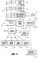
- Figure 1 provides a block diagram illustrating operation of a system or method for controlling engine torque according to the present invention.
- System 10 includes a vehicular powertrain 12 having an internal combustion engine 14 coupled to an automatic transmission 16.
- Powertrain 12 may also include a controller 18 in communication with engine 14 and transmission 16 for providing various information and control functions.
- Engine 14 is connected to transmission 16 via crankshaft 20 which is connected to transmission pump 22 and/or torque converter 24.
- torque converter 24 is a hydrodynamic torque converter including a pump or impeller 26 which is selectively fluidly coupled to a turbine 28.
- Torque converter 24 may also include a frictional converter clutch or bypass clutch 30 which provides a selective frictional coupling between turbine shaft 32 and input shaft 34.
- Automatic transmission 16 includes a plurality of input-to-output ratios or gear ratios effected by various gears, indicated generally by reference numeral 36, and associated frictional elements such as clutches, bands, and the like, as well known in the art.
- Gears 36 provide selective reduction or multiplication ratios between turbine shaft 32 and output shaft 38.
- Automatic transmission 16 is preferably electronically controlled via one or more shift solenoids, indicated generally by reference numeral 40, and a converter clutch control (CC) 41 to select an appropriate gear ratio based on current operating conditions.
- Transmission 16 also preferably includes an actuator for controlling pump pressure (PP) 42 (or line pressure), in addition to a shift lever position sensor (PRN) 44 to provide an indication of the operator's selected gear or driving mode, such as drive, reverse, park, etc.
- a line pressure sensor (LP) 46 can be provided to facilitate closed loop feedback control of the hydraulic line pressure during shifting or ratio changing.
- output shaft 38 may be coupled to one or more axles 48 via a final drive reduction or differential 50 which may include one or more gears, as indicated generally by reference numeral 52.
- Each axle 48 may include two or more wheels 54 having corresponding wheel speed sensors 56.
- powertrain 12 preferably includes a plurality of sensors, indicated generally by reference numeral 60, in communication with corresponding input ports 62 of controller 18 to sense or monitor the current operating and ambient conditions of powertrain 12.
- the sensors preferably include a throttle valve position sensor (TPS) 68 which monitors the position of throttle valve 70 which is disposed within intake 72.
- TPS throttle valve position sensor
- a mass airflow sensor (MAF) 74 provides an indication of the air mass flowing through intake 72.
- a temperature sensor (TMP) 76 provides an indication of the engine temperature which may include engine coolant temperature or engine oil temperature, for example.
- an engine speed sensor (RPM) 80 monitors rotational speed of crankshaft 20.
- a turbine speed sensor 82 monitors the rotational speed of the turbine 28 of torque converter 24.
- Another rotational speed sensor, vehicle speed sensor (VSS) 84 provides an indication of the speed of output shaft 38 which may be used to determine the vehicle speed based on the ratio of differential 50 and the size of wheels 54.
- wheel speed sensors (WS1 and WS2) 56 may be used to provide an indication of the vehicle speed as well.
- various sensors may be omitted or alternative sensors provided which generate signals indicative of related sensed parameters. Values corresponding to ambient or operating conditions may be inferred or calculated using one or more of the sensed parameters without departing from the spirit or scope of the present invention.
- An accelerator pedal 58 is manipulated by the driver to control the output of powertrain 12.
- a pedal position sensor 59 provides an indication of the position of accelerator pedal 58, preferably in the form of counts. In one embodiment, an increasing number of counts indicates a request for increased power output. Preferably, redundant position sensors are used with at least one position sensor having a negative slope such that a decreasing number of counts corresponds to a request for increased power output.
- a manifold absolute pressure (MAP) sensor, or equivalent, may be used to provide an indication of the current barometric pressure.
- Actuators 64 are used to provide control signals or to effect movement of various devices in powertrain 12. Actuators 64 may include actuators for timing and metering fuel (FUEL) 90, controlling ignition angle or timing (SPK) 92, controlling intake/exhaust valve actuators 93 (VCT) to implement variable cam timing ,setting the amount of exhaust gas recirculation (EGR) 94, and adjusting the intake air using throttle valve 70 with an appropriate servomotor or actuator (TVA) 96.
- FUEL timing and metering fuel
- SPK ignition angle or timing
- VCT intake/exhaust valve actuators 93
- EGR exhaust gas recirculation
- TVA servomotor or actuator
- automatic transmission 16 may be selectively controlled by controlling transmission pump or line pressure using an appropriate actuator (PP) 42 in combination with shift solenoids (SS1 and SS2) 40 which are used to select an appropriate gear ratio, and a converter clutch actuator or solenoid (CC) 41 used to lock, unlock or control slip of the torque converter clutch 30.
- a temperature sensor 106 is provided to determine the transmission oil temperature (TOT).
- Controller 18 is preferably a microprocessor-based controller which provides integrated control of engine 14 and transmission 16 of powertrain 12. Of course, the present invention may be implemented in a separate engine or transmission controller depending upon the particular application. Controller 18 includes a microprocessor 110 in communication with input ports 62, output ports 66, and computer readable media 112 via a data/control bus 114. Computer readable media 112 may include various types of volatile and non-volatile memory such as random access memory (RAM) 116, read-only memory (ROM) 118, and keep-alive memory (KAM) 119.
- RAM random access memory
- ROM read-only memory
- KAM keep-alive memory
- Computer readable media 112 include stored data representing instructions executable by microprocessor 110 to implement the method for controlling engine torque according to the present invention.
- Figure 2 provides a block diagram of a representative control architecture for use with a system and method for engine control according to the present invention.
- one of the advantages of the present invention is its adaptability and robustness to various control architectures and engine technologies.
- the present invention may be utilised in any of a number of applications and is independent of the particular strategy illustrated for determining a desired engine brake torque and for effecting a requested engine brake torque.
- a driver demand is interpreted as represented by block 120 of Figure 2 based on the vehicle speed 122 accelerator pedal position 124 and barometric pressure 126.
- the driver demand is interpreted as a wheel torque (TQWH_DD) and is provided as an input to block 130 which arbitrates the final wheel torque among various other torque requesters, indicated generally by reference numeral 132.
- torque requesters may include, for example, a cruise control torque 134, a traction assist torque 136, and/or a vehicle speed limiting torque 138.
- Block 130 selects the appropriate torque depending upon the current operating conditions and provides this final wheel torque (TQ_WHEEL) to block 140 which performs a number of functions including scheduling the gear ratio and ratio changes.
- Block 140 preferably includes determination of a torque converter slip, and calculation of a desired engine brake torque based on the final desired wheel torque. Inputs used in these determinations include vehicle speed 122, barometric pressure 126, current gear ratio 142, current torque converter slip 144, and bypass clutch duty cycle 145. Determination of the desired engine torque is explained in greater detail below.
- the engine torque requested from block 140 is arbitrated with various other engine torque limiting functions 146 as represented by block 150.
- Transmission controller 152 may also request torque limiting or modulation to provide cancellation of the inertia phase to improve shift feel.
- Transmission controller 152 communicates with transmission solenoid control module 154 which energises the appropriate shift solenoids to effect the ratio change. Solenoid control module 154 preferably dynamically controls the line pressure via transmission pump pressure actuator 42 during a ratio change to improve shift feel. Alternatively, the apply and release pressures for individual clutches or shifting elements may be controlled during the ratio change to further improve shift feel.
- Transmission controller 152 is also in communication with bypass clutch controller 155 which controls the duty cycle of the torque converter bypass clutch to control the state of the clutch.
- the final engine torque determined by block 150 is communicated as a desired engine brake torque to engine controller 156, illustrated and described in greater detail with reference to Figure 3.
- the engine controller modifies the desired engine brake torque based on current engine operating conditions to determine a requested engine brake torque prior to determination of control parameters such as air flow, spark, EGR, and fuel as represented by blocks 158, 160, 162, and 164, respectively.
- control parameters such as air flow, spark, EGR, and fuel as represented by blocks 158, 160, 162, and 164, respectively.
- control parameters such as air flow, spark, EGR, and fuel as represented by blocks 158, 160, 162, and 164, respectively.
- Various other control parameters may also be used, such as air/fuel ratio, and the like, depending upon the particular application.
- the present invention is described with reference to a system based on desired wheel torque, the present invention is independent of the particular strategy used to determine the desired engine brake torque.
- the present invention could be easily applied to a system which uses a desired tractive effort or wheel power to determine a desired engine brake torque.
- the present invention is applicable to systems which determine a desired engine brake torque directly from the operator via an accelerator pedal or similar device.
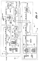
- FIG. 3 is a block diagram illustrating an engine torque controller 156 according to the present invention.
- Engine torque controller 156 includes three functional sections represented generally by reference numerals 200, 202, and 204.
- Block 200 receives a desired engine brake torque (TQ_ENG) and adjusts the desired engine brake torque to generate a requested engine brake torque (TQ_SUM2) based on current operating conditions.
- the requested engine brake torque is provided to block 202 which controls at least one operating parameter of the engine based on the requested engine brake torque to deliver the desired engine brake torque.
- Block 204 includes an airflow-based idle speed controller which generates an idle speed torque determined at least in part based on a desired engine speed, preferably stored in a lookup table.
- Idle speed controller 204 determines the required airflow to provide idle speed control and dashpot modes of operation. As known in the art, dashpot mode operates to modify the engine deceleration rate to smoothly approach the desired idle speed when the accelerator pedal is released. Idle speed controller 204 includes a feed forward idle speed control 206 having various inputs including a desired engine idle speed (N_BASE), engine coolant temperature (ECT), air charge temperature (ACT), and flags or switches to determine the state of various accessories such as air conditioning (A/C) and power steering (P/S).
- N_BASE desired engine idle speed
- ECT engine coolant temperature
- ACT air charge temperature
- flags or switches to determine the state of various accessories such as air conditioning (A/C) and power steering (P/S).
- PID and adaptive control feedback block 208 generates an appropriate output based on an RPM error which is combined with the output from block 206 and a dashpot input to determine a desired airflow (DESMAF). This value is provided to section 202 as explained in greater detail below.
- the desired airflow is also used to generate a torque trim term to provide smooth transitions between idle speed control and other operation modes.
- the torque trim term is produced by generating an airflow error which is operated on by PID controller 210 to reduce the error toward zero.
- the airflow value is converted to a torque trim value by block 212 which is then combined with the desired engine brake torque value at summing junction 214.
- TQ_ENG desired engine brake torque
- TQ_TRIM idle speed torque
- the actual engine brake torque may be an estimated or a measured value for actual torque.
- the second intermediate torque or torque error is provided to a PID controller 220 which generates a feedback correction torque based on the second intermediate torque.
- controller 220 includes proportional, integral, and derivative terms but is not active during certain transient torque limiting control modes, which may include idle speed control, dashpot, engine speed limiting, traction asist, transmission gear shifting, and fail safe cooling, among others.
- controller 220 sets the proportional and derivative terms to zero while holding the integral term constant during these control modes.
- the integral term of controller 220 may be reset during transient torque control modes while setting the proportional and derivative terms to zero.
- the torque feedback controller is preferably deactivated during these transient modes to prevent interference between the control parameters for air and fuel flow and the transient torque control parameters such as spark retard or injector/cylinder cutout.
- An example of a method for reducing engine torque through co-ordinated control of spark retard, cylinder cutout, and air/fuel scheduling can be seen in U.S. Patent No. 5,479,898, for example.
- Block 216 preferably provides an estimate of the actual engine brake torque based on current engine operating parameters including ignition angle, air/fuel ratio, number of cylinders, variable CAM timing angle, engine coolant temperature, engine speed, airflow, and operation state of accessories such as the air conditioning compressor.
- current engine operating parameters including ignition angle, air/fuel ratio, number of cylinders, variable CAM timing angle, engine coolant temperature, engine speed, airflow, and operation state of accessories such as the air conditioning compressor.
- various other parameters may be included in determining the actual engine brake torque.
- an appropriate sensor may be provided to directly determine the actual engine brake torque. Determination of an estimated actual torque is described in greater detail in U.S. Patent No. 5,241,855, assigned to the Assignee of the present invention.
- TQ_PID The feedback correction torque generated by PID controller 220
- ETC_TQ_LOSS a third intermediate torque
- the third intermediate torque may represent an accessory brake torque and/or the additional torque required to overcome increased frictional losses during cold engine operation.
- the third intermediate torque is the sum of the estimated accessory brake torques including the air conditioning compressor, front end accessory friction, power steering pump losses, and additional rotational friction attributable to cold engine operation.
- the output of block 222 is then the requested final engine brake torque which is provided to section 202 to control the engine output.
- section 202 uses airflow as the primary control parameter.
- fuel delivery or fuel flow may also be controlled to control the engine output torque.
- the input to the torque controller section 202 is compensated to request additional torque to compensate for accessory losses and cold friction losses as opposed to modifying the output of the torque controller as seen in various prior art references.
- the present invention is independent of the particular strategy or controller used to deliver the requested engine brake torque.
- airflow is used as the primary control parameter to deliver the requested torque for stoichiometric operation.
- Various other operational modes and/or engine technologies such as lean burn, may utilise airflow control, fuel flow control, spark or ignition angle control, and the like as well known in the art.
- block 230 which provides feed forward compensation to compensate for the non-linear effects of the air/fuel ratio being rich or lean of stoichiometry, i.e., an air/fuel ratio between about 12:1 and about 18:1.
- block 230 compensates for the non-linear effects of the spark or ignition angle being retarded from the steady-state operation conditions, such as when in idle speed control mode. This is considered a feed forward compensation because these terms modify the control input to cause total or partial cancellation of the non-linear functions of the model.
- Improved transient and steady-state control is provided by combining the feed forward compensation of block 230 with the feedback operation of block 220.
- Block 230 includes inputs representing the operating air/fuel equivalence ratio (LAMBSE), spark retard from MBT (SPK_DELTA), engine speed (RPM), and load.
- LAMBSE operating air/fuel equivalence ratio
- SPK_DELTA spark retard from MBT
- RPM engine speed
- TQ_ENG_DES the input torque to block 230
- TQ_ENG_TOT TQ_ENG_DES TQ_RATIO LAMBSE*TQ_RATIO_SPK
- the output of block 230 (TQ_ENG_TOT) is provided to block 232 which converts the torque to a required airflow (load) to achieve the requested value of engine brake torque.
- this model (FNTQETC) is in the form of a lookup table referenced by requested engine brake torque and engine speed. In one embodiment, this model assumes minimal accessory losses, stoichiometric operation, warm engine operation, and standard temperature and pressure calibrations.
- Block 236 operates as a multiplexer or switch to switch between the real-time controller and the idle speed or dashpot mode control. The appropriate input is selected and passed to the output based on the APP (at part pedal) flag which is set to zero or one when the accelerator pedal is either partly depressed or fully depressed and equal to minus one when the accelerator pedal is not depressed.
- APP at part pedal
- Block 238 selects the higher value for the airflow from the idle speed controller or the real-time engine torque controller to ensure that the final requested airflow (ETC_DESMAF) does not decrease below the idle speed control setting (DESMAF) due to any modelling errors in the torque-to-load table (FNTQETC) represented by block 232. As such, block 238 always selects the maximum of its two inputs which is then provided at the output.
- FIG. 4 a flowchart illustrating control logic of one embodiment of a system or method according to the present invention is shown.
- the flowchart illustrated in Figure 4 may represent any of a number of known processing strategies such as event-driven, interrupt-driven, multi-tasking, multi-threading, and the like. As such, various steps or functions illustrated may be performed in the sequence illustrated, in parallel, or in some cases omitted. Likewise, the order of processing is not necessarily required to achieve the objects, features, and advantages of the invention, but is provided for ease of illustration and description.
- the control logic is implemented in software which is executed by a microprocessor-based controller. Of course, the control logic may be implemented in software, hardware, or a combination of software and hardware.
- the flowchart of Figures 4 illustrate one "loop" and its operations are preferably repeated at predetermined time intervals as known by those of skill in the art.
- Block 300 represents determining a desired engine brake torque.
- various techniques may be used to determine the desired engine brake torque.
- the desired engine brake torque is determined based on the vehicle speed, accelerator pedal position, and current barometric pressure.
- a driver demanded torque may be represented by a wheel torque, wheel power, engine power, or various other parameters which are converted to a desired engine brake torque.
- Blocks 302-308 adjust the desired engine brake torque to generate a requested engine brake torque based on current operating conditions.
- Blocks 310-312 represent controlling at least one of the operating parameters of the engine based on the requested engine brake torque to deliver the desired engine brake torque.
- block 302 represents combining the desired engine brake torque with an idle speed torque to generate a first intermediate torque.
- the idle speed torque is a torque trim value which is used to provide smooth transitions between the idle speed controller and the engine torque controller.
- the first intermediate torque is compared to the actual engine brake torque to generate a second intermediate torque as represented by block 304.
- the first intermediate torque is also used in a feed forward arrangement as illustrated in Figure 3 and represented by block 308.
- Block 306 represents generating a feedback correction torque based on the second intermediate torque.
- a proportional-integral-derivative (PID) controller is used to generate the feedback correction torque.
- the proportional and derivative terms are set to zero while the integral term is held constant during at least one engine control mode where transient torque control is necessary, such as during idle speed control, traction assist, and the like.
- the output of the feedback correction torque block is used to adjust the requested engine brake torque to drive the torque error toward zero.
- a third intermediate torque based on accessory loads and/or engine frictional losses is determined as represented by block 308.
- block 308 represents determination of an estimated accessory brake torque which includes the torque required to operate various vehicle accessories including an air conditioning compressor, power steering pump, and the like.
- Various losses may also be compensated for by block 308 including the frictional losses.
- frictional losses generally vary as a function of engine temperature and engine speed.
- block 308 preferably includes a term for frictional losses based on engine temperature and engine speed.
- the first intermediate torque, feedback correction torque, and third intermediate torque are combined to determine the requested engine brake torque as represented by block 310.
- the requested engine brake torque is then compensated for the torque reducing effects of spark retard and LAMBSE being rich or lean of stoichiometry.
- the compensated requested engine brake torque is then provided to block 312 where it is converted to appropriate control parameters to control the engine as represented by block 312.
- the control parameters may include airflow, fuel, ignition angle (spark), CAM timing, and the like, depending upon the particular application.
- the present invention compensates the input to the engine torque controller prior to determination of the control parameters rather than modifying the output of the engine torque controller as described in the prior art.
- This provides a more robust torque controller which is more easily applied to various engine technologies including lean burn, variable CAM timing, and the like.
Landscapes
- Engineering & Computer Science (AREA)
- Chemical & Material Sciences (AREA)
- Combustion & Propulsion (AREA)
- Mechanical Engineering (AREA)
- General Engineering & Computer Science (AREA)
- Theoretical Computer Science (AREA)
- Signal Processing (AREA)
- Combined Controls Of Internal Combustion Engines (AREA)
- Control Of Vehicle Engines Or Engines For Specific Uses (AREA)
- Electrical Control Of Air Or Fuel Supplied To Internal-Combustion Engine (AREA)
Applications Claiming Priority (2)
| Application Number | Priority Date | Filing Date | Title |
|---|---|---|---|
| US09/370,234 US6279531B1 (en) | 1999-08-09 | 1999-08-09 | System and method for controlling engine torque |
| US370234 | 1999-08-09 |
Publications (2)
| Publication Number | Publication Date |
|---|---|
| EP1076165A2 true EP1076165A2 (fr) | 2001-02-14 |
| EP1076165A3 EP1076165A3 (fr) | 2002-04-03 |
Family
ID=23458793
Family Applications (1)
| Application Number | Title | Priority Date | Filing Date |
|---|---|---|---|
| EP00306482A Withdrawn EP1076165A3 (fr) | 1999-08-09 | 2000-07-28 | Méthode et dispositif pour contrôler le couple d'un moteur à combustion interne |
Country Status (2)
| Country | Link |
|---|---|
| US (2) | US6279531B1 (fr) |
| EP (1) | EP1076165A3 (fr) |
Cited By (10)
| Publication number | Priority date | Publication date | Assignee | Title |
|---|---|---|---|---|
| EP1378646A2 (fr) | 2002-07-04 | 2004-01-07 | Calsonic Kansei Corporation | Système de commande de véhicule |
| GB2368143B (en) * | 2000-09-26 | 2004-11-10 | Ford Global Tech Inc | Engine airflow control |
| WO2006040302A1 (fr) * | 2004-10-08 | 2006-04-20 | Robert Bosch Gmbh | Procede et dispositif pour commander une unite d'entrainement |
| EP1308342A3 (fr) * | 2001-11-02 | 2006-05-10 | Ford Global Technologies, Inc. | Détermination de couple pour ensemble transmission à convertisseur de couple |
| FR2940224A1 (fr) * | 2008-12-22 | 2010-06-25 | Renault Sas | Procede de fonctionnement d'un systeme de correction de la trajectoire d'un vehicule automobile |
| EP2096285A3 (fr) * | 2004-08-04 | 2010-12-22 | Toyota Jidosha Kabushiki Kaisha | Méthode d'estimation du couple moteur |
| CN102383947A (zh) * | 2010-08-30 | 2012-03-21 | 通用汽车环球科技运作有限责任公司 | 控制混合动力传动系统中内燃发动机的方法 |
| DE202014008451U1 (de) * | 2014-10-22 | 2016-01-25 | GM Global Technology Operations LLC (n. d. Ges. d. Staates Delaware) | Vorrichtung zum Steuern einer Kraftfahrzeug-Brennkraftmaschine bei unterbrochener Kraftstoffzufuhr |
| CN108730047A (zh) * | 2017-04-13 | 2018-11-02 | 上海汽车集团股份有限公司 | 一种发动机目标扭矩图谱的生成方法及装置 |
| WO2024028053A1 (fr) * | 2022-08-03 | 2024-02-08 | Robert Bosch Gmbh | Procédé de détermination du couple de freinage d'un frein moteur, procédé de détermination d'une valeur cible d'une pression de collecteur d'induction pour obtenir un couple de freinage cible par un frein moteur, unité de calcul et programme informatique |
Families Citing this family (47)
| Publication number | Priority date | Publication date | Assignee | Title |
|---|---|---|---|---|
| JP2002041322A (ja) * | 2000-07-26 | 2002-02-08 | Sumitomo Wiring Syst Ltd | 車載用電子ユニットの検査方法 |
| US6411882B1 (en) * | 2000-12-02 | 2002-06-25 | Ford Global Technologies, Inc. | Drive-by-wire vehicle engine output control system |
| JP2002276447A (ja) * | 2001-03-19 | 2002-09-25 | Denso Corp | 内燃機関の制御装置 |
| EP1537315B1 (fr) * | 2002-09-05 | 2006-07-12 | Bombardier Transportation GmbH | Procede et dispositif pour commander un ensemble moteur |
| AU2003303392A1 (en) * | 2002-12-23 | 2004-07-22 | Jacobs Vehicle Systems, Inc. | Engine braking methods and apparatus |
| US6754578B1 (en) * | 2003-03-27 | 2004-06-22 | Ford Global Technologies, Llc | Computer instructions for control of multi-path exhaust system in an engine |
| US7021289B2 (en) * | 2004-03-19 | 2006-04-04 | Ford Global Technology, Llc | Reducing engine emissions on an engine with electromechanical valves |
| US7107946B2 (en) * | 2004-03-19 | 2006-09-19 | Ford Global Technologies, Llc | Electromechanically actuated valve control for an internal combustion engine |
| US7128043B2 (en) | 2004-03-19 | 2006-10-31 | Ford Global Technologies, Llc | Electromechanically actuated valve control based on a vehicle electrical system |
| US7128687B2 (en) * | 2004-03-19 | 2006-10-31 | Ford Global Technologies, Llc | Electromechanically actuated valve control for an internal combustion engine |
| US7240663B2 (en) * | 2004-03-19 | 2007-07-10 | Ford Global Technologies, Llc | Internal combustion engine shut-down for engine having adjustable valves |
| US7079935B2 (en) * | 2004-03-19 | 2006-07-18 | Ford Global Technologies, Llc | Valve control for an engine with electromechanically actuated valves |
| US7165391B2 (en) * | 2004-03-19 | 2007-01-23 | Ford Global Technologies, Llc | Method to reduce engine emissions for an engine capable of multi-stroke operation and having a catalyst |
| US7140355B2 (en) * | 2004-03-19 | 2006-11-28 | Ford Global Technologies, Llc | Valve control to reduce modal frequencies that may cause vibration |
| US7194993B2 (en) | 2004-03-19 | 2007-03-27 | Ford Global Technologies, Llc | Starting an engine with valves that may be deactivated |
| US7063062B2 (en) * | 2004-03-19 | 2006-06-20 | Ford Global Technologies, Llc | Valve selection for an engine operating in a multi-stroke cylinder mode |
| US7559309B2 (en) | 2004-03-19 | 2009-07-14 | Ford Global Technologies, Llc | Method to start electromechanical valves on an internal combustion engine |
| US7555896B2 (en) | 2004-03-19 | 2009-07-07 | Ford Global Technologies, Llc | Cylinder deactivation for an internal combustion engine |
| US7066121B2 (en) * | 2004-03-19 | 2006-06-27 | Ford Global Technologies, Llc | Cylinder and valve mode control for an engine with valves that may be deactivated |
| US7072758B2 (en) | 2004-03-19 | 2006-07-04 | Ford Global Technologies, Llc | Method of torque control for an engine with valves that may be deactivated |
| US7383820B2 (en) | 2004-03-19 | 2008-06-10 | Ford Global Technologies, Llc | Electromechanical valve timing during a start |
| US7448983B2 (en) * | 2004-06-07 | 2008-11-11 | Ford Global Technologies, Llc | System and method for utilizing estimated driver braking effort |
| US20060047400A1 (en) * | 2004-08-25 | 2006-03-02 | Raj Prakash | Method and apparatus for braking and stopping vehicles having an electric drive |
| US7144779B2 (en) * | 2004-09-01 | 2006-12-05 | Micron Technology, Inc. | Method of forming epitaxial silicon-comprising material |
| US7630811B2 (en) * | 2005-01-18 | 2009-12-08 | Ford Global Technologies, Llc | Automated manual transmission launch control |
| ITBO20050025A1 (it) * | 2005-01-19 | 2006-07-20 | Magneti Marelli Powertrain Spa | Metodo e dispositivo di gestione della crociera di un veicolo stradale |
| US7544150B2 (en) * | 2005-05-23 | 2009-06-09 | Gm Global Technology Operations, Inc. | Engine torque error learn during dynamic vehicle test |
| US7543670B2 (en) * | 2005-10-31 | 2009-06-09 | Gm Global Technology Operations, Inc. | Wheel slip control system |
| US7275518B1 (en) | 2006-04-28 | 2007-10-02 | Ford Global Technologies, Llc | Torque-based powertrain control for vehicles |
| CN101484677B (zh) * | 2006-07-13 | 2012-10-10 | 沃尔沃拉斯特瓦格纳公司 | 用于操作内燃发动机制动器的方法和系统 |
| DE102006061438A1 (de) * | 2006-12-23 | 2008-06-26 | Dr.Ing.H.C. F. Porsche Ag | Verfahren und Steuergerät zur Überprüfung einer Saugrohrlängenverstellung bei einem Verbrennungsmotor |
| KR100941714B1 (ko) * | 2007-11-07 | 2010-02-12 | 현대자동차주식회사 | 엔진의 토크 제어장치 및 방법 |
| DE102007057786B4 (de) * | 2007-11-30 | 2017-09-07 | Audi Ag | Verfahren zum Betreiben einer Antriebsvorrichtung |
| US7698049B2 (en) * | 2008-01-09 | 2010-04-13 | Gm Global Technology Operations, Inc. | Speed control in a torque-based system |
| DE102008006708B3 (de) * | 2008-01-30 | 2009-08-20 | Mtu Friedrichshafen Gmbh | Verfahren zur Regelung eines stationären Gasmotors |
| JP4702429B2 (ja) * | 2008-10-16 | 2011-06-15 | トヨタ自動車株式会社 | 駆動源の制御装置 |
| WO2010113297A1 (fr) * | 2009-04-01 | 2010-10-07 | トヨタ自動車株式会社 | Appareil de commande de moteur à combustion interne |
| US8744716B2 (en) * | 2009-12-16 | 2014-06-03 | GM Global Technology Operations LLC | Speed control systems and methods for internal combustion engines |
| US8602001B2 (en) * | 2010-09-17 | 2013-12-10 | GM Global Technology Operations LLC | Torque limiting engine lubrication protection system |
| GB2487433A (en) * | 2011-01-24 | 2012-07-25 | Gm Global Tech Operations Inc | An engine control method which alters a fuel request value |
| US9200587B2 (en) * | 2012-04-27 | 2015-12-01 | Tula Technology, Inc. | Look-up table based skip fire engine control |
| US20140163839A1 (en) * | 2012-12-12 | 2014-06-12 | GM Global Technology Operations LLC | Systems and methods for controlling cylinder deactivation and accessory drive tensioner arm motion |
| US9353655B2 (en) | 2013-03-08 | 2016-05-31 | GM Global Technology Operations LLC | Oil pump control systems and methods for noise minimization |
| US9732722B1 (en) * | 2015-03-06 | 2017-08-15 | Brunswick Corporation | Methods and systems for cylinder speed increase control to improve combustion uniformity |
| CN107203184B (zh) * | 2017-06-20 | 2019-04-16 | 南京理工大学 | 直线舵机电动加载系统的动态控制方法 |
| CN111828191B (zh) * | 2020-03-24 | 2021-10-08 | 同济大学 | 一种混合动力发动机的空燃比控制系统及方法 |
| CN120968927B (zh) * | 2025-10-17 | 2026-01-23 | 潍柴动力股份有限公司 | 发动机转速控制方法、装置、计算机设备及存储介质 |
Citations (5)
| Publication number | Priority date | Publication date | Assignee | Title |
|---|---|---|---|---|
| US5241855A (en) | 1991-10-31 | 1993-09-07 | Ford Motor Company | Method and apparatus for inferring engine torque |
| US5351776A (en) | 1991-04-05 | 1994-10-04 | Robert Bosch Gmbh | Electronic system for a motor vehicle |
| US5383432A (en) | 1993-07-06 | 1995-01-24 | Ford Motor Company | Method and apparatus for controlling ignition timing based on fuel-air composition during fuel excursions |
| US5479898A (en) | 1994-07-05 | 1996-01-02 | Ford Motor Company | Method and apparatus for controlling engine torque |
| US5501989A (en) | 1993-03-22 | 1996-03-26 | Semiconductor Energy Laboratory Co., Ltd. | Method of making semiconductor device/circuit having at least partially crystallized semiconductor layer |
Family Cites Families (52)
| Publication number | Priority date | Publication date | Assignee | Title |
|---|---|---|---|---|
| DE2811574A1 (de) | 1978-03-17 | 1979-09-27 | Bosch Gmbh Robert | Vorrichtung zur regelung einer antriebsmotor-getriebe-einheit eines kraftfahrzeuges |
| JPS56107925A (en) | 1980-01-31 | 1981-08-27 | Mikuni Kogyo Co Ltd | Electronically controlled fuel injector for ignited internal combustion engine |
| JPS6034563A (ja) | 1983-08-05 | 1985-02-22 | Nippon Soken Inc | 自動車用自動変速制御装置 |
| JPS60164632A (ja) | 1984-02-07 | 1985-08-27 | Nissan Motor Co Ltd | 自動車の電子制御装置 |
| US4697561A (en) | 1985-04-15 | 1987-10-06 | Purdue Research Foundation | On-line engine torque and torque fluctuation measurement for engine control utilizing crankshaft speed fluctuations |
| US4730708A (en) | 1985-05-30 | 1988-03-15 | Toyota Jidosha Kabushiki Kaisha | Idling control method and system for internal combustion engine providing anti creep action |
| US4760823A (en) | 1985-06-24 | 1988-08-02 | Honda Giken Kogyo Kabushiki Kaisha | Method for control of idle rotations of internal combustion engine |
| US4893526A (en) * | 1986-09-19 | 1990-01-16 | Toyota Jidosha Kabushiki Kaisha | Continuous variable transmission control system |
| JPH0792141B2 (ja) | 1988-05-06 | 1995-10-09 | 日産自動車株式会社 | 自動変速機のライン圧制御装置 |
| JPH0281939A (ja) | 1988-09-16 | 1990-03-22 | Mazda Motor Corp | 自動変速機付車両におけるエンジンの吸入空気量制御装置 |
| JPH0660678B2 (ja) | 1988-10-29 | 1994-08-10 | マツダ株式会社 | 自動変速機のライン圧制御装置 |
| JPH02149738A (ja) * | 1988-12-01 | 1990-06-08 | Mitsubishi Motors Corp | 車両のエンジン出力制御方法 |
| WO1990008888A1 (fr) | 1989-01-31 | 1990-08-09 | Mitsubishi Jidosha Kogyo Kabushiki Kaisha | Commande de puissance de moteurs |
| US5069181A (en) | 1989-01-31 | 1991-12-03 | Mitsubishi Jidosha Kogyo Kabushiki Kaisha | Output control apparatus for an internal combustion engine |
| US5078109A (en) | 1989-01-31 | 1992-01-07 | Mitsubishi Jidosha Kogyo Kabushiki Kaisha | Engine output controlling method |
| JP2510304B2 (ja) | 1989-12-15 | 1996-06-26 | 日産自動車株式会社 | 自動変速機の作動油圧制御装置 |
| JP2510305B2 (ja) | 1989-12-19 | 1996-06-26 | 日産自動車株式会社 | 自動変速機の作動油圧制御装置 |
| DE4037237A1 (de) | 1990-11-23 | 1992-05-27 | Bosch Gmbh Robert | Verfahren zum betreiben einer aus brennkraftmaschine und automatischem getriebe bestehenden antriebseinheit |
| US5304102A (en) | 1991-02-21 | 1994-04-19 | Nissan Motor Co., Ltd. | Control for shift in automatic transmission |
| DE4210956A1 (de) | 1991-08-02 | 1993-02-04 | Bosch Gmbh Robert | Einrichtung zur steuerung der ausgangsleistung einer antriebseinheit eines fahrzeugs |
| DE4141947C2 (de) * | 1991-12-19 | 2002-02-07 | Bosch Gmbh Robert | Steuersystem für eine Antriebseinheit in einem Flugzeug |
| DE4204401A1 (de) | 1992-02-14 | 1993-08-19 | Bosch Gmbh Robert | Einrichtung zur steuerung des abtriebsmoments eines automatischen schaltgetriebes |
| DE4304779B4 (de) | 1992-06-20 | 2005-11-24 | Robert Bosch Gmbh | Vorrichtung zur Steuerung des von einer Antriebseinheit eines Fahrzeugs abzugebenden Drehmoments |
| US5253623A (en) * | 1992-08-10 | 1993-10-19 | Ford Motor Company | Method of controlling combustion engine timing |
| EP0715099B1 (fr) | 1992-09-16 | 1999-12-29 | Hitachi, Ltd. | Système de commande de la force d'entraínement d'un véhicule |
| DE4235827B4 (de) | 1992-10-23 | 2013-05-08 | Robert Bosch Gmbh | Verfahren und Einrichtung zur Steuerung der Ausgangsleistung einer Antriebseinheit eines Fahrzeugs |
| DE4311921A1 (de) | 1993-04-10 | 1994-10-13 | Bosch Gmbh Robert | Verfahren zur Betätigung eines automatischen Getriebes |
| CZ320995A3 (en) | 1993-06-30 | 1996-05-15 | Orbital Eng Pty | Method of controlling air supply into an internal combustion engine and apparatus for making the same |
| DE4329978A1 (de) | 1993-09-04 | 1995-03-09 | Bosch Gmbh Robert | Verfahren und Vorrichtung zur Betätigung eines selbständig schaltenden Getriebes |
| DE4333899A1 (de) | 1993-10-05 | 1995-07-13 | Bosch Gmbh Robert | Verfahren zur Steuerung des Abtriebsmoments eines automatischen Schaltgetriebes |
| DE4343353C2 (de) | 1993-12-18 | 2002-12-05 | Bosch Gmbh Robert | Verfahren und Vorrichtung zum Steuern einer Brennkraftmaschine |
| US5408974A (en) | 1993-12-23 | 1995-04-25 | Ford Motor Company | Cylinder mode selection system for variable displacement internal combustion engine |
| US5398544A (en) | 1993-12-23 | 1995-03-21 | Ford Motor Company | Method and system for determining cylinder air charge for variable displacement internal combustion engine |
| US5374224A (en) | 1993-12-23 | 1994-12-20 | Ford Motor Company | System and method for controlling the transient torque output of a variable displacement internal combustion engine |
| US5431139A (en) | 1993-12-23 | 1995-07-11 | Ford Motor Company | Air induction control system for variable displacement internal combustion engine |
| US5408966A (en) | 1993-12-23 | 1995-04-25 | Ford Motor Company | System and method for synchronously activating cylinders within a variable displacement engine |
| DE4407475C2 (de) | 1994-03-07 | 2002-11-14 | Bosch Gmbh Robert | Verfahren und Vorrichtung zur Steuerung eines Fahrzeugs |
| US5445125A (en) | 1994-03-16 | 1995-08-29 | General Motors Corporation | Electronic throttle control interface |
| US5520159A (en) | 1994-12-09 | 1996-05-28 | Ford Motor Company | Burned gas recycling system with powertrain optimization |
| DE19502150C1 (de) | 1995-01-25 | 1996-05-23 | Bosch Gmbh Robert | System zur Regelung der Aufladung einer Brennkraftmaschine |
| JP3573368B2 (ja) | 1995-02-21 | 2004-10-06 | 本田技研工業株式会社 | 車両のエンジン出力制御装置 |
| DE19517434B4 (de) | 1995-05-12 | 2006-08-10 | Robert Bosch Gmbh | Verfahren zur Unterbrechung der Kraftstoffzufuhr im Schiebebetrieb einer Brennkraftmaschine |
| US5503129A (en) | 1995-05-18 | 1996-04-02 | Ford Motor Company | Apparatus and method for mode recommendation in a variable displacement engine |
| US5568795A (en) | 1995-05-18 | 1996-10-29 | Ford Motor Company | System and method for mode selection in a variable displacement engine |
| US5588178A (en) | 1995-06-07 | 1996-12-31 | Mcculloch Corporation | Impeller for blower/vacuum |
| GB2312970A (en) | 1996-05-11 | 1997-11-12 | Ford Motor Co | Diesel engine control |
| DE19704153C2 (de) * | 1997-02-04 | 2000-10-19 | Isad Electronic Sys Gmbh & Co | Antriebssystem, insbesondere für ein Kraftfahrzeug und Verfahren zum Entgegenwirken einer Änderung der Leerlaufdrehzahl in einem Antriebssystem |
| EP1469178A3 (fr) * | 1997-05-26 | 2005-06-08 | Nissan Motor Co., Ltd. | Régulateur de vitesse de ralenti d'un moteur à combustion interne |
| JP3514077B2 (ja) * | 1997-06-24 | 2004-03-31 | 日産自動車株式会社 | エンジンのスロットル制御装置 |
| DE19733106A1 (de) * | 1997-07-31 | 1999-02-04 | Siemens Ag | Verfahren zum Steuern einer Brennkraftmaschine |
| DE19803387C1 (de) * | 1998-01-29 | 1999-03-18 | Daimler Benz Ag | Verfahren zur Einstellung der Ausgangsleistung einer Brennkraftmaschine |
| US6219611B1 (en) * | 1999-10-18 | 2001-04-17 | Ford Global Technologies, Inc. | Control method for engine having multiple control devices |
-
1999
- 1999-08-09 US US09/370,234 patent/US6279531B1/en not_active Expired - Lifetime
-
2000
- 2000-07-28 EP EP00306482A patent/EP1076165A3/fr not_active Withdrawn
-
2001
- 2001-06-25 US US09/891,488 patent/US6401026B2/en not_active Expired - Lifetime
Patent Citations (5)
| Publication number | Priority date | Publication date | Assignee | Title |
|---|---|---|---|---|
| US5351776A (en) | 1991-04-05 | 1994-10-04 | Robert Bosch Gmbh | Electronic system for a motor vehicle |
| US5241855A (en) | 1991-10-31 | 1993-09-07 | Ford Motor Company | Method and apparatus for inferring engine torque |
| US5501989A (en) | 1993-03-22 | 1996-03-26 | Semiconductor Energy Laboratory Co., Ltd. | Method of making semiconductor device/circuit having at least partially crystallized semiconductor layer |
| US5383432A (en) | 1993-07-06 | 1995-01-24 | Ford Motor Company | Method and apparatus for controlling ignition timing based on fuel-air composition during fuel excursions |
| US5479898A (en) | 1994-07-05 | 1996-01-02 | Ford Motor Company | Method and apparatus for controlling engine torque |
Cited By (15)
| Publication number | Priority date | Publication date | Assignee | Title |
|---|---|---|---|---|
| GB2368143B (en) * | 2000-09-26 | 2004-11-10 | Ford Global Tech Inc | Engine airflow control |
| EP1308342A3 (fr) * | 2001-11-02 | 2006-05-10 | Ford Global Technologies, Inc. | Détermination de couple pour ensemble transmission à convertisseur de couple |
| EP1378646A3 (fr) * | 2002-07-04 | 2007-09-26 | Calsonic Kansei Corporation | Système de commande de véhicule |
| EP1378646A2 (fr) | 2002-07-04 | 2004-01-07 | Calsonic Kansei Corporation | Système de commande de véhicule |
| EP2096287A3 (fr) * | 2004-08-04 | 2011-01-19 | Toyota Jidosha Kabushiki Kaisha | Méthode d'estimation du couple moteur |
| EP2096285A3 (fr) * | 2004-08-04 | 2010-12-22 | Toyota Jidosha Kabushiki Kaisha | Méthode d'estimation du couple moteur |
| WO2006040302A1 (fr) * | 2004-10-08 | 2006-04-20 | Robert Bosch Gmbh | Procede et dispositif pour commander une unite d'entrainement |
| US7698050B2 (en) | 2004-10-08 | 2010-04-13 | Robert Bosch Gmbh | Method and device for controlling a drive unit |
| FR2940224A1 (fr) * | 2008-12-22 | 2010-06-25 | Renault Sas | Procede de fonctionnement d'un systeme de correction de la trajectoire d'un vehicule automobile |
| CN102383947A (zh) * | 2010-08-30 | 2012-03-21 | 通用汽车环球科技运作有限责任公司 | 控制混合动力传动系统中内燃发动机的方法 |
| CN102383947B (zh) * | 2010-08-30 | 2014-07-16 | 通用汽车环球科技运作有限责任公司 | 控制混合动力传动系统中内燃发动机的方法 |
| DE202014008451U1 (de) * | 2014-10-22 | 2016-01-25 | GM Global Technology Operations LLC (n. d. Ges. d. Staates Delaware) | Vorrichtung zum Steuern einer Kraftfahrzeug-Brennkraftmaschine bei unterbrochener Kraftstoffzufuhr |
| CN108730047A (zh) * | 2017-04-13 | 2018-11-02 | 上海汽车集团股份有限公司 | 一种发动机目标扭矩图谱的生成方法及装置 |
| CN108730047B (zh) * | 2017-04-13 | 2020-07-31 | 上海汽车集团股份有限公司 | 一种发动机目标扭矩图谱的生成方法及装置 |
| WO2024028053A1 (fr) * | 2022-08-03 | 2024-02-08 | Robert Bosch Gmbh | Procédé de détermination du couple de freinage d'un frein moteur, procédé de détermination d'une valeur cible d'une pression de collecteur d'induction pour obtenir un couple de freinage cible par un frein moteur, unité de calcul et programme informatique |
Also Published As
| Publication number | Publication date |
|---|---|
| US20010037793A1 (en) | 2001-11-08 |
| EP1076165A3 (fr) | 2002-04-03 |
| US6279531B1 (en) | 2001-08-28 |
| US6401026B2 (en) | 2002-06-04 |
Similar Documents
| Publication | Publication Date | Title |
|---|---|---|
| US6279531B1 (en) | System and method for controlling engine torque | |
| US6434466B1 (en) | System and method for determining engine torque for controlling a powertrain | |
| EP1074717B1 (fr) | Système et méthode pour déterminer les parametres de controle d'un moteur à partir du couple | |
| US6701246B2 (en) | Engine torque determination for powertrain with torque converter | |
| US6220987B1 (en) | Automatic transmission ratio change schedules based on desired powertrain output | |
| US6199004B1 (en) | Vehicle and engine control system | |
| EP1186462A2 (fr) | Appareil pour la régulation d'un moteur à combustion et le rapport de vitesse d'une transmission | |
| US20110313628A1 (en) | Control apparatus and control method for drive source | |
| US20110288732A1 (en) | Control apparatus and control method for vehicle | |
| US7425187B2 (en) | System and method for improved fuel economy during vehicle deceleration conditions | |
| US6584392B1 (en) | Powertrain output monitor | |
| US20050016472A1 (en) | Control system for engine cooling | |
| US20100274460A1 (en) | Control apparatus and control method for power source | |
| US6364812B1 (en) | Automatic transmission dynamic electronic pressure control based on desired powertrain output | |
| US7983826B2 (en) | Control apparatus and control method for drive source | |
| GB2380776A (en) | Method of determining engine torque which is used to control a powertrain | |
| US7555368B2 (en) | Synthesized control input | |
| JP4872985B2 (ja) | 駆動源の制御装置 | |
| JP5231948B2 (ja) | エンジンの制御装置および制御方法 | |
| JP5082883B2 (ja) | パワートレーンの制御装置 | |
| CN110630389A (zh) | 一种基于请求的发动机制动转矩确定发动机控制参数的方法 | |
| JP2009250084A (ja) | 駆動源の制御装置 | |
| JP2009250085A (ja) | 駆動源の制御装置 | |
| JP2010121491A (ja) | 駆動源の制御装置 | |
| JP2010096086A (ja) | エンジンの制御装置および制御方法 |
Legal Events
| Date | Code | Title | Description |
|---|---|---|---|
| PUAI | Public reference made under article 153(3) epc to a published international application that has entered the european phase |
Free format text: ORIGINAL CODE: 0009012 |
|
| AK | Designated contracting states |
Kind code of ref document: A2 Designated state(s): AT BE CH CY DE DK ES FI FR GB GR IE IT LI LU MC NL PT SE Kind code of ref document: A2 Designated state(s): DE FR GB |
|
| AX | Request for extension of the european patent |
Free format text: AL;LT;LV;MK;RO;SI |
|
| PUAL | Search report despatched |
Free format text: ORIGINAL CODE: 0009013 |
|
| AK | Designated contracting states |
Kind code of ref document: A3 Designated state(s): AT BE CH CY DE DK ES FI FR GB GR IE IT LI LU MC NL PT SE |
|
| AX | Request for extension of the european patent |
Free format text: AL;LT;LV;MK;RO;SI |
|
| 17P | Request for examination filed |
Effective date: 20020910 |
|
| AKX | Designation fees paid |
Free format text: DE FR GB |
|
| STAA | Information on the status of an ep patent application or granted ep patent |
Free format text: STATUS: THE APPLICATION HAS BEEN WITHDRAWN |
|
| 18W | Application withdrawn |
Effective date: 20041109 |