EP1077533A1 - Terminal numérique mobile et sans fil, et système utilisant un tel terminal - Google Patents
Terminal numérique mobile et sans fil, et système utilisant un tel terminal Download PDFInfo
- Publication number
- EP1077533A1 EP1077533A1 EP00306746A EP00306746A EP1077533A1 EP 1077533 A1 EP1077533 A1 EP 1077533A1 EP 00306746 A EP00306746 A EP 00306746A EP 00306746 A EP00306746 A EP 00306746A EP 1077533 A1 EP1077533 A1 EP 1077533A1
- Authority
- EP
- European Patent Office
- Prior art keywords
- signal
- transmission
- communications
- communications apparatus
- environment
- Prior art date
- Legal status (The legal status is an assumption and is not a legal conclusion. Google has not performed a legal analysis and makes no representation as to the accuracy of the status listed.)
- Withdrawn
Links
Images


Classifications
-
- H—ELECTRICITY
- H04—ELECTRIC COMMUNICATION TECHNIQUE
- H04L—TRANSMISSION OF DIGITAL INFORMATION, e.g. TELEGRAPHIC COMMUNICATION
- H04L1/00—Arrangements for detecting or preventing errors in the information received
- H04L1/20—Arrangements for detecting or preventing errors in the information received using signal quality detector
-
- H—ELECTRICITY
- H04—ELECTRIC COMMUNICATION TECHNIQUE
- H04B—TRANSMISSION
- H04B17/00—Monitoring; Testing
- H04B17/30—Monitoring; Testing of propagation channels
- H04B17/309—Measuring or estimating channel quality parameters
- H04B17/318—Received signal strength
-
- H—ELECTRICITY
- H04—ELECTRIC COMMUNICATION TECHNIQUE
- H04B—TRANSMISSION
- H04B17/00—Monitoring; Testing
- H04B17/30—Monitoring; Testing of propagation channels
- H04B17/391—Modelling the propagation channel
-
- H—ELECTRICITY
- H04—ELECTRIC COMMUNICATION TECHNIQUE
- H04B—TRANSMISSION
- H04B7/00—Radio transmission systems, i.e. using radiation field
- H04B7/01—Reducing phase shift
-
- H—ELECTRICITY
- H04—ELECTRIC COMMUNICATION TECHNIQUE
- H04W—WIRELESS COMMUNICATION NETWORKS
- H04W52/00—Power management, e.g. Transmission Power Control [TPC] or power classes
- H04W52/04—Transmission power control [TPC]
- H04W52/18—TPC being performed according to specific parameters
- H04W52/20—TPC being performed according to specific parameters using error rate
-
- H—ELECTRICITY
- H04—ELECTRIC COMMUNICATION TECHNIQUE
- H04L—TRANSMISSION OF DIGITAL INFORMATION, e.g. TELEGRAPHIC COMMUNICATION
- H04L27/00—Modulated-carrier systems
- H04L27/0014—Carrier regulation
- H04L2027/0024—Carrier regulation at the receiver end
- H04L2027/0026—Correction of carrier offset
- H04L2027/0028—Correction of carrier offset at passband only
Definitions
- the present invention relates to a digital-mobile-wireless-communications apparatus and the system using the same.
- a radio-wave-transmission environment changes every moment caused by a multipath fading.
- a transmission quality has been maintained by changing a zone or a transmission channel as needed while a telephone call is in progress.
- the changes of the radio-wave-transmission environment of transmission paths highly depend on the velocity of a mobile phone, the velocity is calculated prior to a changeover, then the changeover is done based on the calculated velocity.
- GPS Global Positioning System
- the received signal is led into radio-frequency-receiving circuit 902 to demodulate, then fed into GPS-signal-processing circuit 903.
- Circuit 903 decodes information on GPS-satellite's orbital position and time information from the demodulated signal to output them to data-processing circuit 904.
- Circuit 904 calculates the current position of mobile phone 900 accurately, and the result is entered to velocity-detecting circuit 905.
- Circuit 905 calculates the velocity of mobile phone 900 based on the current-position information obtained at intervals over time, and outputs the calculated velocity to control circuit 909.
- Control circuit 909 sends a control signal, which is determined according to the magnitude of the velocity, to transmitting and receiving circuit 907, and changes a time period that monitors a transmission channel adjacent to the in-use channel (this time period is hereafter referred to as a monitoring period). If a channel whose radio-wave-transmission environment is better than that of the in-use channel is detected, control circuit 909 changes the transmission channel into the detected channel.
- the accurately calculated velocity of a mobile phone has not been exploited fully.
- This velocity has been previously used for the purpose of changing the monitoring period of the adjacent channel.
- the detected velocity is not directly related to a physical measure representing a radio-wave-transmission environment of transmission paths, evaluating information on the radio-wave-transmission environment could not be obtained accurately.
- the calculated velocity of a mobile phone is not related to a degradation of a bit-error-rate (BER), which is caused by a Doppler shift (Doppler frequency) of carrier frequencies for the mobile phone moving at a high speed.
- BER bit-error-rate
- the calculated velocity of a mobile phone is not related to a receiving-electric-field intensity of the mobile phone. That is, even if the mobile phone is moving at a high speed under the condition with a sufficient receiving-electric-field intensity, in other words, the condition with a favorable radio-wave-transmission environment, a changeover of the monitoring period is unnecessarily performed as is the case that the radio-wave-transmission environment is in a poor condition. Consequently, the transmission is often subjected to a momentary interruption.
- the present invention thus enables to provide a digital-mobile-wireless-communications apparatus with a capability of getting a higher transmission quality.
- the communications apparatus of the present invention operates at a receiver as follows:
- the relation between the receiving-electric-field intensity and its influence on the BER also depends on which digital-modulation scheme is used, and the relation is often explained theoretically or experimentally under a radio-wave-transmission environment chosen as a model. Therefore, if the receiving-electric-field intensity under a modulation scheme can be calculated, the "most probable" BER corresponding to the receiving-electric-field intensity can be also determined by applying data obtained from a radio-wave-transmission environment modeled after a real-world situation.
- the "most probable" has an implication that the modeled-radio-wave-transmission environment from which the data is obtained is not always fit to the actual radio-wave-transmission environment, in the both cases of the evaluations of the Doppler frequency and the receiving-electric-field intensity.
- the communications apparatus of the present invention can estimate the radio-wave-transmission environment for transmission paths more accurate than before.
- the Doppler frequency and the receiving-electric-field intensity of the carrier frequencies for the communications apparatus are computed as two physical measures in the apparatus.
- a most probable radio-wave-transmission environment of the transmission paths is output.
- the communications apparatus can:
- the present invention enables to provide the communications apparatus with a capability of acquiring a higher transmission quality.
- Figs. 1 to 3 are block diagrams of the digital-mobile-wireless-communications apparatus in accordance with a first preferred embodiment of the present invention.
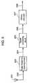
- Fig. 1 is a general block diagram wherein velocity information 101 and receiving signal 106 are fed into a communications apparatus.
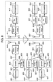
- Fig. 2 and Fig. 3 are sectional block diagrams, showing detail views of velocity-signal generator 102 and receiving-electric-field-intensity-signal generator 107 in Fig. 1, respectively.
- a signal transmitted from GPS-satellites is received by GPS-receiving antenna 201 then sent to radio-frequency-receiving circuit 203 for demodulation.
- Demodulated signal 204 is entered into signal-processing circuit 205.
- Circuit 205 calculates the current position of a communications apparatus based on information on orbital position and time which are transmitted from three or more GPS-satellites, then the calculated current position is fed into velocity calculator 207.
- Calculator 207 calculates the velocity of the communications apparatus according to current-position information obtained at intervals over time, and generates velocity signal 103 to output. This signal, which corresponds to velocity signal 103 in Fig. 1, is entered into Doppler-frequency calculator 104.
- calculator 104 calculates a Doppler frequency (f d ) of the communications apparatus according to the equation described below.
- the calculated result which is output as Doppler-frequency signal 105, is entered into transmission-environment-inference unit 109.
- f d f ⁇ v/V where, "f" represents the carrier frequencies for the communications apparatus, "v” represents the velocity of the communications apparatus, and "V” represents a transmission velocity of radio waves.
- receiving-electric-field-intensity-signal generator 107 in Fig. 1 comprises antenna 301, radio-frequency circuit 303, RSSI detector 305, and receiving-electric-field-intensity calculator 307 shown in Fig. 3.
- Fig. 3 when the communications apparatus and the communications partner are in communication, a radio wave received at antenna 301 is led to radio-frequency circuit 303. After performing amplification and frequency-conversion, circuit 303 generates intermediate-frequency signal 304.
- RSSI detector 305 detects the signal and outputs d. c. voltage 306. Receiving this d. c.
- receiving-electric-field-intensity calculator 307 generates receiving-electric-field-intensity signal 108 to output, which is entered into transmission-environment-inference unit 109 shown in Fig. 1. Since radio-frequency circuit 303 and RSSI detector 305 are so designed as to operate in a linear operation region, d. c. voltage 306 is preferably proportional to the receiving-electric-field intensity.
- the two signals in Fig. 1, i.e., Doppler-frequency signal 105 and receiving-electric-field-intensity signal 108 are entered into transmission-environment-inference means 109 for signal processing.
- a radio wave now-in-use which is subjected to a certain digital-frequency modulation
- a bit-error-rate (BER) vs. receiving-electric-field-intensity characteristics using the carrier frequency shift as a parameter shown in Fig. 4 has been obtained experimentally or theoretically, under a transmission-environment model similar to an actual transmission environment.
- BER bit-error-rate
- curve 401 shows the case of having a larger frequency shift
- curve 402 shows the case of having a smaller frequency shift
- the Doppler frequencies are "fa" and "fb", respectively. It is apparent from Fig. 4 that the larger the frequency shift, the greater the BER. Also, the smaller the receiving-electric-field intensity; the more significant is the difference of curves 401 and 402.
- transmission-environment inference unit 109 In Fig. 1, transmission-environment inference unit 109:
- the transmission-environment-inference signal can be output quantitatively, that is, the transmission environment can be evaluated much more accurate than ever. It is also possible to evaluate the transmission environment by outputting GOOD/BAD evaluating signals in the form of non-numerical values. In this case, two values to be higher and lower thresholds for the BER are set into L1 and L2, respectively. If the computed value mentioned above, namely, the numeral value of transmission-environment-inference signal 110 is larger than L1, the transmission environment is evaluated to be BAD; lies between L1 and L2, the transmission environment is evaluated to be FAIR; and is smaller than L2, the transmission environment is evaluated to be GOOD.
- Fig. 5A shows a mobile-wireless-communications system using a digital-mobile-wireless-communications apparatus in accordance with an exemplary embodiment of the present invention.
- Digital-mobile-wireless-communications apparatus 501 is the same as that explained in the first preferred embodiment.
- apparatus 501 and base station A 502 are in communication now.
- the transmission-environment of the transmission paths is determined to be GOOD by evaluating the transmission-environment-inference signal
- the communication with base station A 502 is continued without a changeover, while if BAD is the result from the evaluation, the communication partner is changed from base station A 502 to base station B 503.
- a desired BER is predetermined as a threshold. That is, if the transmission-environment-inference signal of the communications apparatus is equal to or below the threshold level, the transmission environment is evaluated to be GOOD, while the signal is beyond the threshold level, BAD is the result.
- a flexible changeover of the base stations enables to configure the communications system keeping a high transmission quality such that the transmission-environment-inference signal is always beyond a predetermined BER.
- the service area which base stations A 502 and B 503 belong to may be the same, or may be different.
- the transmission-environment-inference signal derived from the BER it is also possible to evaluate the transmission environment, not by the transmission-environment-inference signal derived from the BER, but by the transmission-environment-inference signal derived from a fading interval of the receiving-electric-field intensity. That is, a time-axis waveform of receiving-electric-field-intensity signal 108 in Fig. 1 is observed and evaluated over a predetermined period. As shown in Fig. 5B, the fading intervals 504, 505 and 506 of the receiving-electric-field intensity are computed, using the velocity of the communications apparatus as a parameter. Then the transmission-environment-inference signal corresponding to the fading intervals can be generated.
- the longer the fading interval the lower the receiving-electric-field intensity; that is, the transmission environment is determined to be BAD.
- a threshold level is defined at a receiving-electric-field intensity, and a duration in which the receiving-electric-field intensity is kept below the threshold level is measured. If the duration is longer than a predetermined period of time, the transmission environment is determined to be BAD.
- Fig. 6 shows another embodiment of the digital-mobile-wireless-communications system using a digital-mobile-wireless-communications apparatus according to the present invention.
- Digital-mobile-wireless-communications apparatus 601 is the same as that explained in the first preferred embodiment.
- QPSK is superior to the other in regard to a withstanding characteristics against bit-errors
- 16QAM is superior to the other in regard to a transmission velocity.
- QPSK uses a simple identification method with four points having different only phase each other
- 16QAM uses a complicated identification method in which 16 points having different phase and amplitude each other have to be identified. Therefore, QPSK can transmit a signal with a lower SNR (signal-to-noise ratio), i.e., can perform a transmission with a higher withstanding characteristics against bit-errors.
- SNR signal-to-noise ratio
- 16QAM can transmit much more amounts of information, i.e., can make the transmission speed higher.
- base station 602 determines the transmission environment to be GOOD in consequence of evaluating the transmission-environment-inference signal sent from apparatus 601.
- the base station changes the modulation scheme now-in-use to 16QAM for increased transmission speed at a slight penalty in the BER being kept at a sufficient level.
- the base station changes the modulation scheme now-in-use to QPSK for getting an improved BER, trading off slightly the transmission speed being kept at a sufficient level.
- an appropriate changeover of the modulation scheme used at the base station according to the transmission-environment-inference signal from the communications apparatus enables to configure a digital-mobile-wireless-communications system having an optimized information quality and transmission speed.
- the communications system in which two types of digital-modulation are used is explained above, it is also applicable to the system using more than two types of digital-modulation schemes.
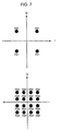
- Fig. 8 shows a block diagram of the base station and the communications apparatus.
- base station 602 determined the transmission environment to be GOOD by evaluating the transmission-environment-inference signal transmitted from the communications apparatus.
- a GOOD transmission environment as mentioned earlier, an amount of information to be transmitted can be increased to get the transmission speed higher, trading off slightly the receiving-electric-field intensity being kept at a sufficient level. In other words, it becomes possible to increase an assigned number of spreading signals per user in the spectrum-spreading system.
- a transmitter on the base station's side as shown in the lower part of the block diagram in Fig. 8, a plurality of modulating signals 819 and 826 are entered into spreaders 822 and 829, respectively.
- Fig. 8 shows the case of using two modulating signals.
- Entered modulating signals 819 and 826 are separately subjected to a spreading spectrum process using two different spreading signals 824 and 831 to generate spread signals 825 and 832, respectively. Then, these two signals are added by an adder circuit and fed out totally as spread signal 833, which is subjected to frequency-conversion at radio-frequency circuit 834 then transmitted via antenna 836. Meanwhile, in the communication apparatus, a signal received at antenna 837 is subjected to frequency-conversion at radio-frequency circuit 839. Frequency-converted signal 840 is branched into each de-spreader 841 and 845, where each signal is separately subjected to a de-spreading process to be generated de-spread signals 842 and 846,respectively.
- demodulators 843 and 847 demodulate these de-spread signals 842 and 846 to generate desired demodulated signals 844 and 848, respectively.
- a higher transmission speed can be obtained by increasing the assigned number of spreading signals and de-spreading signals at the transmitter's side and the receiver's side, respectively.
- the transmission speed is decreased by decreasing the assigned number of spreading signals in order to get a higher information quality.
- the number of modulating signals handled in the base station is decreased.
- Fig. 8 shows the case that the modulating signal is decreased to one.
- Modulator 802 outputs the modulated signal 803, further the signal is subjected to the spreading process with spreading signal 806 at spreader 804, resulting that spread spectrum signal 807 is generated. After frequency-conversion at radio-frequency circuit 808, the signal is transmitted from antenna 810.
- signal 814 which is received at antenna 811 then subjected to frequency-conversion at radio-frequency circuit 813, is further subjected to the de-spreading process at de-spreader 815.
- De-spread signal 816 which is generated in consequence of the de-spreading process, is demodulated in demodulator 817, resulting that desired demodulated signal 818 is obtained.
- the transmission environment is BAD
- the transmission speed is not expected to be better because the signals handled both at the transmitter's and receiver's sides are decreased in number. Instead, the information quality is greatly improved.
- the employed mobile-wireless-communications system of the embodiment allows base station 602 to change the transmitting power
- the information quality can be unproved by controlling the transmitting power with the following way.
- the transmitting power is maintained the current state, or decreased. Contrarily, when the transmission environment is BAD, the transmitting power can be increased to improve the receiving-electric-field intensity, so that the BER always can be kept at an appropriate level.
- the communications apparatus of the present invention calculates not only the Doppler frequency of the carrier waves based on its own velocity, but also the receiving-electric-field intensity based on the received radio wave, in order to represent these two calculated results as physical measures. According to the relation between these two physical measures and the data that is obtained from a transmission-environment model similar to the actual transmission environment, the condition of the current transmission environment of transmission paths is evaluated quantitatively. This allows the communications apparatus itself, or the base station, to optimize the BER and the transmitting speed, resulting in improved transmission quality.
Landscapes
- Engineering & Computer Science (AREA)
- Computer Networks & Wireless Communication (AREA)
- Signal Processing (AREA)
- Quality & Reliability (AREA)
- Physics & Mathematics (AREA)
- Electromagnetism (AREA)
- Mobile Radio Communication Systems (AREA)
Applications Claiming Priority (2)
| Application Number | Priority Date | Filing Date | Title |
|---|---|---|---|
| JP22968599 | 1999-08-16 | ||
| JP22968599 | 1999-08-16 |
Publications (1)
| Publication Number | Publication Date |
|---|---|
| EP1077533A1 true EP1077533A1 (fr) | 2001-02-21 |
Family
ID=16896102
Family Applications (1)
| Application Number | Title | Priority Date | Filing Date |
|---|---|---|---|
| EP00306746A Withdrawn EP1077533A1 (fr) | 1999-08-16 | 2000-08-08 | Terminal numérique mobile et sans fil, et système utilisant un tel terminal |
Country Status (2)
| Country | Link |
|---|---|
| US (1) | US6785545B1 (fr) |
| EP (1) | EP1077533A1 (fr) |
Cited By (3)
| Publication number | Priority date | Publication date | Assignee | Title |
|---|---|---|---|---|
| KR100405657B1 (ko) * | 2001-05-02 | 2003-11-14 | 엘지전자 주식회사 | 무선통신 시스템의 주파수 추정방법 및 장치 |
| GB2464289A (en) * | 2008-10-08 | 2010-04-14 | Samsung Electronics Co Ltd | Estimating link qualities in a multi-carrier wireless communication system |
| EP2346176A4 (fr) * | 2008-11-11 | 2015-05-13 | Nec Corp | Système de communication sans fil mobile, dispositif de communication mobile et procédé de réglage de fréquence |
Families Citing this family (2)
| Publication number | Priority date | Publication date | Assignee | Title |
|---|---|---|---|---|
| JP4770146B2 (ja) * | 2004-09-14 | 2011-09-14 | 日本電気株式会社 | 情報処理装置及び情報処理方法 |
| TWI305610B (en) * | 2006-07-07 | 2009-01-21 | Ind Tech Res Inst | Path guidance method for autonomous mobile device |
Citations (3)
| Publication number | Priority date | Publication date | Assignee | Title |
|---|---|---|---|---|
| GB2305825A (en) * | 1995-09-29 | 1997-04-16 | Nec Corp | Mobile telephone measuring channel condition at time intervals depending on velocity |
| US5781542A (en) * | 1994-12-02 | 1998-07-14 | Kabushiki Kaisha Toshiba | Information communication system using multi-code CDMA mode |
| EP0899906A2 (fr) * | 1997-08-25 | 1999-03-03 | Lucent Technologies Inc. | Système et méthode pour la mesure de qualité d'un canal |
Family Cites Families (10)
| Publication number | Priority date | Publication date | Assignee | Title |
|---|---|---|---|---|
| JP2748656B2 (ja) * | 1990-06-19 | 1998-05-13 | ソニー株式会社 | 移動無線通信方法 |
| JP2931771B2 (ja) | 1995-03-29 | 1999-08-09 | 日本無線株式会社 | 移動速度検出装置 |
| JPH08307924A (ja) | 1995-04-28 | 1996-11-22 | Kokusai Electric Co Ltd | 移動体通信の端末装置及びその制御方法 |
| JP2968706B2 (ja) | 1995-07-26 | 1999-11-02 | 日本電気エンジニアリング株式会社 | 移動無線機 |
| FI100072B (fi) * | 1996-01-19 | 1997-09-15 | Nokia Mobile Phones Ltd | Menetelmä lähetystehon säätämiseksi sekä radiojärjestelmä |
| US5771456A (en) | 1996-08-09 | 1998-06-23 | Trimble Navigation Limited | Enhanced suppression of multipath interference |
| JPH10145309A (ja) | 1996-11-05 | 1998-05-29 | Kokusai Electric Co Ltd | データ伝送システム |
| US5884178A (en) | 1996-11-27 | 1999-03-16 | Telefonaktiebolaget L M Ericsson (Publ) | Method and apparatus for estimating speed of a mobile station in a cellular communications system |
| EP1026906A4 (fr) * | 1998-06-30 | 2005-03-16 | Mitsubishi Electric Corp | Terminal de communication mobile |
| US6377813B1 (en) * | 1998-12-03 | 2002-04-23 | Nokia Corporation | Forward link closed loop power control for a third generation wideband CDMA system |
-
2000
- 2000-08-08 EP EP00306746A patent/EP1077533A1/fr not_active Withdrawn
- 2000-08-08 US US09/634,023 patent/US6785545B1/en not_active Expired - Fee Related
Patent Citations (3)
| Publication number | Priority date | Publication date | Assignee | Title |
|---|---|---|---|---|
| US5781542A (en) * | 1994-12-02 | 1998-07-14 | Kabushiki Kaisha Toshiba | Information communication system using multi-code CDMA mode |
| GB2305825A (en) * | 1995-09-29 | 1997-04-16 | Nec Corp | Mobile telephone measuring channel condition at time intervals depending on velocity |
| EP0899906A2 (fr) * | 1997-08-25 | 1999-03-03 | Lucent Technologies Inc. | Système et méthode pour la mesure de qualité d'un canal |
Cited By (4)
| Publication number | Priority date | Publication date | Assignee | Title |
|---|---|---|---|---|
| KR100405657B1 (ko) * | 2001-05-02 | 2003-11-14 | 엘지전자 주식회사 | 무선통신 시스템의 주파수 추정방법 및 장치 |
| GB2464289A (en) * | 2008-10-08 | 2010-04-14 | Samsung Electronics Co Ltd | Estimating link qualities in a multi-carrier wireless communication system |
| GB2464289B (en) * | 2008-10-08 | 2012-12-05 | Samsung Electronics Co Ltd | Estimating link qualities in multi-carrier systems |
| EP2346176A4 (fr) * | 2008-11-11 | 2015-05-13 | Nec Corp | Système de communication sans fil mobile, dispositif de communication mobile et procédé de réglage de fréquence |
Also Published As
| Publication number | Publication date |
|---|---|
| US6785545B1 (en) | 2004-08-31 |
Similar Documents
| Publication | Publication Date | Title |
|---|---|---|
| EP0928074B1 (fr) | Contrôle de la puissance de transmission dans un système de communication AMDC/TDD | |
| KR100318588B1 (ko) | 무선통신장치및무선통신방법 | |
| US7133698B2 (en) | Radio base station apparatus and radio communication method | |
| EP1655872A1 (fr) | Émetteur et récepteur de communication mobile pour une pluralité de schémas sans fil. | |
| EP1453211B1 (fr) | Système de radio-communications, station radio et procédé de radio-communication | |
| EP1200851B1 (fr) | Procede permettant de determiner un changement au niveau d'un signal de communication et d'utiliser ces informations pour ameliorer la reception et le traitement des signaux sps | |
| EP0987842A1 (fr) | Appareil pour station de base radio, et procede de radiocommunications | |
| US20040248519A1 (en) | Data transmission method, system and network element | |
| CN101517942B (zh) | 主动接收器检测和测距 | |
| JPH0974378A (ja) | 基地局送信電力制御方式 | |
| KR19990022258A (ko) | 저궤도 위성 통신 시스템을 위한 파일럿 신호 전력 제어 | |
| US20010043642A1 (en) | CDMA communication system and channel estimating method used in the same | |
| US6785545B1 (en) | Digital mobile wireless communications apparatus and the system using the same | |
| US6968212B1 (en) | Base station apparatus that directively transmits a modulated packet signal to a priority destination and packet transmission method thereto | |
| JP2010062997A (ja) | 無線通信装置 | |
| EP1328072B1 (fr) | Récepteur à spectre étalé pour la liason descendant à diversité d'antenne de transmission | |
| US20060014506A1 (en) | Dynamic carrier selection and link adaptation in fading environments | |
| EP1065802A1 (fr) | Procédé de commande de la puissance de transmission en mésurant l' Eb/No de la combinaison de signaux pondérés | |
| US8483607B2 (en) | Wireless communication method and relay apparatus | |
| CA2248516C (fr) | Appareil de reception | |
| EP1381173A2 (fr) | Appareil de communication sans fil | |
| JP2001127695A (ja) | 移動無線通信機およびこれを用いた移動無線通信システム | |
| KR101002923B1 (ko) | 휴대 통신 기기의 지향성 안테나 모듈을 위한 전파 환경계측 및 지향성 제어 장치 | |
| JP4877031B2 (ja) | 無線通信装置 | |
| EP1221777A1 (fr) | Méthode et appareil de classification d'interference |
Legal Events
| Date | Code | Title | Description |
|---|---|---|---|
| PUAI | Public reference made under article 153(3) epc to a published international application that has entered the european phase |
Free format text: ORIGINAL CODE: 0009012 |
|
| AK | Designated contracting states |
Kind code of ref document: A1 Designated state(s): DE FR GB |
|
| AX | Request for extension of the european patent |
Free format text: AL;LT;LV;MK;RO;SI |
|
| 17P | Request for examination filed |
Effective date: 20010509 |
|
| AKX | Designation fees paid |
Free format text: DE FR GB |
|
| 17Q | First examination report despatched |
Effective date: 20070119 |
|
| STAA | Information on the status of an ep patent application or granted ep patent |
Free format text: STATUS: THE APPLICATION IS DEEMED TO BE WITHDRAWN |
|
| 18D | Application deemed to be withdrawn |
Effective date: 20070530 |