EP1083368A2 - Ensemble rotatif d'une variateur de vitesse à friction et procédé de fabrication des éléments de roulement de tel ensemble - Google Patents
Ensemble rotatif d'une variateur de vitesse à friction et procédé de fabrication des éléments de roulement de tel ensemble Download PDFInfo
- Publication number
- EP1083368A2 EP1083368A2 EP00119126A EP00119126A EP1083368A2 EP 1083368 A2 EP1083368 A2 EP 1083368A2 EP 00119126 A EP00119126 A EP 00119126A EP 00119126 A EP00119126 A EP 00119126A EP 1083368 A2 EP1083368 A2 EP 1083368A2
- Authority
- EP
- European Patent Office
- Prior art keywords
- traction
- rotary assembly
- recesses
- rolling element
- contact surface
- Prior art date
- Legal status (The legal status is an assumption and is not a legal conclusion. Google has not performed a legal analysis and makes no representation as to the accuracy of the status listed.)
- Granted
Links
- 238000005096 rolling process Methods 0.000 title claims abstract description 434
- 238000000034 method Methods 0.000 title claims abstract description 25
- 230000008569 process Effects 0.000 title claims abstract description 25
- 238000000227 grinding Methods 0.000 claims description 45
- 230000003746 surface roughness Effects 0.000 claims description 40
- 229910000831 Steel Inorganic materials 0.000 claims description 38
- 239000010959 steel Substances 0.000 claims description 38
- 238000005496 tempering Methods 0.000 claims description 37
- 238000005520 cutting process Methods 0.000 claims description 33
- 238000003754 machining Methods 0.000 claims description 28
- 238000005480 shot peening Methods 0.000 claims description 20
- 239000000463 material Substances 0.000 claims description 19
- 230000014759 maintenance of location Effects 0.000 claims description 18
- 238000010438 heat treatment Methods 0.000 claims description 15
- 239000006061 abrasive grain Substances 0.000 claims description 13
- 238000005498 polishing Methods 0.000 claims description 13
- 230000005540 biological transmission Effects 0.000 claims description 10
- 238000005422 blasting Methods 0.000 claims description 3
- 238000005530 etching Methods 0.000 claims description 3
- 238000012360 testing method Methods 0.000 description 233
- 230000000052 comparative effect Effects 0.000 description 61
- 229910052751 metal Inorganic materials 0.000 description 23
- 239000002184 metal Substances 0.000 description 23
- 230000015572 biosynthetic process Effects 0.000 description 20
- 230000000694 effects Effects 0.000 description 20
- 238000010586 diagram Methods 0.000 description 13
- 238000004364 calculation method Methods 0.000 description 10
- 238000004519 manufacturing process Methods 0.000 description 9
- 239000012530 fluid Substances 0.000 description 7
- 230000007246 mechanism Effects 0.000 description 7
- 239000002245 particle Substances 0.000 description 5
- 238000010008 shearing Methods 0.000 description 5
- 230000008859 change Effects 0.000 description 3
- 230000006872 improvement Effects 0.000 description 3
- 229910052582 BN Inorganic materials 0.000 description 2
- PZNSFCLAULLKQX-UHFFFAOYSA-N Boron nitride Chemical compound N#B PZNSFCLAULLKQX-UHFFFAOYSA-N 0.000 description 2
- 238000009826 distribution Methods 0.000 description 2
- 239000003792 electrolyte Substances 0.000 description 2
- 238000011056 performance test Methods 0.000 description 2
- 238000011160 research Methods 0.000 description 2
- VZSRBBMJRBPUNF-UHFFFAOYSA-N 2-(2,3-dihydro-1H-inden-2-ylamino)-N-[3-oxo-3-(2,4,6,7-tetrahydrotriazolo[4,5-c]pyridin-5-yl)propyl]pyrimidine-5-carboxamide Chemical compound C1C(CC2=CC=CC=C12)NC1=NC=C(C=N1)C(=O)NCCC(N1CC2=C(CC1)NN=N2)=O VZSRBBMJRBPUNF-UHFFFAOYSA-N 0.000 description 1
- ISWSIDIOOBJBQZ-UHFFFAOYSA-N Phenol Chemical compound OC1=CC=CC=C1 ISWSIDIOOBJBQZ-UHFFFAOYSA-N 0.000 description 1
- ATJFFYVFTNAWJD-UHFFFAOYSA-N Tin Chemical compound [Sn] ATJFFYVFTNAWJD-UHFFFAOYSA-N 0.000 description 1
- 239000011230 binding agent Substances 0.000 description 1
- VNTLIPZTSJSULJ-UHFFFAOYSA-N chromium molybdenum Chemical compound [Cr].[Mo] VNTLIPZTSJSULJ-UHFFFAOYSA-N 0.000 description 1
- 239000011248 coating agent Substances 0.000 description 1
- 238000000576 coating method Methods 0.000 description 1
- 230000006835 compression Effects 0.000 description 1
- 238000007906 compression Methods 0.000 description 1
- 238000010276 construction Methods 0.000 description 1
- 230000008878 coupling Effects 0.000 description 1
- 238000010168 coupling process Methods 0.000 description 1
- 238000005859 coupling reaction Methods 0.000 description 1
- 229910003460 diamond Inorganic materials 0.000 description 1
- 239000010432 diamond Substances 0.000 description 1
- 239000003822 epoxy resin Substances 0.000 description 1
- 239000000446 fuel Substances 0.000 description 1
- 238000010191 image analysis Methods 0.000 description 1
- 238000005461 lubrication Methods 0.000 description 1
- FXNGWBDIVIGISM-UHFFFAOYSA-N methylidynechromium Chemical group [Cr]#[C] FXNGWBDIVIGISM-UHFFFAOYSA-N 0.000 description 1
- 238000012986 modification Methods 0.000 description 1
- 230000004048 modification Effects 0.000 description 1
- TWNQGVIAIRXVLR-UHFFFAOYSA-N oxo(oxoalumanyloxy)alumane Chemical compound O=[Al]O[Al]=O TWNQGVIAIRXVLR-UHFFFAOYSA-N 0.000 description 1
- 229920000647 polyepoxide Polymers 0.000 description 1
- 238000003825 pressing Methods 0.000 description 1
- 239000000700 radioactive tracer Substances 0.000 description 1
- 229920005989 resin Polymers 0.000 description 1
- 239000011347 resin Substances 0.000 description 1
- 230000035939 shock Effects 0.000 description 1
- 238000009751 slip forming Methods 0.000 description 1
- 229910001220 stainless steel Inorganic materials 0.000 description 1
- 238000005482 strain hardening Methods 0.000 description 1
- 230000002459 sustained effect Effects 0.000 description 1
Images







Classifications
-
- F—MECHANICAL ENGINEERING; LIGHTING; HEATING; WEAPONS; BLASTING
- F16—ENGINEERING ELEMENTS AND UNITS; GENERAL MEASURES FOR PRODUCING AND MAINTAINING EFFECTIVE FUNCTIONING OF MACHINES OR INSTALLATIONS; THERMAL INSULATION IN GENERAL
- F16H—GEARING
- F16H55/00—Elements with teeth or friction surfaces for conveying motion; Worms, pulleys or sheaves for gearing mechanisms
- F16H55/32—Friction members
-
- F—MECHANICAL ENGINEERING; LIGHTING; HEATING; WEAPONS; BLASTING
- F16—ENGINEERING ELEMENTS AND UNITS; GENERAL MEASURES FOR PRODUCING AND MAINTAINING EFFECTIVE FUNCTIONING OF MACHINES OR INSTALLATIONS; THERMAL INSULATION IN GENERAL
- F16H—GEARING
- F16H15/00—Gearings for conveying rotary motion with variable gear ratio, or for reversing rotary motion, by friction between rotary members
- F16H15/02—Gearings for conveying rotary motion with variable gear ratio, or for reversing rotary motion, by friction between rotary members without members having orbital motion
- F16H15/04—Gearings providing a continuous range of gear ratios
- F16H15/06—Gearings providing a continuous range of gear ratios in which a member A of uniform effective diameter mounted on a shaft may co-operate with different parts of a member B
- F16H15/32—Gearings providing a continuous range of gear ratios in which a member A of uniform effective diameter mounted on a shaft may co-operate with different parts of a member B in which the member B has a curved friction surface formed as a surface of a body of revolution generated by a curve which is neither a circular arc centered on its axis of revolution nor a straight line
- F16H15/36—Gearings providing a continuous range of gear ratios in which a member A of uniform effective diameter mounted on a shaft may co-operate with different parts of a member B in which the member B has a curved friction surface formed as a surface of a body of revolution generated by a curve which is neither a circular arc centered on its axis of revolution nor a straight line with concave friction surface, e.g. a hollow toroid surface
- F16H15/38—Gearings providing a continuous range of gear ratios in which a member A of uniform effective diameter mounted on a shaft may co-operate with different parts of a member B in which the member B has a curved friction surface formed as a surface of a body of revolution generated by a curve which is neither a circular arc centered on its axis of revolution nor a straight line with concave friction surface, e.g. a hollow toroid surface with two members B having hollow toroid surfaces opposite to each other, the member or members A being adjustably mounted between the surfaces
-
- F—MECHANICAL ENGINEERING; LIGHTING; HEATING; WEAPONS; BLASTING
- F16—ENGINEERING ELEMENTS AND UNITS; GENERAL MEASURES FOR PRODUCING AND MAINTAINING EFFECTIVE FUNCTIONING OF MACHINES OR INSTALLATIONS; THERMAL INSULATION IN GENERAL
- F16H—GEARING
- F16H55/00—Elements with teeth or friction surfaces for conveying motion; Worms, pulleys or sheaves for gearing mechanisms
- F16H55/32—Friction members
- F16H2055/325—Friction members characterized by roughness or hardness of friction surface
-
- Y—GENERAL TAGGING OF NEW TECHNOLOGICAL DEVELOPMENTS; GENERAL TAGGING OF CROSS-SECTIONAL TECHNOLOGIES SPANNING OVER SEVERAL SECTIONS OF THE IPC; TECHNICAL SUBJECTS COVERED BY FORMER USPC CROSS-REFERENCE ART COLLECTIONS [XRACs] AND DIGESTS
- Y10—TECHNICAL SUBJECTS COVERED BY FORMER USPC
- Y10T—TECHNICAL SUBJECTS COVERED BY FORMER US CLASSIFICATION
- Y10T82/00—Turning
- Y10T82/18—Lathe for wheel or axle
-
- Y—GENERAL TAGGING OF NEW TECHNOLOGICAL DEVELOPMENTS; GENERAL TAGGING OF CROSS-SECTIONAL TECHNOLOGIES SPANNING OVER SEVERAL SECTIONS OF THE IPC; TECHNICAL SUBJECTS COVERED BY FORMER USPC CROSS-REFERENCE ART COLLECTIONS [XRACs] AND DIGESTS
- Y10—TECHNICAL SUBJECTS COVERED BY FORMER USPC
- Y10T—TECHNICAL SUBJECTS COVERED BY FORMER US CLASSIFICATION
- Y10T82/00—Turning
- Y10T82/25—Lathe
- Y10T82/2522—Portable
Definitions
- the present invention relates to a continuously variable transmission (CVT) for traction drives which is used to transmit rotation from an input side to an output side while continuously varying the speed by traction drive in a power transmission device of an automobile, industrial machinery and so forth, and more particularly, to a rotary assembly for traction drives which includes a rolling element having a traction contact surface which exhibits excellent traction characteristics as surface properties.
- CVT continuously variable transmission
- Rotary assembly 1 for traction drive type CVTs.
- Rotary assembly 1 includes two metal rolling elements, namely, two disks (input disk 3 circumferentially fixed on input shaft 2 and output disk 5 circumferentially fixed on output shaft 4), and power roller 6 interposed between the rolling elements and contacted therewith through a traction oil.
- Power roller 6 has a tiltable roller shaft such that power roller 6 is inclined relative to input and output disks 3 and 5 when the roller shaft tilts. Owing to the inclination of power roller 6, the contact between power roller 6 and input and output disks 3 and 5 shifts. This changes the ratio of the torque radius of input disk 3 to that of output disk 5 to thereby continuously change the transmission ratio.
- a half toroidal type CVT is one of traction drive CVTs.
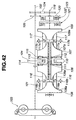
- Fig. 42 illustrates a toroidal type CVT which includes input shaft 101 and output shaft 102 coaxial with input shaft 101 and rotatable relative thereto.
- An engine torque is supplied via fluid coupling 103 to input shaft 101.
- Forward and reverse input gears 104 and 105 are disposed on input shaft 101 so as to make a unitary rotation therewith.
- Two input disks 106 and 107 are drivingly connected with each other through hollow shaft 112 extending parallel to input shaft 101.
- Two output disks 108 and 109 are arranged in an opposed relation to input disks 106 and 107 and connected with each other via shaft 111 extending inside hollow shaft 112.
- Drive plate 110 is disposed between input disks 106 and 107 and drivingly connected therewith by loading cams 114 and 115.
- Gear 113 integrally formed with drive plate 110 is engageable with forward input gear 104.
- Two power rollers 116 are disposed between opposed input and output disks 106 and 108 and in friction contact with traction contact surfaces 106a and 108a thereof.
- Two power rollers 117 are disposed between opposed input and output disks 107 and 109 and in friction contact with traction contact surfaces 107a and 109a thereof.
- Power rollers 116 and 117 are rotatable about axes 116a and 117a thereof to transmit the torque from input disks 106 and 107 to output disks 108 and 109, respectively.
- Power rollers 116 and 117 are also adapted to offset or swing in directions of axes 116b and 117b extending perpendicular to axes 116a and 117a, respectively.
- Forward/reverse change mechanism 123 is disposed on final drive shaft 119 disposed coaxially with input shaft 101.
- Gear 120 rotatably supported on final drive shaft 119 is engageable with reverse input gear 105.
- Forward/reverse change mechanism 123 includes forward clutch 121 connecting final drive shaft 119 with output disk 109 and reverse clutch 122 connecting final drive shaft 119 with gear 120.
- Final drive shaft 119 is also connected with output shaft 102 via chain transmission mechanism 124.
- Such a toroidal type CVT is disclosed in Japanese Patent Application First Publication No. 62-251559.
- the rolling elements namely, input disk 3, output disk 5, power roller 6, of rotary assembly 1 shown in Fig. 1, are required to have excellent traction characteristics and high rolling fatigue life characteristics under high temperature and high bearing pressure.
- vehicle weight in consideration of the future burden on the environment, it is necessary that vehicle weight be reduced to achieve further improvement of fuel economy.
- the unit size must be reduced, and in the case of units of the same size, it is necessary to increase the motive power that can be transmitted.
- the object of the present invention is to provide a traction drive rotary assembly capable of transmitting large motive power and having excellent traction characteristics.
- a rotary assembly for traction drives comprising:
- a rotary assembly for traction drives comprising a plurality of rolling elements having a rotation axis and traction contact surfaces around the rotation axis and associating with each other to transmit a motive power between the rolling elements via a traction oil film formed between the traction contact surfaces, at least one of said traction contact surfaces having a microstructure with irregularities which sizes are larger than a thickness of the traction oil film, wherein the traction contact surface is formed by a process, the process comprising:
- a rotary assembly for traction drives comprising a plurality of rolling elements having a rotation axis and traction contact surfaces around the rotation axis and associating with each other to transmit a motive power between the rolling elements via a traction oil film formed between the traction contact surfaces, at least one of said traction contact surfaces having a microstructure with irregularities which sizes are larger than a thickness of the traction oil film, the microstructure being represented by an unfiltered primary profile curve including alternately arranged recesses and top-flat lands, wherein the traction contact surface is produced by a process, the process comprising:
- a rotary assembly for traction drives comprising a plurality of rolling elements having a rotation axis and traction contact surfaces around the rotation axis and associating with each other to transmit a motive power between the rolling elements via a traction oil film formed between the traction contact surfaces, at least one of said traction contact surfaces having a microstructure with irregularities which sizes are larger than a thickness of the traction oil film, the microstructure being represented by an unfiltered primary profile curve including alternately arranged recesses and top-flat lands, wherein the traction contact surface is produced by a process, the process comprising:
- the traction drive rotary assembly of the present invention includes rolling elements having a rotation axis and traction contact surfaces around the rotation axis which associate with each other to transmit a motive power between the rolling elements via a traction oil film formed between the traction contact surfaces, wherein at least one of the traction contact surfaces has a microstructure with irregularities which sizes are larger than a thickness of the traction oil film.
- the sizes of the irregularities can be effectively associated with the thickness of a traction oil film in EHL (Elasto-Hydrodynamic Lubrication) that is formed upon rotation of the drive-side and driven-side rolling elements.
- EHL Easy-Hydrodynamic Lubrication
- the irregularities of the microstructure of the traction contact surface are in the form of alternately arranged dimples and top-flat lands and the dimples include dimples having a diameter of 5-30 ⁇ m and a depth of 0.1-1.0 ⁇ m that extends substantially perpendicular to the diameter, and occupying 5-40% of a reference area of the traction contact surface.
- the surface area ratio of the dimples having the diameter of 5-30 ⁇ m and the depth of 0.1-1.0 ⁇ m is less than 5%, traction characteristics do not greatly improve, while if the surface area ratio exceeds 40%, it is likely that the metal contact will occur which will cause undesirable effect on durability.
- the microstructure of the traction contact surface can exhibit more stable excellent traction characteristics by forming approximately 10-30 dimples per 100 ⁇ m 2 which have a diameter of 5-30 ⁇ m and a depth of 0.1-1.0 ⁇ m extending substantially perpendicular to the diameter. If the number of the dimples is less than 10 per 100 ⁇ m 2 , traction characteristics do not greatly improve, while if the number of the dimples is greater than 30 per 100 ⁇ m 2 , it is likely that the metal contact will occur which will cause undesirable effect on durability.
- arithmetical mean roughness Ra
- Ry maximum height
- traction characteristics are not greatly improved.
- the arithmetical mean roughness is greater than 0.15 ⁇ m or the maximum height is greater than 1.0 ⁇ m, it is likely that the metal contact will occur which will cause undesirable effect on durability.
- the rolling element which has satisfactory wear resistance and excellent traction characteristics, can be easily produced by forming the traction contact surface having the microstructure with alternately arranged dimples and top-flat lands which is produced by subjecting a surface of the rolling element to shot-peening to form recesses and projections therein and then machining the projections by either one of lapping, mirror polishing, super finishing, cutting or grinding to form the top-flat lands and thus produce the traction contact surface.
- the irregularities of the microstructure of the traction contact surface are in the form of alternately arranged circumferentially extending grooves and top-flat lands, in which the grooves have a width of 2-10 ⁇ m extending along the rotation axis of the rolling element, a pitch or interval of 10-30 ⁇ m between the adjacent two grooves, and a depth of 0.1-1.0 ⁇ m extending from a bottom thereof in a direction substantially perpendicular to the rotation axis of the rolling element.
- the surface roughness of the traction contact surface is made such that an arithmetical mean roughness (Ra) is 0.03-0.13 ⁇ m or a maximum height (Ry) is 0.2-0.9 ⁇ m.
- arithmetical mean roughness is less than 0.03 ⁇ m or the maximum height is less than 0.2 ⁇ m, the improvement in traction characteristics is not considerable.
- the arithmetical mean roughness exceeds 0.13 ⁇ m or the maximum height exceeds 0.9 ⁇ m, it is likely that the metal contact will occur which will cause undesirable effect on durability.
- the traction drive rotary assembly of the present invention can exhibit better traction characteristics by making a ratio (Sm/a) of a mean space (Sm) between the irregularities of the microstructure of the traction contact surface to a half (a) of a major axis diameter of a Hertzian contact ellipse 0.08 or less.
- the microstructure of the traction contact surface of the rolling element is represented by an unfiltered primary profile curve including alternately arranged recesses and top-flat lands.
- the unfiltered primary profile curve is measured using a surface roughness tester (without passing through a filter).
- a portion of each land higher than a center line with respect to the unfiltered primary profile curve namely, a line drawn at a mean height determined by integrally converting the unfiltered primary profile curve in the direction of length, has either one shape selected from a generally trapezoidal shape, a generally trapezoidal shape with rounded corners, a generally trapezoidal shape with chamfered corners, a generally crowning shape, a part of a generally elliptic arc shape, a generally sinusoidal shape and a generally triangular shape with a rounded apex. This can generate large traction force while holding metal contact to a low level, and transmit large motive power.
- the traction contact surface has the microstructure in which a height difference between a top of each land and a bottom of each recess is 0.5-2.5 ⁇ m. This can transmit large motive power and exhibit excellent traction characteristics. If the height difference is less than 0.5 ⁇ m, traction characteristics are not greatly improved, and if the height difference is greater than 2.5 ⁇ m, it is likely that the metal contact will occur which will cause undesirable effect on durability.
- the traction contact surface has the microstructure in which a height difference between a top of each land and a bottom of each recess is 2.0-2.5 ⁇ m. This can exhibit more stable and better traction characteristics.
- the traction drive rotary assembly of the present invention can further lower concern over the occurrence of metal contact causing undesirable effect on durability and have better traction characteristics, with an arrangement in which the height difference between the top of each land and the bottom of each recess is 0.8-1.2 ⁇ m.
- the traction contact surface has the microstructure in which with respect to the center line separated into segments by crossing with the unfiltered primary profile curve, a ratio of a total length of the segments corresponding to the recesses to a reference length of the center line is within a range of 15-60%. Namely, a ratio of a length of the segment corresponding to the land to a length of the segment corresponding to the recess is within a range of 5.7-0.6. This can demonstrate a large traction coefficient with greater stability. If the ratio is less than 15%, traction characteristics are not greatly improved, and if the ratio is greater than 60%, it is likely that the metal contact will occur which will cause undesirable effect on durability.
- the traction contact surface has the microstructure in which with respect to the center line separated into segments by crossing with the unfiltered primary profile curve, a ratio of a total length of the segments corresponding to the recesses to a reference length of the center line is within a range of 25-40%. Namely, a ratio of a length of the segment corresponding to the land to a length of the segment corresponding to the recess is within a range of 3.0-1.5. This can exhibit better traction characteristics with greater stability.
- the traction contact surface has the microstructure in which the ratio of a total length of the segments corresponding to the recesses to the reference length of the center line is within a range of 27-35%. Namely, the ratio of a length of the segment corresponding to the land to a length of the segment corresponding to the recess is within a range of 2.7-1.8. This can further lower concern over the occurrence of metal contact causing undesirable effect on durability and have better traction characteristics.
- the traction contact surface has the microstructure in which the ratio of a total length of the segments corresponding to the recesses to the reference length of the center line is within a range of 30-57%. Namely, the ratio of a length of the segment corresponding to the land to a length of the segment corresponding to the recess is within a range of 2.3-0.8. This can exhibit better traction characteristics with much greater stability.
- the traction contact surface has the microstructure in which with respect to the center line separated into segments by crossing with the unfiltered primary profile curve, a pitch of the recesses is within a range of 10-150 ⁇ m. This can exhibit excellent traction characteristics with greater stability. If the pitch is greater than 150 ⁇ m, traction characteristics are not greatly improved, and if the pitch is less than 10 ⁇ m, it is likely that the metal contact will occur which will cause undesirable effect on durability.
- the traction contact surface has the microstructure in which the pitch of the recesses is within a range of 40-120 ⁇ m. This can exhibit better traction characteristics with much greater stability.
- the traction contact surface has the microstructure in which the surface roughness (as measured with an interatomic microscope) of a top portion of each land is made such that a ten-point mean roughness (Rz) is 100 nm or less. This can demonstrate a large traction coefficient. If the surface roughness is such that Rz is greater than 100 nm, it is likely that the metal contact will occur which will cause undesirable effect on durability.
- the traction contact surface has the microstructure in which the surface roughness of the top portion of the land is made such that Rz is 40 nm or less. This can further lower concern over the occurrence of metal contact causing undesirable effect on durability and exhibit better traction characteristics.
- the traction contact surface has the microstructure in which a length (width) of each segment corresponding to each recess is within a range of 10-40 ⁇ m. This can demonstrate a large traction coefficient. If the length of the recess is less than 10 ⁇ m, the improvement in traction characteristics is not remarkable, and if the length of the recess is greater than 40 ⁇ m, it is likely that the metal contact will occur which will cause undesirable effect on durability.
- the traction contact surface has the microstructure in which a ratio of a pitch of the recesses to a major axis diameter of a Hertzian contact ellipse made at a maximum load, which extends perpendicular to a rotating direction of the rolling element, is within a range of 1.2-9%. This can demonstrate a large traction coefficient with stability and lower concern over the occurrence of metal contact causing undesirable effect on durability.
- the ratio of the pitch of the recesses to the major axis diameter of the Hertzian contact ellipse made at the maximum load is preferably within a range of 2.4-6%. This can exhibit better traction characteristics with greater stability.
- the traction contact surface has the microstructure in which, with respect to the center line separated into segments by crossing with the unfiltered primary profile curve, a ratio of a length of each segment corresponding to each recess to the major axis diameter of the Hertzian contact ellipse made at the maximum load, which extends perpendicular to the rotating direction of the rolling element, is within a range of 0.6-2%. This can demonstrate a large traction coefficient with stability and lower concern over the occurrence of metal contact causing undesirable effect on durability.
- the traction contact surface has the microstructure in which the ratio of a length of each segment corresponding to each recess to the minor axis diameter of the Hertzian contact ellipse made at the maximum load, which extends parallel to the rotating direction of the rolling element, is within a range of 0.8-3.2%. This can demonstrate a large traction coefficient with stability and lower concern over the occurrence of metal contact causing undesirable effect on durability.
- the traction contact surface has the microstructure in which the recesses are grooves which are disposed substantially parallel to the rolling direction of the rolling element. This can demonstrate a large traction coefficient. If the direction of the recesses is not substantially parallel to the rolling direction of the rolling element, traction characteristics are not greatly improved.
- the traction contact surface has the microstructure in which the recesses are grooves which spirally extend along the rolling direction of the rolling element. This can demonstrate a large traction coefficient and can produce efficiently in a short time by the formation of the continuous recesses.
- the traction contact surface has the microstructure in which the recesses extend longer than at least a minor axis diameter of the Hertzian contact ellipse. This can demonstrate a large traction coefficient. If the recesses extend shorter than the minor axis diameter of the Hertzian contact ellipse, traction characteristics are not greatly improved.
- the traction contact surface has the microstructure in which a radius of curvature of a top portion of each top-flat land of the unfiltered primary profile curve measured using the surface roughness tester which is set at equal longitudinal and lateral magnifications, is 0.1-170 mm. This can demonstrate a larger traction coefficient. If the radius of curvature of the top portion of the projection is less than 0.1 mm, it is likely that the metal contact will occur which will cause undesirable effect on durability.
- the traction contact surface has the microstructure in which a radius of curvature of a top portion of each top-flat land of the unfiltered primary profile curve measured using the surface roughness tester which is set at equal longitudinal and lateral magnifications, is 0.8-170 mm. This can further lower concern over the occurrence of metal contact causing undesirable effect on durability and can demonstrate a larger traction coefficient. If the radius of curvature of the top portion of the land is greater than 170 mm, traction characteristics are not greatly improved.
- the traction contact surface has the microstructure in which a radius of curvature of a top portion of the top-flat land of the unfiltered primary profile curve measured using the surface roughness tester which is set at equal longitudinal and lateral magnifications, is 0.8-10 mm. This can further lower concern over the occurrence of metal contact causing undesirable effect on durability and can demonstrate a larger traction coefficient. If the radius of curvature of the top portion of the land is limited to 10 mm or less, better traction characteristics can be obtained.
- the traction contact surface of one of the drive-side and driven-side rolling elements has the microstructure with irregularities, and the traction contact surface of the other of the drive-side and driven-side rolling elements has an arithmetical mean roughness Ra of 0.05 ⁇ m or less. This can demonstrate a large traction coefficient with greater stability and cause little concern over the occurrence of metal contact causing undesirable effect on durability.
- the material of the rolling element and heat treatment therefor is selected from carburizing-quenching-tempering of case hardening steel, carbonitriding-quenching-tempering of case hardening steel, quenching-tempering of bearing steel, carburizing-quenching-tempering of bearing steel and carbonitriding-quenching-tempering of bearing steel.
- This can exhibit satisfactory wear resistance and excellent traction characteristics and transmit large motive power over a long period of time.
- the traction drive rotary assembly of the present invention can be used as an element of a half-toroidal continuously variable transmission that is capable of transmitting large motive power, reducing unit size and weight, and increasing power output per unit volume and unit weight.
- the traction drive rotary assembly of the invention includes rotatably and coaxially arranged input and output disks, having opposed traction contact surfaces in the shape of an annular concaved surface, and power rollers that are juxtaposed between the traction contact surfaces of the input and output disks, formed with annular convexed traction contact surfaces rotatable relative to the traction contact surfaces of the input and output disks, and have rotation axes inclinable relative to a rotation axis of the disks.
- the at least one of the traction contact surfaces of the rolling elements can be readily produced with high accuracy by forming recesses having a depth of 10 ⁇ m or less in a surface of the rolling element at equal intervals to form alternate arrangement of the recesses and projections, and, subsequent to the forming, machining the projections such that a height difference between a top of each top-flat land of the unfiltered primary profile curve and a bottom of each recess thereof is within a range of 0.5-2.5 ⁇ m.
- a shape of the top-flat lands of the unfiltered primary profile curve, a height difference between the recesses and the lands of the unfiltered primary profile curve, a ratio of a total length of the segments of the center line which correspond to the recesses of the unfiltered primary profile curve, to a reference length of the center line, a pitch of the recesses and a surface roughness of the lands and the like, are formed to the predetermined shapes and values.
- the at least one of the traction contact surfaces of the rolling elements can be readily produced with high accuracy by making a surface roughness of a surface of the rolling element a ten-point mean roughness Rz of 100 nm or less, and then by forming recesses each having a depth of 0.5-2.5 ⁇ m at equal intervals in the surface of the rolling element to form alternate arrangement of the recesses and top-flat lands between the recesses.
- a surface roughness of a surface of the rolling element a ten-point mean roughness Rz of 100 nm or less
- recesses each having a depth of 0.5-2.5 ⁇ m at equal intervals in the surface of the rolling element to form alternate arrangement of the recesses and top-flat lands between the recesses.
- a shape of the lands of the unfiltered primary profile curve, a height difference between the recesses and lands of the unfiltered primary profile curve, a ratio of a total length of the segments of the center line, which correspond to the recesses of the unfiltered primary profile curve, to a reference length of the center line, a pitch of the recesses and the like, are formed to the predetermined shapes and values.
- the at least one of the traction contact surfaces of the rolling elements can be produced with high accuracy by forming recesses by at least one machining selected from cutting, grinding, blasting, laser machining and etching and by forming top-flat lands by at least one machining selected from super finishing, lapping, cutting, grinding and electrolytic polishing.
- a shape of the top-flat lands of the unfiltered primary profile curve, a height difference between the recesses and the lands of the unfiltered primary profile curve, a ratio of a total length of the segments of the center line, which correspond to the recesses of the unfiltered primary profile curve, to a reference length of the center line, a pitch of the recesses and a surface roughness of the lands and the like, are formed to the predetermined shapes and values.
- the high-accurately formed microstructure can be provided corresponding to variety of the irregularities by selecting the machining for the recesses and the lands, respectively.
- the at least one of the traction contact surfaces of the rolling elements can be produced with high accuracy and in a short period of time, by forming recesses and projections by at least one machining selected from shot peening, grinding, cutting and super finishing and by forming the projections into top-flat lands having smoothened surfaces by roller burnishing.
- a shape of the top-flat lands of the unfiltered primary profile curve, a height difference between the recesses and the lands of the unfiltered primary profile curve, a ratio of a total length of the segments of the center line, which correspond to the recesses of the unfiltered primary profile curve, to a reference length of the center line, a pitch of the recesses and a surface roughness of the lands and the like, are formed to the predetermined shapes and values.
- the process by roller burnishing serves for reducing the time required for forming the lands as compared with the process by lapping and mirror polishing, so that the production cost can be lowered.
- the traction contact surface can be improved as a result of compression residual stress generated in the surface of the rolling element during the working and work hardening caused by the stress.
- the top-flat lands can be provided with the edges more rounded than the edges of the lands formed by, for instance, lapping. This can considerably reduce occurrence of damage caused by the edges of the lands onto the traction contact surface, further improving the durability.
- the at least one of the traction contact surfaces of the rolling elements can be produced in which the recesses of a predetermined dimension are formed with high accuracy using a tool having a blade tip end that has at least one shape selected from a single R (radius), a trapezoidal shape, a V-shape and a complex R and a width of 4-150 ⁇ m at a location spaced from the blade tip end by 0.5-2.5 ⁇ m.
- the at least one of the traction contact surfaces of the rolling elements can be produced in which the recesses of a predetermined dimension are formed with high accuracy by turning using a tool having a round blade tip end having an R of 0.2 mm or less.
- the at least one of the traction contact surfaces of the rolling elements can be formed in a short time by simultaneously forming recesses and top-flat lands using a single tool that has cutting blades corresponding to the recesses and the lands, respectively, and has a dimensional difference therebetween is 0.5-2.5 ⁇ m.
- a height difference between the recesses and the top-flat lands of the unfiltered primary profile curve of the traction contact surface is within a range of 0.5-2.5 ⁇ m.
- the at least one of the traction contact surfaces of the rolling elements in which the ten-point mean roughness Rz of top portions of top-flat lands of the unfiltered primary profile curve is 100 nm or less or 40 nm or less can be formed by machining the lands using a fixed abrasive grain tool having abrasive grains of a mean grain diameter of 9 ⁇ m or less.
- the at least one of the traction contact surfaces of the rolling elements in which the ten-point mean roughness Rz of top portions of the top-flat lands of the unfiltered primary profile curve is 100 nm or less or 40 nm or less, can be produced by forming the lands using an elastic grindstone having abrasive grains of a mean grain diameter of 30 ⁇ m or less.
- the at least one of the traction contact surfaces of the rolling elements can be produced in the following manner.
- the rolling element is rotated about a center axis and at the same time the rolling element and a tool are relatively moved in at least one direction selected from a direction of the center axis of the rolling element and a direction perpendicular to the center axis while being in contact with each other.
- the microstructure of the traction contact surface can be formed in which the recesses are formed continuously and in a short period of time along the rotating direction of the rolling element, and in the case of performing grinding after forming the recesses, abrasive grains or cuttings can be smoothly discharged because the recesses are spirally shaped, so that grinding can be performed with a good cutting edge at all times and finishing machining can be performed efficiently.
- Two rolling elements (test pieces) 22 and 24 of the traction drive rotary assembly of the invention were produced in the following manner.
- One (flat test piece) 24 of the rolling elements was made of JIS SCM420H steel (chromium molybdenum steel) subjected to carburizing-quenching-tempering and formed to a cylindrical shape having a diameter of 40 mm and a thickness of 20 mm and a flat cylindrical outer surface which was to be formed as the traction contact surface.
- the outer surface of rolling element (flat test piece) 24 was shot-peened by a pneumatic shot-peening machine at an air pressure of 0.5 MPa and using steel balls having a Vickers hardness of Hv750 and a mean particle diameter of 0.05 mm.
- the projector nozzle was oscillated in a direction of the axis of rotation of rolling element (flat test piece) 24 while rotating rolling element (flat test piece) 24 so that an amount of ball-projection was substantially uniform over the entire outer surface.
- the ball-projection time was set at 20 sec. Random recesses and projections were formed in the outer surface of rolling element (flat test piece) 24 by the shot peening. After the shot-peening treatment, the projections in the outer surface were cut away by tape lapping. The traction contact surface of rolling element (flat test piece) 24 was thus formed, which had a microstructure in the form of a combination of dimples and top-flat lands.
- dimples having a diameter of 5-30 ⁇ m and a depth of 0.1-1.0 ⁇ m occupied 38% of a reference area of the traction contact surface, and the number of the dimples was 28 per 100 ⁇ m 2 .
- the arithmetical mean roughness Ra described in JIS B0601-1994 of the traction contact surface was 0.121 ⁇ m and the maximum height Ry described in JIS B0601-1994 was 0.780 ⁇ m.
- the other rolling element (crowning test piece) 22 was made of JIS SCM420H steel subjected to carburizing-quenching-tempering and formed to a cylindrical shape having a diameter of 40 mm and a thickness of 20 mm and a crowning-shaped outer surface having an R (radius) 700 mm which was to be formed as the traction contact surface.
- the outer surface of rolling element (crowning test piece) 22 was subjected to grinding and super finishing.
- the traction contact surface of rolling element (crowning test piece) 22 was thus formed, in which the arithmetical mean roughness Ra was 0.021 ⁇ m and the maximum height Ry was 0.155 ⁇ m.
- two-cylinder rolling tester 21 includes driven shaft 25 that supports rolling element (crowning test piece) 22, and main shaft 23 that supports rolling element (flat test piece) 24.
- Torque sensor 26 is provided on main shaft 23.
- Main shaft timing belt 28 is spanned on main shaft 23 and motor shaft 27a of servo motor 27.
- Driven shaft 25 is fixed on sliding base 34 that is movable in a direction perpendicular to the axial direction through bearing 29.
- Driven shaft timing belt 31 is spanned on driven shaft 25 and motor shaft 30a of servo motor 30 that is also fixed on sliding base 34 with servo motor 30.
- Both of rolling elements (test pieces) 22 and 24 make rolling contact by applying pressure to sliding base 34 with air cylinder 32.
- Traction coefficient can be calculated by measuring the torque generated at main shaft 23 by torque sensor 26 provided in the motive power transmission system (main shaft 23) on the side of rolling element (flat test piece) 24.
- the slide/roll ratio was 0-5%
- the mean rotation velocity was 5.2 m/s
- the mean shaft rotation number was 500 rpm (the sum of the rotation numbers of main shaft 23 and driven shaft 25 was 1000 rpm)
- the rotation velocity was assumed to be constant by uniformly applying a differential to main shaft 23 and driven shaft 25.
- the rolling contact between one rolling element (crowning test piece) 22 and the other rolling element (flat test piece) 24 was conducted in oil bath 33 containing a traction oil set at 100°C.
- Nissan CVT fluid KTF-1 Example 1
- the vertical load generated by the pressure applied by air cylinder 32 was set at 147 N.
- Both rolling elements (test pieces) 24 and 22 were produced in the same manner as described in Example 1, except for different conditions as listed in Tables 1 and 2. Thus-produced rolling elements (test pieces) 24 and 22 in Example 2 were different from those in Example 1 with respect to the following points.
- the ratio of a total area of dimples having a diameter of 5-30 ⁇ m and a depth of 0.1-1.0 ⁇ m to a reference area of the traction contact surface of rolling element (flat test piece) 24 was 27%.
- the number of the dimples per 100 ⁇ m 2 was 22.
- the arithmetical mean roughness Ra of the traction contact surface of rolling element (flat test piece) 24 was 0.087 ⁇ m and the maximum height Ry thereof was 0.507 ⁇ m.
- the arithmetical mean roughness Ra of the traction contact surface of rolling element (crowning test piece) 22 was 0.012 ⁇ m and the maximum height Ry thereof was 0.093 ⁇ m.
- the rolling slipping test was conducted in the same manner as described in Example 1 and the traction coefficient was calculated.
- Both rolling elements (test pieces) 24 and 22 were produced in the same manner as described in Example 1, except for different conditions as listed in Tables 1 and 2. Thus-produced rolling elements (test pieces) 24 and 22 of Example 3 were different from those of Example 1 with respect to the following points.
- the ratio of a total area of dimples having a diameter of 5-30 ⁇ m and a depth of 0.1-1.0 ⁇ m to a reference area of the traction contact surface of rolling element (flat test piece) 24 was 18%, and the number of the dimples per 100 ⁇ m 2 was 16.
- the arithmetical mean roughness Ra of the traction contact surface of rolling element (flat test piece) 24 was 0.093 ⁇ m and the maximum height Ry thereof was 0.502 ⁇ m.
- the arithmetical mean roughness Ra of the traction contact surface of rolling element (crowning test piece) 22 was 0.015 ⁇ m and the maximum height Ry was 0.100 ⁇ m.
- the rolling slipping test was conducted in the same manner as described in Example 1 and the traction coefficient was calculated.
- Both rolling elements (test pieces) 24 and 22 were produced in the same manner as described in Example 1, except for different conditions as listed in Tables 1 and 2. Thus-produced rolling elements (test pieces) 24 and 22 in Example 4 were different from those in Example 1 with respect to the following points.
- the ratio of a total area of dimples having a diameter of 5-30 ⁇ m and a depth of 0.1-1.0 ⁇ m to a reference area of the traction contact surface of rolling element (flat test piece) 24 was 6%, and the number of the dimples per 100 ⁇ m 2 was 11.
- the arithmetical mean roughness Ra of the traction contact surface of rolling element (flat test piece) 24 was 0.076 ⁇ m and the maximum height Ry thereof was 0.406 ⁇ m.
- the arithmetical mean roughness Ra of the traction contact surface of rolling element (crowning test piece) 22 was 0.016 ⁇ m and the maximum height Ry thereof was 0.118 ⁇ m.
- the rolling slipping test was conducted in the same manner as described in Example 1 and the traction coefficient was calculated.
- Rolling element (flat test piece) 24 was produced in the same manner as described in Example 2, except that the tape lapping in Example 2 was changed to lapping.
- the target values were the same as those in Example 2.
- Rolling element (crowning test piece) 22 was produced in the same manner as described in Example 2.
- Thus-produced rolling elements (test pieces) 24 and 22 in Example 5 were different from those in Example 2 with respect to the following points.
- the ratio of a total area of dimples having a diameter of 5-30 ⁇ m and a depth of 0.1-1.0 ⁇ m to a reference area of the traction contact surface of rolling element (flat test piece) 24 was 22% and the number of the dimples per 100 ⁇ m 2 was 19.
- the arithmetical mean roughness Ra of the traction contact surface of rolling element (flat test piece) 24 was 0.095 ⁇ m and the maximum height Ry thereof was 0.552 ⁇ m.
- the arithmetical mean roughness Ra of the traction contact surface of rolling element (crowning test piece) 22 was 0.014 ⁇ m and the maximum height Ry thereof was 0.110 ⁇ m.
- the rolling slipping test was conducted in the same manner as described in Example 1 and the traction coefficient was calculated.
- Rolling element (flat test piece) 24 was produced in the same manner as described in Example 2, except that the tape lapping in Example 2 was changed to mirror polishing.
- the target values were the same as those in Example 2.
- Rolling element (crowning test piece) 22 was produced in the same manner as described in Example 2.
- Thus-produced rolling elements (test pieces) 24 and 22 in Example 6 were different from those in Example 2 with respect to the following points.
- the ratio of a total area of dimples having a diameter of 5-30 ⁇ m and a depth of 0.1-1.0 ⁇ m to a reference area of the traction contact surface of rolling element (flat test piece) 24 was 25%, and the number of the dimples per 100 ⁇ m 2 was 20.
- the arithmetical mean roughness Ra of the traction contact surface of rolling element (flat test piece) 24 was 0.081 ⁇ m and the maximum height Ry thereof was 0.473 ⁇ m.
- the arithmetical mean roughness Ra of the traction contact surface of rolling element (crowning test piece) 22 was 0.013 ⁇ m and the maximum height Ry thereof was 0.095 ⁇ m.
- the rolling slipping test was conducted in the same manner as described in Example 1 and the traction coefficient was calculated.
- Rolling element (flat test piece) 24 was produced in the same manner as described in Example 2, except that the heat treatment of carburization-quenching-tempering in Example 2 was changed to carbonitriding-quenching-tempering.
- the target values were the same as those in Example 2.
- Rolling element (crowning test piece) 22 was made of the same material and produced in the same manner as described in Example 2.
- Thus-produced rolling elements (test pieces) 24 and 22 in Example 7 differed from those in Example 2 with respect to the following points.
- the ratio of a total area of dimples having a diameter of 5-30 ⁇ m and a depth of 0.1-1.0 ⁇ m to a reference area of the traction contact surface of rolling element (flat test piece) 24 was 20%, and the number of the dimples per 100 ⁇ m 2 was 17.
- the arithmetical mean roughness Ra of the traction contact surface of rolling element (flat test piece) 24 was 0.088 ⁇ m and the maximum height Ry thereof was 0.522 ⁇ m.
- the arithmetical mean roughness Ra of the traction contact surface of rolling element (crowning test piece) 22 was 0.018 ⁇ m and the maximum height Ry thereof was 0.099 ⁇ m.
- the rolling slipping test was conducted in the same manner as described in Example 1 and the traction coefficient was calculated.
- Rolling element (flat test piece) 24 was produced in the same manner as described in Example 2, except that the carburizing-quenching-tempering of JIS SCM420H steel in Example 2 was changed to quenching-tempering of JIS SUJ2 steel (high carbon chromium bearing steel).
- the target values were the same as those in Example 2.
- Rolling element (crowning test piece) 22 was made of the same material and produced in the same manner as described in Example 2.
- Thus-produced rolling elements (test pieces) 24 and 22 in Example 8 differed from those in Example 2 with respect to the following points.
- the ratio of a total area of dimples having a diameter of 5-30 ⁇ m and a depth of 0.1-1.0 ⁇ m to a reference area of the traction contact surface of rolling element (flat test piece) 24 was 23%, and the number of the dimples per 100 ⁇ m 2 was 22.
- the arithmetical mean roughness Ra of the traction contact surface of rolling element (flat test piece) 24 was 0.073 ⁇ m and the maximum height Ry thereof was 0.472 ⁇ m.
- the arithmetical mean roughness Ra of the traction contact surface of rolling element (crowning test piece) 22 was 0.017 ⁇ m and the maximum height Ry thereof was 0.104 ⁇ m.
- the rolling slipping test was conducted in the same manner as described in Example 1 and the traction coefficient was calculated.
- Rolling element (flat test piece) 24 was produced in the same manner as described in Example 8, except that the heat treatment in Example 8 was changed to carbonitriding-quenching-tempering.
- the target values were the same as those in Example 8.
- Rolling element (crowning test piece) 22 was produced in the same manner as described in Example 8.
- Thus-produced rolling elements (test pieces) 24 and 22 in Example 9 differed from those in Example 8 with respect to the following points.
- the ratio of a total area of dimples having a diameter of 5-30 ⁇ m and a depth of 0.1-1.0 ⁇ m to a reference area of the traction contact surface of rolling element (flat test piece) 24 was 27%, and the number of the dimples per 100 ⁇ m 2 was 27.
- the arithmetical mean roughness Ra of the traction contact surface of rolling element (flat test piece) 24 was 0.095 ⁇ m and the maximum height Ry thereof was 0.634 ⁇ m.
- the arithmetical mean roughness Ra of the traction contact surface of rolling element (crowning test piece) 22 was 0.018 ⁇ m and the maximum height Ry thereof was 0.110 ⁇ m.
- the rolling slipping test was conducted in the same manner as described in Example 1 and the traction coefficient was calculated.
- Rolling element (flat test piece) 24 was made of the same material and produced such that the process and the target values were the same as described in Example 2.
- Rolling element (crowning test piece) 22 was made of the same material as that of rolling element (flat test piece) 24, and produced by the same process as that of rolling element (flat test piece) 24 except that shot peening and tape lapping were conducted after grinding and super finishing.
- the microstructures of the traction contact surfaces of rolling elements (test pieces) 24 and 22 were the combination of dimples and top-flat lands.
- Thus-produced rolling elements (test pieces) 24 and 22 in Example 10 differed from those in Example 2 with respect to the following points.
- the ratio of a total area of dimples having a diameter of 5-30 ⁇ m and a depth of 0.1-1.0 ⁇ m to a reference area of the traction contact surface of rolling element (flat test piece) 24 was 21%, and the number of the dimples per 100 ⁇ m 2 was 22.
- the arithmetical mean roughness Ra of the traction contact surface of rolling element (flat test piece) 24 was 0.095 ⁇ m and the maximum height Ry thereof was 0.487 ⁇ m.
- the ratio of a total area of dimples having a diameter of 5-30 ⁇ m and depth of 0.1-1.0 ⁇ m to a reference area of the traction contact surface of rolling element (crowning test piece) 22 was 22%, and the number of the dimples per 100 ⁇ m 2 was 20.
- the arithmetical mean roughness Ra of the traction contact surface of rolling element (crowning test piece) 22 was 0.087 ⁇ m and the maximum height Ry thereof was 0.514 ⁇ m.
- the rolling slipping test was conducted in the same manner as described in Example 1 and the traction coefficient was calculated.
- Rolling elements (test pieces) 22 and 24 were made of the same material as described in Example 1. Different from each of Examples 1-10, rolling elements (test pieces) 22 and 24 were merely subjected to super finishing to be formed with smooth traction contact surfaces without dimples therein.
- the arithmetical mean roughness Ra of the traction contact surface of rolling element (flat test piece) 24 was 0.018 ⁇ m and the maximum height Ry thereof was 0.102 ⁇ m.
- the arithmetical mean roughness Ra of the traction contact surface of rolling element (crowning test piece) 22 was 0.021 ⁇ m and the maximum height Ry thereof was 0.120 ⁇ m.
- the rolling slipping test was conducted in the same manner as described in Example 1 and the traction coefficient was calculated.
- the production conditions and obtained characteristics of rolling elements (flat test pieces) 24 in Examples 1-10 and Comparative Example 1 are shown in Table 1, while the production conditions and obtained characteristics of rolling elements (crowning test pieces) 22 in Examples 1-10 and Comparative Example 1 are shown in Table 2.
- the ratios of the traction coefficients in respective Examples 1-10 to the traction coefficient in Comparative Example 1 are shown in Table 3 based on the traction coefficients obtained in Examples 1-10 and Comparative Example 1 at the slide/roll ratio of 5%.
- Rolling surface microstructure Dimples Dimple distribution Surface roughness Hv (200 g) PD (mm) AP (MPa) AR (%) No.
- the satisfactory traction coefficients can be obtained by producing the microstructure of the traction contact surface of each or one of rolling elements 24 and 22 in the form of the combination of dimples and top-flat lands, making the ratio of the total area of dimples having the diameter of 5-30 ⁇ m and the depth of 0.1-1.0 ⁇ m to the reference area of the traction contact surface 5-40%, distributing the dimples substantially uniformly over the entire traction contact surface and making the dimples mutually independent and the top-flat lands between the dimples, and further by making the number of the dimples having the diameter of 5-30 ⁇ m and the depth of 0.1-1.0 ⁇ m within the range of 10-30 per 100 ⁇ m 2 and making the surface roughness of the traction contact surface such that the arithmetical mean roughness Ra is 0.07-0.15 ⁇ m or the maximum height Ry is 0.4-1.0 ⁇ m.
- Rolling element (flat test piece) 24 was made of JIS SCM420H subjected to carburizing-quenching-tempering and formed to a cylindrical shape having a diameter of 40 mm, a thickness of 20 mm and a flat cylindrical outer surface which was to be formed as the traction contact surface. After grinding and super finishing, the outer surface of rolling element (test piece) 24 was shot-peened by a pneumatic shot-peening machine at an air pressure of 0.5 MPa and using steel balls having a Vickers hardness of Hv750 and a mean particle diameter of 0.05 mm.
- the projector nozzle was oscillated in a direction of the axis of rotation of rolling element (flat test piece) 24 while rotating rolling element (flat test piece) 24, so that an amount of ball-projection of the steel balls was substantially uniform over the entire outer surface.
- the ball-projection time was set at 20 sec. Recesses and projections between the recesses were formed at random in the outer surface of rolling element (flat test piece) 24 by the shot peening. After the shot peening, the projections in the outer surface were machined by tape lapping. The traction contact surface of rolling element (flat test piece) 24 was thus formed, which had a microstructure in the form of a combination of dimples and top-flat lands.
- the traction contact surface of rolling element (flat test piece) 24 was measured using a tracer type surface roughness tester at a cutoff of 0.08 and a measuring length of 0.4 mm.
- the surface roughness tester was Surfcom 1400A produced by Tokyo Seimitsu Co., Ltd.
- the ratio of a total area of the dimples to a reference area of the traction contact surface was determined by image analysis. As a result, among the dimples, dimples having a diameter of 5-30 ⁇ m and a depth of 0.1-1.0 ⁇ m occupied 38% of the reference area of the traction contact surface.
- the arithmetical mean roughness Ra of the traction contact surface of rolling element (flat test piece) 24 was 0.121 ⁇ m and the maximum height Ry thereof was 0.780 ⁇ m.
- Rolling element (crowning test piece) 22 was made of JIS SCM420H steel subjected to carburizing-quenching-tempering and formed to a cylindrical shape having a diameter of 40 mm, a thickness of 20 mm and a crowning-shaped outer surface having an R (radius) 700 mm which was to be formed as the traction contact surface.
- the outer surface of rolling element (crowning test piece) 22 was subjected to grinding and super finishing so as to be formed to the traction contact surface.
- the thus-formed traction contact surface of rolling element (crowning test piece) 22 had a surface roughness in which the arithmetical mean roughness Ra was 0.021 ⁇ m and the maximum height Ry was 0.155 ⁇ m.
- Rolling element (flat test piece) 24 was produced in the same manner as described in Example 11, except for different condition as listed in Table 4.
- Thus-produced rolling element (flat test piece) 24 of Example 12 was different from that in Example 11 with respect to the following points.
- the ratio of a total area of dimples having a diameter of 5-30 ⁇ m and a depth of 0.1-1.0 ⁇ m to a reference area of the traction contact surface of rolling element (flat test piece) 24 was 30%.
- the arithmetical mean roughness Ra of the traction contact surface of rolling element (flat test piece) 24 was 0.087 ⁇ m and the maximum height Ry thereof was 0.507 ⁇ m.
- rolling element (crowning test piece) 22 was produced in the same manner as described in Example 11. The rolling slipping test and the calculation of traction coefficient and oil film formation rate was conducted in the same manner as described in Example 11.
- Rolling element (flat test piece) 24 was produced in the same manner as described in Example 11 through the grinding and finishing, but after the grinding and finishing, rolling element (flat test piece) 24 was subjected to ultra-precision cutting using a sintered cubic boron nitride (c-BN) tool having a round end having an R 200 ⁇ m under conditions that the cutting speed was 250 m/min, the feeding speed was 0.05 mm/rev, and the cutting depth in the radial direction was 0.003 mm.
- c-BN sintered cubic boron nitride
- the projections were machined by tape lapping to form top-flat lands so that the circumferential grooves and the top-flat lands were formed in the traction contact surface had.
- the thus-formed traction contact surface had a microstructure of a combination of the circumferential grooves and the top-flat lands.
- the ratio of a total area of the grooves to a reference area of the traction contact surface of rolling element (flat test piece) 24 was 25%.
- the arithmetical mean roughness Ra of the traction contact surface of rolling element (flat test piece) 24 was 0.034 ⁇ m and the maximum height Ry thereof was 0.241 ⁇ m.
- Rolling element (crowning test piece) 22 was produced in the same manner as described in Example 11. The rolling slipping test and the calculation of traction coefficient and oil film formation rate were conducted in the same manner as described in Example 11.
- Rolling element (flat test piece) 24 was produced in the same manner as described in Example 13, except for different conditions of tape lapping. Thus-produced rolling element (flat test piece) 24 in Example 14 was different from that in Example 13 with respect to the following points.
- the ratio of a total area of circumferential grooves to a reference area of the traction contact surface of rolling element (flat test piece) 24 was 10%.
- the arithmetical mean roughness Ra of the traction contact surface of rolling element (flat test piece) 24 was 0.084 ⁇ m and the maximum height Ry thereof was 0.880 ⁇ m.
- Rolling element (crowning test piece) 22 was produced in the same manner as described in Example 11. The rolling slipping test and the calculation of traction coefficient and oil film formation rate were conducted in the same manner as described in Example 11.
- Rolling elements (flat test pieces) 24 were produced in the same manner as described in Example 11, except that the shot peening step and the tape lapping step after the super finishing step were omitted and a time of the super finishing was changed. Grinding marks formed in the grinding step was removed by the super finishing.
- Thus-produced rolling elements (flat test pieces) 24 in Examples 15-17 and Comparative Examples 2 and 4-6 were different from that in Example 11.
- the arithmetical means roughness Ra of the traction contact surface was 0.026 ⁇ m and the maximum height Ry thereof was 0.180 ⁇ m.
- the arithmetical mean roughness Ra of the traction contact surface was 0.020 ⁇ m and the maximum height Ry thereof was 0.134 ⁇ m.
- Example 17 the arithmetical mean roughness Ra of the traction contact surface was 0.033 ⁇ m and the maximum height Ry thereof was 0.313 ⁇ m.
- Comparative Example 2 the arithmetical mean roughness Ra of the traction contact surface was 0.017 ⁇ m and the maximum height Ry thereof was 0.102 ⁇ m.
- Comparative Example 4 the arithmetical mean roughness of the traction contact surface was 0.033 ⁇ m and the maximum height Ry thereof was 0.275 ⁇ m.
- Comparative Example 5 the arithmetical mean roughness Ra of the traction contact surface was 0.068 ⁇ m and the maximum height Ry thereof was 0.203 ⁇ m.
- Comparative Example 6 the arithmetical mean roughness Ra of the traction contact surface was 0.054 ⁇ m and the maximum height Ry thereof was 0.313 ⁇ m.
- Rolling elements (crowning test pieces) 22 were produced in the same manner as described in Example 11. The rolling slipping test and the calculation of traction coefficients and oil film formation rates were conducted in the same manner as described in Example 11.
- Rolling element (flat test piece) 24 was produced in the same manner as described in Example 11 except that the tape lapping step after the shot peening step was omitted.
- the arithmetical mean roughness Ra of the traction contact surface of thus-produced rolling element (flat test piece) 24 was 0.125 ⁇ m and the maximum height Ry thereof was 0.686 ⁇ m.
- Rolling element (crowning test piece) 22 was produced in the same manner as described in Example 11. The rolling slipping test and the calculation of traction coefficient and oil film formation rate were conducted in the same manner as described in Example 11.
- the production conditions and obtained characteristics of rolling elements (flat test pieces) 24 in Examples 11-17 and Comparative Examples 2-6 are shown in Table 4, while the production conditions and obtained characteristics of rolling elements (crowning test pieces) 22 therein are shown in Table 5.
- the ratios of the traction coefficients in respective Examples 11-17 and Comparative Examples 2-6 to the traction coefficient in Comparative Example 2 are shown in Table 4 based on the traction coefficients obtained in Examples 11-17 and Comparative Examples 2-6 at the slide/roll ratio of 5%.
- the ratios of the oil film formation rates in respective Examples 11-17 and Comparative Examples 2-6 to the oil film formation rate in Comparative Example 2 are also shown in Table 4 based on the oil film formation rates obtained in Examples 11-17 and Comparative Example 2-6 at the slide/roll ratio of 5%.
- the oil retention volume Vo of the traction contact surface (the parameter of the special bearing curve according to DIN EN ISO 13565-1 and DIN EN ISO 13565-2) was within the range of 7x10 -6 (mm 3 /mm 2 ) to 3x10 -4 (mm 3 /mm 2 ), and the oil retention depth ratio K was within the range of 0.9-2.0.
- the traction coefficient can be further improved by making the ratio Sm/a of the mean space Sm between the irregularities of the traction contact surface as described as the parameter according to JIS B0601-1994, to a half a of a major axis diameter of a Hertzian contact ellipse, 0.08 or less.
- Comparative Examples 2-6 the oil retention volume Vo was less than 7x10 -6 (mm 3 /mm 2 ) and the oil retention depth ratio K was less than 0.9. As a result, the traction coefficients in Comparative Examples 2-6 were lower than those in Examples 11-17.
- Rolling elements (flat test pieces) 24 were made of JIS SCM420H steel subjected to carburizing-quenching-tempering and formed to have a cylindrical shape having a diameter of 40 mm, a thickness of 20 mm and a flat cylindrical outer surface. After grinding and super finishing, the outer surface of each rolling elements (flat test pieces) 24 was subjected to ultra-precision cutting using a sintered cubic boron nitride (c-BN) tool having a round end having an R (radius) 200 ⁇ m under conditions that the cutting speed was 250 m/min, the feeding speed was 0.01-0.03 mm/rev, and the cutting depth in the radial direction was 0.003 mm.
- c-BN sintered cubic boron nitride
- Rolling elements (crowning test pieces) 22 were made of JIS SCM420H steel subjected to carburizing-quenching-tempering and formed to a cylindrical shape having a diameter of 40 mm, a thickness of 20 mm and a crowning-shaped outer surface having an R 700 mm.
- the outer surface of each rolling element (crowning test piece) 22 was subjected to grinding and super finishing to form the traction contact surface which had an arithmetical mean roughness Ra of 0.021 ⁇ m and a maximum height Ry of 0.155 ⁇ m as shown in Table 7.
- Rolling element (flat test piece) 24 was produced in the same manner as described in Example 18 except that the ultra-precision cutting and tape lapping steps after the super finishing step were omitted.
- the arithmetical mean roughness Ra of the traction contact surface of thus-produced rolling element (flat test piece) 24 and the maximum height Ry thereof are shown in Table 6.
- Rolling element (crowning test piece) 22 was produced in the same manner as described in Example 18. The rolling slipping test and the calculation of traction coefficient and oil film formation rate were conducted in the same manner as described in Examples 18-24.
- the ratios of the traction coefficients in respective Examples 18-24 to the traction coefficient in Comparative Example 7 are shown in Table 6 based on the traction coefficients obtained in Examples 18-24 and Comparative Example 7 at the slide/roll ratio of 5%.
- the ratios of the oil film formation rates in respective Examples 18-24 to the oil film formation rate in Comparative Example 7 are also shown in Table 6 based on the oil film formation rates obtained in Examples 18-24 and Comparative Example 7 at the slide/roll ratio of 5%.
- Flat test piece Machining steps after heat treatment Surface microstructure Surface roughness Ra ( ⁇ m) Ry ( ⁇ m) Ex.18 G,SF,UPC,TL G-L Comb. 0.040 0.240 Ex.19 G,SF,UPC,TL G-L Comb.
- the microstructure of the traction contact surface of rolling element (flat test piece) 24 was in the form of the combination of circumferential grooves parallel with the rotating direction of rolling element (flat test piece) 24 and top-flat lands.
- the circumferential grooves had the width of 2-10 ⁇ m, the pitch of 10-30 ⁇ m and the depth of 0.1-1.0 ⁇ m.
- the oil retention volume Vo was within the range of 7x10 -6 to 3x10 -4 (mm 3 /mm 2 ), and the oil retention depth ratio K was within the range of 0.9-2.0. Thus, the satisfactory traction coefficients were exhibited.
- the traction coefficient can be further improved and the effects can be sustained over time.
- Rolling elements (flat test pieces) 24 were made of JIS SCr420H steel (chromium steel) subjected to carburizing-quenching-tempering, JIS SCM420 steel subjected to carburizing-quenching-tempering, JIS SCM420H steel subjected to carbonitriding-quenching-tempering, JIS SUJ2 steel subjected to quenching-tempering and JIS SUJ2 steel subjected to carbonitriding-quenching-tempering.
- Rolling elements (flat test pieces) 24 were formed to a cylindrical shape having a diameter of 40 mm, a thickness of 20 mm and a flat cylindrical outer surface.
- the outer surfaces of rolling elements (flat test pieces) 24 were subjected to precision groove cutting using polycrystalline c-BN tools having tool blade tips as indicated in Table 8, to form circumferential grooves and projections between the grooves therein.
- the circumferential grooves were in the form of a spiral groove extending along the rotating direction of rolling element (flat test piece) 24 at equal intervals.
- the projections formed on the outer surface were machined by tape lapping to form top-flat lands of a desired shape. The traction contact surface of rolling element (flat test piece) 24 was thus obtained.
- Rolling elements (crowning test pieces) 22 were made of JIS-SUJ2 steel subjected to quenching-tempering and formed to a cylindrical shape having a diameter of 40 mm, a thickness of 20 mm and a crowning-shaped outer surface having an R (radius) 700 mm. After grinding, the outer surface was finished by tape lapping to form a traction contact surface that had an arithmetical mean roughness Ra of 0.01 ⁇ m and a maximum height Ry of 0.1 ⁇ m.
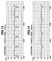
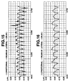
- the unfiltered primary profile curves of the traction contact surfaces of rolling elements (test pieces) 24 and 22 in Examples 25-35 and Comparative Examples 8-11 were measured using the surface roughness tester as used in Example 11, which was set at equal longitudinal and lateral magnifications.
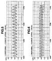
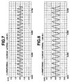
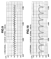
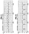
- the unfiltered primary profile curves of the traction contact surfaces of rolling elements (flat test pieces) 24 in Examples 25-35 are shown in Figs. 3-13, while the unfiltered primary profile curves of the traction contact surfaces of rolling elements (flat test pieces) 24 in Comparative Examples 8-11 are shown in Figs. 14-17.
- the unfiltered primary profile curves of the traction contact surfaces of rolling elements (crowning test pieces) 22 in Examples 25-35 and Comparative Examples 8-11 are shown in Fig. 18.
- the rolling contact between both rolling elements (test pieces) 22 and 24 was conducted in oil bath 33 containing a traction oil set at 100°C.
- Nissan CVT fluid KTF-1 Example CVT-exclusive traction fluid
- the vertical load generated by the pressure applied by air cylinder 32 was set at 150 N.
- the maximum bearing pressure was 0.53 GPa in a Hertzian contact and the Hertzian contact ellipse had a minor axis diameter, i.e., a length extending parallel to the rotating direction of rolling elements 22 and 24, of 0.18 mm and a major axis diameter, i.e., a length extending perpendicular to the rotating direction of rolling elements 22 and 24, of 2.8 mm.
- the traction coefficients in Examples 25-35 and Comparative Examples 8-11 were calculated at the slide/roll ratio of 5%.
- Rolling element (flat test piece) 24 was made of JIS SUJ2 steel subjected to quenching-tempering and formed to a cylindrical shape having a diameter of 40 mm, a thickness of 20 mm and a flat cylindrical outer surface. After grinding, the outer surface was subjected to super finishing to form a traction contact surface.
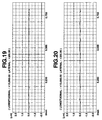
- the unfiltered primary profile curve of the traction contact surface of rolling element (flat test piece) 24 was obtained in the same manner as described in Examples 25-35 and Comparative Examples 8-11. The unfiltered primary profile curve is shown in Fig. 19.
- Rolling element (crowning test piece) 22 was made of JIS SUJ2 steel subjected to quenching-tempering and formed to a cylindrical shape having a diameter of 40 mm, a thickness of 20 mm and a crowning-shaped outer surface having an R (radius) 700 mm. After grinding, the outer surface was subjected to super finishing to form a traction contact surface.
- the unfiltered primary profile curve of the traction contact surface of the traction contact surface of rolling element (crowning test piece) 22 was obtained in the same manner as described in Examples 25-35 and Comparative Examples 8-11.
- the unfiltered primary profile curve is shown in Fig. 20.
- the rolling slipping test and the calculation of traction coefficient were conducted in the same manner as described in Examples 25-35 and Comparative Examples 8-11.
- the production conditions and obtained characteristics of rolling element (flat test piece) 24 in Examples 25-35 and Comparative Examples 8-12 are shown in Table 8.
- the production conditions and obtained characteristics of rolling element (crowning test piece) 22 in Examples 25-35 and Comparative Examples 8-12 are shown in Table 9.
- the traction coefficients obtained in Examples 25-35 and Comparative Examples 8-12 at the slide/roll ratio of 5% also are shown in Table 9.
- Flat test piece Material Heat treatment Machining Tool blade tip shape during groove cutting Abrasive grain diameter during tape lapping ( ⁇ m) Ex. 25 SUJ2 Q,T G,PGC,TL R tip chamfered, R of curv. 0.05mm 2
- the height difference between the top of each top-flat land and the bottom of each recess of the unfiltered primary profile curve in Examples 25-35 was within a range of 0.5-2.5 ⁇ m.
- the radius of curvature at the top portion of each top-flat land of the unfiltered primary profile curve in Examples 25-35 was within a range of 0.1-170 mm.
- the radius of curvature is preferably within a range of 0.8-170 mm, and more preferably within a range of 0.8-10 mm.
- Driven-side rolling elements (flat test pieces) 52 were made of JIS SUJ2 steel subjected to quenching-tempering, JIS SCM420 steel subjected to carburizing-quenching-tempering, JIS SCr420H steel subjected to carburizing-quenching-tempering, JIS SUJ2 steel subjected to carbonitriding-quenching-tempering, respectively, as shown in Table 10.
- Driven-side rolling elements (flat test pieces) 52 were formed to a cylindrical shape having a diameter of 60 mm, a thickness of 10 mm and a flat cylindrical outer surface.
- driven-side rolling elements (fiat test pieces) 52 were subjected to precision groove cutting using polycrystalline c-BN tools having tool blade tips as indicated in Table 10, respectively, to form circumferential grooves and projections between the grooves therein.
- the circumferential grooves were spirally formed along the rotating direction of rolling element (flat test pieces) 52 at equal intervals, after which the projections were machined by tape lapping to form top-flat lands of desired shapes as indicated in Table 10.
- the traction contact surfaces of rolling elements (flat test pieces) 52 were thus obtained.
- the unfiltered primary profile curves of the traction contact surfaces of driven-side rolling elements (flat test pieces) 52 in Examples 35-39 are shown in Figs. 33-36.
- Drive-side rolling elements (crowning test pieces) 54a-54c were made of JIS-SUJ2 steel subjected to quenching-tempering and formed to a cylindrical shape having a diameter of 60 mm, a thickness of 10 mm and a crowning-shaped outer surface having an R (radius) 30 mm. After grinding, the outer surface was finished by tape lapping to form a traction contact surface that had an arithmetical mean roughness Ra of 0.01 ⁇ m. The traction contact surfaces of rolling elements (crowning test pieces) 54a-54c were thus obtained.
- the four-cylinder rolling tester includes rotating shaft 51 supporting driven-side rolling element 52, and three parallel rotating shafts 53a-53c respectively supporting three drive-side rolling elements 54a-54c.
- An outer circumferential surface of driven-side rolling element 52 is urged to be in contact with outer circumferential surfaces of drive-side rolling elements 54a-54c by applying load to one (rotating shaft 53a) of rotating shafts 53a-53c using a pressure-applying mechanism.
- the pressure-applying mechanism includes three arms 55a-55c arranged to form a T-shape and swingably supported in a vertical direction. Two arms 55a and 55b are linearly disposed such that inner ends thereof are mutually overlapped in alignment relation.
- Remaining arm 55c has one end disposed on an upper side of the overlapped inner ends of arms 55a and 55b and an opposite end contacted with pressure-applying portion 57 provided on rotating shaft 53a supporting drive-side rolling element 54a.
- right and left weights 56 as viewed in Fig. 32 act on pressure-applying portion 57 via arms 55a-55c so that drive-side rolling elements 54a-54c are pressed onto the outer circumferential surface of driven-side rolling element 52.
- the traction coefficient can be calculated by measuring the torque generated on rotating shaft 51 supporting driven-side rolling element 52.
- the rotation velocity was 30 m/s
- the shaft rotation number was 10000 rpm
- the slide/roll ratio was 0-3% and a differential was applied to the driven side.
- the maximum bearing pressure was 2.82 GPa in a Hertzian contact and the Hertzian contact ellipse had a minor axis diameter, i.e., a length extending parallel to the rotating direction of rolling elements 52 and 54a-54c, of 1.3 mm and a major axis diameter, i.e., a length extending perpendicular to the rotating direction rolling elements 52 and 54a-54c, of 2.1 mm.
- the oil temperature of Nissan CVT fluid KTF-1 Example 1 (Extroid CVT-exclusive traction fluid) was 150°C.
- Driven-side rolling element (flat test piece) 52 was made of JIS SCM420H steel subjected to carburizing-quenching-tempering and produced in the same manner as indicated in Example 39 in Table 10. The traction contact surface of driven-side rolling element (flat test piece) 52 was thus obtained. The unfiltered primary profile curve of the traction contact surface of driven-side rolling element (flat test piece) 52 is shown in Fig. 40.
- Drive-side rolling elements (crowning test pieces) 54a-54c were made of the same material as that of driven-side rolling element (flat test piece) 52 and produced in the same manner as in Examples 36-39 except that the outer surface was subjected to super finishing after grinding so that the traction contact surface had an arithmetical mean roughness Ra of 0.03 ⁇ m.
- the traction contact surfaces of drive-side rolling elements (crowning test pieces) 54a-54c were thus obtained.
- One of the unfiltered primary profile curves of the traction contact surfaces of drive-side rolling elements (crowning test pieces) 54a-54c is shown in Fig. 41.
- the rolling slipping test and the calculation of traction coefficients were conducted in the same manner as described in Examples 36-39.
- Driven-side rolling element (flat test piece) 52 was made of the same material as that used in Example 40 and produced in the same manner as described in Example 40. The traction contact surface of driven-side rolling element (flat test piece) 52 was thus obtained.
- Drive-side rolling elements (crowning test pieces) 54a-54c were made of the same material as that of driven-side rolling element (flat test piece) 52 and produced in the same manner as described in Example 40 except that the traction contact surface had an arithmetical mean roughness Ra of 0.05 ⁇ m by the super finishing after grinding. The traction contact surfaces of drive-side rolling elements (crowning test pieces) 54a-54c were thus obtained.
- the rolling slipping test and the calculation of traction coefficients were conducted in the same manner as described in Examples 36-39.
- Driven-side rolling element (flat test piece) 52 was made of JIS SUJ2 steel subjected to quenching-tempering and formed to a cylindrical shape having a diameter of 60 mm, a thickness of 10 mm and a flat cylindrical outer surface. After grinding, the outer surface was subjected to super finishing to form a traction contact surface.
- the unfiltered primary profile curve of the traction contact surface of rolling element (flat test piece) 52 is shown in Fig. 38.
- Drive-side rolling elements (crowning test pieces) 54a-54c were made of JIS-SUJ2 steel subjected to quenching-tempering and formed to a cylindrical shape having a diameter of 60 mm, a thickness of 10 mm and a crowning-shaped outer surface having an R 30 mm. After grinding, the outer surface was subjected to super finishing to form a traction contact surface.
- One of the unfiltered primary profile curves of the traction contact surfaces of rolling elements (crowning test pieces) 54a-54c is shown in Fig. 39.
- the rolling slipping test and the calculation of traction coefficients were conducted in the same manner as described in Examples 36-39.
- the good traction coefficients in Examples 36-41 were exhibited and the traction coefficients in Comparative Example 13 which were lower than those in Examples 36-41 were exhibited. Further, it has been found that the ratio of the pitch of the grooves to the major axis diameter of the Hertzian contact ellipse made at the maximum load, which extends perpendicular to the rotating direction of the rolling element, is within the range of 1.2-9%. The ratio of the pitch of the grooves to the major axis diameter of the Hertzian contact ellipse made at the maximum load is preferably within a range of 2.4-6%.
- the ratio of the length of each segment corresponding to the groove to the major axis diameter of the Hertzian contact ellipse made at the maximum load, which extends perpendicular to the rotating direction of the rolling element is within the range of 0.6-2%. Further, it has been found that the ratio of the length of the segment corresponding to the groove to the minor axis diameter of the Hertzian contact ellipse made at the maximum load, which extends parallel to the rotating direction of the rolling element, is within the range of 0.8-3.2%. Furthermore, it has been noted that the recesses extend longer than at least the minor axis diameter of the Hertzian contact ellipse.
- Two driven-side rolling elements (flat test pieces) 52 were produced so as to have a cylindrical shape having a flat cylindrical outer surface.
- One of driven-side rolling elements 52 was subjected to super finishing to form a traction contact surface having an arithmetical mean roughness Ra of 0.08.
- the other of driven-side rolling elements 52 was subjected to super finishing to form the outer surface having an arithmetical mean roughness Ra of 0.1-0.12. After that, the outer surface of the other of driven-side rolling elements 52 was subjected to roller burnishing and observed at intervals with respect to the surface roughness and repeatedly subjected to roller burnishing until the arithmetical mean roughness Ra thereof became 0.08.
- driven-side rolling elements 52 had thus-formed traction contact surface having the arithmetical mean roughness Ra of 0.08.
- Drive-side rolling elements (crowning test pieces) 54a-54c were produced so as to have the crowning-shaped traction contact surface having an R 5 mm and the arithmetical mean roughness Ra of 0.02.
- the rolling slipping test was conducted using the four-cylinder rolling tester shown in Fig. 32 under the following conditions.
- the mean bearing pressure was 0.71 GPa.
- the traction oil temperature was 150°C.
- the rotation velocity was 30 m/s.
- the slide/roll ratio was 3%.
- the traction coefficients in rolling elements (test pieces) 52 and 54a-54c were calculated.
- the traction coefficient in one of driven-side rolling elements (flat test pieces) 52 was 0.059
- the traction coefficient in the other of driven-side rolling elements (flat test pieces) 52 was 0.08. It has been found that the traction coefficient can be improved by forming the traction contact surface smoothened by roller burnishing.
- Example 42 An endurance test of Example 42 was conducted using the four-cylinder rolling tester shown in Fig. 32.
- the test conditions were that the mean bearing pressure was 3.51 GPa, the traction oil temperature was 120°C, the rotation velocity was 30 m/s, and the slide/roll ratio was 3%.
- the life of the other of driven-side rolling elements (flat test pieces) 52 was 1.4 times the life of one of driven-side rolling elements (flat test pieces) 52.
- Figs. 21, 22, 23A and 23B show one embodiment of the rolling element of the traction drive rotary assembly of the invention and a process for the rolling element, according to the present invention.
- rolling element 11 is in the form of a cylinder an outer circumferential surface of which is formed into a traction contact surface.
- Fig. 23A shows a schematic profile of the outer circumferential surface of rolling element 11 and
- Fig.23B shows a schematic profile of the traction contact surface of rolling element 11.
- recesses 12 having a depth D are formed at equal intervals in the outer circumferential surface of rolling element 11.
- the depth D is 10 ⁇ m or less.
- Alternately arranged recesses 12 and projections 14 are thus formed.
- one end of rolling element 11 is rotatably supported by chuck 21A of main pillow block 21, and the other end of rolling element 11 is rotatably supported by center 22A of tail stock 22.
- Tool 23 for cutting or grinding is fed at a constant speed in the direction of a center axis of rolling element 11, while rotating rolling element 11 around the center axis.
- recesses 12 are formed in a spiral groove shape in the outer circumferential surface of rolling element 11.
- a polycrystalline c-BN tool having a sharp blade tip end (e.g., R (radius) 50 ⁇ m), diamond tool or coating tool covered with TiN or the like, may be used as tool 23.
- the blade tip end of tool 23 may be of at least one shape selected from a single R (radius), a trapezoidal shape, a V-shape and a complex R.
- Tool 23 may have a width of 4-150 ⁇ m at a location spaced from the blade tip end by 0.5-2.5 ⁇ m.
- Tool 23 also may have a round blade tip end having R of 0.2 mm or less.
- Figs. 23A and 23B denote the profile of the outer circumferential surface before recesses 12 and projections 14 are formed.
- top-flat lands 13 such that the height difference H shown in Fig. 23B, between recesses 12 and top-flat lands 13 is 0.5-2.5 ⁇ m, and preferably 0.8-1.2 ⁇ m.
- lapping film 26 having aluminum oxide particles having a particle diameter of 3 ⁇ m is stretched over a pair of feed rollers 24 and 25.
- the outer circumferential surface of rolling element 11 is brought into contact with lapping film 26, and at the same time lapping film 26 is pressed against rolling element 11 by back shoe 27.
- Rolling element 11 is rotated around the center axis as indicated by the arrows in Fig.
- each land 13 may of a flat profile shape or a crowning profile shape on one side thereof. If necessary, the profile shape of top-flat lands 13 can be suitably adjusted by reversing the feeding direction of lapping film 26 or the rotating direction of rolling element 11.
- recesses 12 and top-flat lands 13 are continuously formed along the direction of rotation of rolling element 11, namely, the circumferential direction thereof, and recesses 12 and top-flat lands 13 are alternately formed at equal intervals.
- the height difference between recesses 12 and top-flat lands 13, is 0.5-2.5 ⁇ m.
- Recesses 12 are formed such that, with respect to center line C shown in Fig. 23B, which is separated into segments by crossing with the unfiltered primary profile curve, a ratio of a total length of the segments corresponding to the recesses 12 to a reference length of center line C, is within the range of 15-60%.
- Center line C is a line drawn at an average height determined by integrating the unfiltered primary profile curve in the direction of length.
- recesses 12 are formed such that pitch P thereof shown in Fig. 23B is 10-150 ⁇ m and length (width) W thereof shown in Fig. 23B is 10-40 ⁇ m.
- Pitch P is a length extending between bottoms of adjacent recesses 12 along center line C.
- Length W is a length of the segment of center line C which corresponds to recess 12 of the unfiltered primary profile curve.
- Top-flat lands 13 are formed such that the top portions have a ten-point mean roughness Rz of 100 nm or less, and more preferably 40 nm or less.
- recesses 12 are formed in a spiral groove shape in advance of the following grinding.
- the formation of spiral groove-shaped recesses 12 can facilitate crushing and dropping of abrasive particles along with discharge of cuttings during the subsequent grinding step so that the grinding also can be conducted efficiently with a good cutting edge at all times.
- the trapezoidal lands 13 having chamfered corners and crowning-shaped lands 13 can be formed with high accuracy without being affected by the magnitude of the intervals between recesses 12.
- Figs. 24 and 25 illustrate another embodiment of the rolling element and a process therefor, according to the present invention.
- the outer circumferential surface of rolling element 11 is formed by electrolytic polishing so as to have a ten-point mean roughness Rz of 100 nm or less, and preferably 40 nm or less.
- rolling element 11 is rotatably supported by chuck 21A of main pillow block 21 and center 22A of tail stock 22 and disposed on the anode side.
- Electrolyte 30 is supplied to the outer circumferential surface of rolling element 11 from electrolyte supply unit 29 with grindstone 28 on the cathode side.
- the outer circumferential surface of rolling element 11 thus is subjected to mirror polishing. In this case, the surface roughness of the outer circumferential surface of rolling element 11 is measured with an interatomic microscope.
- top-flat lands 13 to be formed in the following recess-forming step have top portions having a ten-point mean roughness Rz of not more than 100 nm or not more than 40 nm.
- recesses 12 are formed in the outer circumferential surface of rolling element 11.
- Recesses 12 are formed at equal intervals in the direction of the center axis of rolling element 11 using, for example, thin-blade grindstone 31 having a generally circular arc shape in section, such that recesses 12 have a depth of 0.5-2.5 ⁇ m.
- Rolling element 11 and grindstone 31 are moved relative to each other in the direction of the center axis of rolling element 11 and in the direction perpendicular to the center axis, while rolling element 11 is rotated around the axis of rotation with chuck 21A of main pillow block 21 and center 22A of tail stock 22.
- the generally circular arc shape may include arc portions of two circles having different centers and joined together.
- each recess 12 is in the form of a groove continuously extending in the circumferential direction of rolling element 11.
- Recess 12 may also be in the form of a spiral groove.
- the traction contact surface having alternately arranged recesses 12 and top-flat lands 13 thus is formed in rolling element 11.
- Rolling element 11 of the traction drive rotary assembly thus can be obtained in this embodiment, which has excellent traction characteristics as well as the above-described embodiment does.
- Figs. 26A and 26B show still another embodiment of the rolling element and a process therefor, according to the present invention.
- recesses 12 and top-flat lands 13 are simultaneously formed in a spiral shape in an outer circumferential surface of rolling element 11 using tool 32 having cutting blades 32A and 32B shown in Fig. 26B, respectively corresponding to recesses 12 and top-flat lands 13, while rotating rolling element 11 around the axis of rotation with chuck 21A of main pillow block 21 and center 22A of tail stock 22.
- a step S between cutting blades 32A and 32B is 0.5-2.5 ⁇ m and extends in a direction perpendicular to the center axis of rolling element 11.
- rolling element 11 having excellent traction characteristics can be obtained as described in the above embodiments and recesses 12 and top-flat lands 13 having a predetermined dimensional relationship can be efficiently formed in a short period of time.
- Figs. 27 and 28 show still another embodiment of the rolling element and a process therefor, according to the present invention.
- Rolling element 11 has an outer circumferential surface having an arcuate cross-section recessed toward the center axis of rolling element 11. As shown in Fig. 27, rolling element 11 is rotatably supported on both sides thereof by a pair of holders 33 and 34. Recesses 12 are formed in a spiral groove shape in the outer circumferential surface of rolling element 11 using a cutting or grinding tool 35. Grinding tool 35 and rolling element 11 are relatively moved in the direction of the center axis of rolling element 11 with keeping the contact therebetween, while rolling element 11 is rotated around the axis of rotation. To this end, projections 14 are formed between recesses 12 on the outer circumferential surface of rolling element 11. Subsequently, projections 14 are subjected to super finishing using elastic grindstone 36 shown in Fig.
- rolling element 11 produced in this embodiment can exhibit excellent traction characteristics.
- Recesses 12 may be formed by shot peening, grinding, cutting, blasting, laser machining or etching.
- Top-flat lands 13 may be formed by lapping, mirror polishing, super finishing, cutting, grinding, electrolytic polishing or roller burnishing.
- top-flat lands 13 may be formed using a fixed abrasive grain tool, such as a grindstone or lapping film, having abrasive grains of a mean grain diameter of 9 ⁇ m or less, or using an elastic grindstone bound with rubber or an elastic grindstone bound with a resin such as epoxy resin or PVA, having a mean abrasive grain diameter of 30 ⁇ m or less.
- Figs. 29A-31C show examples of shapes of recesses 12 and top-flat lands 13 of the unfiltered primary profile curve of the traction contact surface of rolling element 11.
- Examples of shapes of top-flat lands 13 located higher than center line C include a generally trapezoidal shape shown in Fig. 29A, a generally trapezoidal shape with rounded corners shown in Fig. 29B, a generally elliptic arc or sinusoidal shape shown in Fig. 29C, and a generally triangular shape with a rounded apex shown in Fig. 30A.
- Examples of shapes of top-flat lands 13 also include a generally trapezoidal shape with chamfered corners shown in Fig. 31A, a generally crowning shape shown in Fig. 31B, and the one-sided crowning shape formed by lapping shown in Fig. 31C.
- the height difference H between the top of top-flat land 13 and the bottom of recess 12 of the unfiltered primary profile curve is 0.5-2.5 ⁇ m, and preferably 0.8-1.2 ⁇ m, and also preferably 2.0-2.5 ⁇ m.
- the ratio of a total length of the segments corresponding to recesses 12 to a reference length of center line C is within a range of 15-60%, preferably 30-57%, more preferably 25-40% and further more preferably 27-30%.
- the pitch P of recesses 12 along center line C is within a range of 10-150 ⁇ m, and preferably 40-120 ⁇ m.
- top-flat lands 13 The surface roughness of top portions of top-flat lands 13 is within a range of Rz 100 nm or less, and preferably Rz 40 nm or less.
- the length (width) W of recess 12, namely, a length of the segment of center line C, which corresponds to recess 12, is 10-40 ⁇ m.
Landscapes
- Engineering & Computer Science (AREA)
- General Engineering & Computer Science (AREA)
- Mechanical Engineering (AREA)
- Friction Gearing (AREA)
- Rolling Contact Bearings (AREA)
Applications Claiming Priority (6)
| Application Number | Priority Date | Filing Date | Title |
|---|---|---|---|
| JP25257499 | 1999-09-07 | ||
| JP25257499 | 1999-09-07 | ||
| JP2000147364 | 2000-05-19 | ||
| JP2000147364 | 2000-05-19 | ||
| JP2000258160 | 2000-08-28 | ||
| JP2000258160A JP3664058B2 (ja) | 1999-09-07 | 2000-08-28 | トラクションドライブ用転動体およびその製造方法 |
Publications (3)
| Publication Number | Publication Date |
|---|---|
| EP1083368A2 true EP1083368A2 (fr) | 2001-03-14 |
| EP1083368A3 EP1083368A3 (fr) | 2001-04-11 |
| EP1083368B1 EP1083368B1 (fr) | 2003-12-17 |
Family
ID=27334134
Family Applications (1)
| Application Number | Title | Priority Date | Filing Date |
|---|---|---|---|
| EP00119126A Expired - Lifetime EP1083368B1 (fr) | 1999-09-07 | 2000-09-04 | Ensemble rotatif d'une variateur de vitesse à friction et procédé de fabrication des éléments de roulement de tel ensemble |
Country Status (6)
| Country | Link |
|---|---|
| US (2) | US6629906B1 (fr) |
| EP (1) | EP1083368B1 (fr) |
| JP (1) | JP3664058B2 (fr) |
| KR (1) | KR100389247B1 (fr) |
| CN (1) | CN1209563C (fr) |
| DE (1) | DE60007244T2 (fr) |
Cited By (5)
| Publication number | Priority date | Publication date | Assignee | Title |
|---|---|---|---|---|
| NL1018189C2 (nl) * | 2001-05-31 | 2002-12-03 | Skf Ab | Transmissie met wentelaandrijving. |
| EP1167819A3 (fr) * | 2000-06-29 | 2007-05-23 | Nissan Motor Company, Limited | Transmission continue de vitesse du type torique |
| US7465249B2 (en) | 2004-10-26 | 2008-12-16 | Nsk Ltd. | Toroidal type continuously variable transmission |
| EP1235002A3 (fr) * | 2001-02-21 | 2009-04-22 | Nissan Motor Company, Limited | Ensemble rotatif d'un variateur de vitesse |
| CN110497206A (zh) * | 2019-07-03 | 2019-11-26 | 吴国烘 | 一种电路板成型加工机 |
Families Citing this family (31)
| Publication number | Priority date | Publication date | Assignee | Title |
|---|---|---|---|---|
| JP3555844B2 (ja) | 1999-04-09 | 2004-08-18 | 三宅 正二郎 | 摺動部材およびその製造方法 |
| JP3664058B2 (ja) * | 1999-09-07 | 2005-06-22 | 日産自動車株式会社 | トラクションドライブ用転動体およびその製造方法 |
| JP4196636B2 (ja) * | 2002-10-17 | 2008-12-17 | 日産自動車株式会社 | トラクションドライブ用転動体の製造方法 |
| JP2004138165A (ja) * | 2002-10-18 | 2004-05-13 | Nissan Motor Co Ltd | トラクションドライブ用ディスク及びその製造方法 |
| US6969198B2 (en) | 2002-11-06 | 2005-11-29 | Nissan Motor Co., Ltd. | Low-friction sliding mechanism |
| JP3891433B2 (ja) | 2003-04-15 | 2007-03-14 | 日産自動車株式会社 | 燃料噴射弁 |
| EP1479946B1 (fr) | 2003-05-23 | 2012-12-19 | Nissan Motor Co., Ltd. | Piston pour un moteur à combustion interne |
| EP1482190B1 (fr) | 2003-05-27 | 2012-12-05 | Nissan Motor Company Limited | Elément de roulement |
| JP2004360649A (ja) | 2003-06-06 | 2004-12-24 | Nissan Motor Co Ltd | エンジン用ピストンピン |
| JP4863152B2 (ja) | 2003-07-31 | 2012-01-25 | 日産自動車株式会社 | 歯車 |
| EP1666573B1 (fr) | 2003-08-06 | 2019-05-15 | Nissan Motor Company Limited | Mecanisme coulissant a faible frottement et procede de reduction de frottement |
| JP2005054617A (ja) | 2003-08-08 | 2005-03-03 | Nissan Motor Co Ltd | 動弁機構 |
| JP4973971B2 (ja) | 2003-08-08 | 2012-07-11 | 日産自動車株式会社 | 摺動部材 |
| DE602004008547T2 (de) | 2003-08-13 | 2008-05-21 | Nissan Motor Co., Ltd., Yokohama | Struktur zur Verbindung von einem Kolben mit einer Kurbelwelle |
| JP4539205B2 (ja) | 2003-08-21 | 2010-09-08 | 日産自動車株式会社 | 冷媒圧縮機 |
| US7771821B2 (en) | 2003-08-21 | 2010-08-10 | Nissan Motor Co., Ltd. | Low-friction sliding member and low-friction sliding mechanism using same |
| EP1508611B1 (fr) | 2003-08-22 | 2019-04-17 | Nissan Motor Co., Ltd. | Boîte de vitesse comprenant une composition d`huile de transmission |
| JP4851105B2 (ja) * | 2005-03-07 | 2012-01-11 | バンドー化学株式会社 | ベルト伝動装置 |
| US8062094B2 (en) * | 2005-06-29 | 2011-11-22 | Deere & Company | Process of durability improvement of gear tooth flank surface |
| JP2007016851A (ja) * | 2005-07-06 | 2007-01-25 | Ntn Corp | トリポード型等速自在継手 |
| US9188206B2 (en) | 2007-06-06 | 2015-11-17 | Nsk Ltd. | Toroidal continuously variable transmission |
| JP2009085332A (ja) * | 2007-09-28 | 2009-04-23 | Nsk Ltd | トロイダル型無段変速機 |
| US8434340B2 (en) * | 2008-12-23 | 2013-05-07 | Barnes Group, Inc. | Method for forming a stamped metal part |
| KR20150084935A (ko) * | 2013-01-18 | 2015-07-22 | 쟈트코 가부시키가이샤 | 멀티 디스크 변속기 |
| US10023824B2 (en) | 2013-04-11 | 2018-07-17 | Afton Chemical Corporation | Lubricant composition |
| EP3253900B1 (fr) | 2015-02-04 | 2020-08-12 | Sikorsky Aircraft Corporation | Procédés et processus de formation d'engrenages |
| DE102016214934A1 (de) * | 2016-08-11 | 2018-02-15 | Schaeffler Technologies AG & Co. KG | Kegelscheibeneinheit für ein Kegelscheibengetriebe sowie Verfahren zur Herstellung einer Kegelscheibeneinheit |
| CN106438891B (zh) * | 2016-10-31 | 2019-09-10 | 西华大学 | 一种牵引式cvt无自旋结构设计方法 |
| CN107179101B (zh) * | 2017-05-27 | 2019-03-19 | 郑州磨料磨具磨削研究所有限公司 | 一种砂轮表面粗糙度和磨粒分布状态的检测及评价方法 |
| KR102179251B1 (ko) * | 2019-12-24 | 2020-11-16 | 삼익키리우 (주) | 자동차용 브레이크 디스크의 제조방법 |
| CN114426039B (zh) * | 2022-03-14 | 2023-06-30 | 浙江师范大学 | 一种基于城轨列车车轮踏面的点云数据处理方法 |
Citations (1)
| Publication number | Priority date | Publication date | Assignee | Title |
|---|---|---|---|---|
| JPS62251559A (ja) | 1986-04-23 | 1987-11-02 | Nissan Motor Co Ltd | トロイダル型無段変速機 |
Family Cites Families (17)
| Publication number | Priority date | Publication date | Assignee | Title |
|---|---|---|---|---|
| US2020677A (en) * | 1933-02-09 | 1935-11-12 | Erban Patents Corp | Friction gear |
| US2847861A (en) * | 1953-06-23 | 1958-08-19 | Zenas V Weisel | Variable speed transmission |
| CA1277310C (fr) * | 1985-11-29 | 1990-12-04 | Toshiyuki Tsubouchi | Fluide actif pour organe de traction |
| JPH05340456A (ja) * | 1992-06-08 | 1993-12-21 | Nippon Seiko Kk | 動力伝達装置 |
| JPH07286649A (ja) | 1994-04-18 | 1995-10-31 | Nippon Seiko Kk | トロイダル形無段変速機 |
| JPH08296709A (ja) * | 1995-04-26 | 1996-11-12 | Nissan Motor Co Ltd | 高面圧転動体 |
| JPH09210162A (ja) * | 1996-01-31 | 1997-08-12 | Ntn Corp | 遊星ローラ式動力伝達装置 |
| JP3470741B2 (ja) * | 1996-03-26 | 2003-11-25 | 日産自動車株式会社 | トロイダル式無段変速機用転動体およびその製造方法 |
| JPH10231908A (ja) * | 1997-02-19 | 1998-09-02 | Nissan Motor Co Ltd | トロイダル式無段変速機用転動体およびその製造方法 |
| US5863873A (en) * | 1997-04-08 | 1999-01-26 | Exxon Chemical Patents Inc | Fuel economy additive and lubricant composition containing same |
| US6174257B1 (en) | 1997-07-04 | 2001-01-16 | Nsk Ltd. | Toroidal type continuously variable transmission |
| DE19829631B4 (de) * | 1997-07-04 | 2006-01-19 | Nsk Ltd. | Stufenlos verstellbares Toroidgetriebe |
| JP2000065069A (ja) * | 1998-08-25 | 2000-03-03 | Nippon Seiko Kk | 玉軸受 |
| JP3870592B2 (ja) * | 1999-01-11 | 2007-01-17 | 日本精工株式会社 | ハーフトロイダル型無段変速機 |
| JP3664058B2 (ja) * | 1999-09-07 | 2005-06-22 | 日産自動車株式会社 | トラクションドライブ用転動体およびその製造方法 |
| JP3630297B2 (ja) * | 2000-03-23 | 2005-03-16 | 日産自動車株式会社 | 自動車用トロイダル式無段変速機 |
| JP3736619B2 (ja) * | 2000-06-29 | 2006-01-18 | 日産自動車株式会社 | トロイダル型無段変速機 |
-
2000
- 2000-08-28 JP JP2000258160A patent/JP3664058B2/ja not_active Expired - Fee Related
- 2000-09-04 DE DE60007244T patent/DE60007244T2/de not_active Expired - Lifetime
- 2000-09-04 EP EP00119126A patent/EP1083368B1/fr not_active Expired - Lifetime
- 2000-09-07 KR KR10-2000-0052957A patent/KR100389247B1/ko not_active Expired - Fee Related
- 2000-09-07 CN CNB001268635A patent/CN1209563C/zh not_active Expired - Fee Related
- 2000-09-07 US US09/657,361 patent/US6629906B1/en not_active Expired - Lifetime
-
2003
- 2003-04-30 US US10/425,917 patent/US6736036B2/en not_active Expired - Lifetime
Patent Citations (1)
| Publication number | Priority date | Publication date | Assignee | Title |
|---|---|---|---|---|
| JPS62251559A (ja) | 1986-04-23 | 1987-11-02 | Nissan Motor Co Ltd | トロイダル型無段変速機 |
Cited By (7)
| Publication number | Priority date | Publication date | Assignee | Title |
|---|---|---|---|---|
| EP1167819A3 (fr) * | 2000-06-29 | 2007-05-23 | Nissan Motor Company, Limited | Transmission continue de vitesse du type torique |
| EP1235002A3 (fr) * | 2001-02-21 | 2009-04-22 | Nissan Motor Company, Limited | Ensemble rotatif d'un variateur de vitesse |
| NL1018189C2 (nl) * | 2001-05-31 | 2002-12-03 | Skf Ab | Transmissie met wentelaandrijving. |
| WO2002097304A1 (fr) * | 2001-05-31 | 2002-12-05 | Ab Skf | Transmission rotative |
| US7465249B2 (en) | 2004-10-26 | 2008-12-16 | Nsk Ltd. | Toroidal type continuously variable transmission |
| CN110497206A (zh) * | 2019-07-03 | 2019-11-26 | 吴国烘 | 一种电路板成型加工机 |
| CN110497206B (zh) * | 2019-07-03 | 2022-07-01 | 江门市创轩五金电子有限公司 | 一种电路板成型加工机 |
Also Published As
| Publication number | Publication date |
|---|---|
| US6736036B2 (en) | 2004-05-18 |
| KR100389247B1 (ko) | 2003-06-27 |
| US6629906B1 (en) | 2003-10-07 |
| CN1209563C (zh) | 2005-07-06 |
| US20030200846A1 (en) | 2003-10-30 |
| JP2002039306A (ja) | 2002-02-06 |
| EP1083368A3 (fr) | 2001-04-11 |
| KR20010082519A (ko) | 2001-08-30 |
| DE60007244D1 (de) | 2004-01-29 |
| JP3664058B2 (ja) | 2005-06-22 |
| CN1287234A (zh) | 2001-03-14 |
| EP1083368B1 (fr) | 2003-12-17 |
| DE60007244T2 (de) | 2004-09-23 |
Similar Documents
| Publication | Publication Date | Title |
|---|---|---|
| US6629906B1 (en) | Traction drive rotary assembly and process for producing rolling element thereof | |
| EP1136724B1 (fr) | Transmission continue du type torique pour véhicules | |
| US7958635B2 (en) | Process for producing a pulley for a continuously variable belt drive transmission | |
| US9188206B2 (en) | Toroidal continuously variable transmission | |
| WO2007125927A1 (fr) | Procede de production de bague exterieure utilisant une unite de roulement | |
| JP2002089644A (ja) | トロイダル型無段変速機 | |
| KR100816576B1 (ko) | 연속가변형 트랜스미션용 전동판의 제조방법과 장치 | |
| US6881126B2 (en) | Traction drive rolling element and method of forming the same | |
| JP5056591B2 (ja) | トロイダル型無段変速機 | |
| EP1235002B1 (fr) | Ensemble rotatif d'un variateur de vitesse | |
| EP2811204A1 (fr) | Transmission à variation continue de type toroïdal | |
| CN113108033B (zh) | 带式无级变速机的制造方法 | |
| JP2001227610A (ja) | トロイダル型無段変速機用ディスクとその加工方法 | |
| JP2001304267A (ja) | 摺動部材およびその製造方法 | |
| JP3748067B2 (ja) | トラクションドライブ用転動体 | |
| JP5381797B2 (ja) | トロイダル型無段変速機の製造方法 | |
| JP2002039303A (ja) | トラクションドライブ装置および動力伝達用転動体の溝加工方法 | |
| WO2021254663A1 (fr) | Procédé de fabrication d'un segment transversal pour une courroie d'entraînement | |
| JP2003278869A (ja) | トラクションドライブ用転動体およびその製造方法 | |
| JP2000170863A (ja) | トラクションドライブ用転動体 | |
| JP2011185330A (ja) | トロイダル型無段変速機のローラの製造装置 | |
| JP2013202726A (ja) | トロイダル型無段変速機の製造方法 | |
| JPS6088245A (ja) | 無段変速機用ベルトブロツクの製造方法 |
Legal Events
| Date | Code | Title | Description |
|---|---|---|---|
| PUAI | Public reference made under article 153(3) epc to a published international application that has entered the european phase |
Free format text: ORIGINAL CODE: 0009012 |
|
| PUAL | Search report despatched |
Free format text: ORIGINAL CODE: 0009013 |
|
| 17P | Request for examination filed |
Effective date: 20000904 |
|
| AK | Designated contracting states |
Kind code of ref document: A2 Designated state(s): DE FR GB |
|
| AX | Request for extension of the european patent |
Free format text: AL;LT;LV;MK;RO;SI |
|
| AK | Designated contracting states |
Kind code of ref document: A3 Designated state(s): AT BE CH CY DE DK ES FI FR GB GR IE IT LI LU MC NL PT SE |
|
| AX | Request for extension of the european patent |
Free format text: AL;LT;LV;MK;RO;SI |
|
| RIC1 | Information provided on ipc code assigned before grant |
Free format text: 7F 16H 15/38 A, 7F 16H 55/34 B |
|
| RIN1 | Information on inventor provided before grant (corrected) |
Inventor name: USHIJIMA, KENSHI Inventor name: OOTA, MINORU Inventor name: CHIBA, NOBUTAKA Inventor name: OMATA, MASAHIRO Inventor name: WATANABE, JUN Inventor name: KANO, MAKOTO Inventor name: UEDA, HIROO Inventor name: NANBU, TOSHIKAZU |
|
| AKX | Designation fees paid |
Free format text: DE FR GB |
|
| 17Q | First examination report despatched |
Effective date: 20021211 |
|
| GRAH | Despatch of communication of intention to grant a patent |
Free format text: ORIGINAL CODE: EPIDOS IGRA |
|
| GRAS | Grant fee paid |
Free format text: ORIGINAL CODE: EPIDOSNIGR3 |
|
| GRAA | (expected) grant |
Free format text: ORIGINAL CODE: 0009210 |
|
| AK | Designated contracting states |
Kind code of ref document: B1 Designated state(s): DE FR GB |
|
| REG | Reference to a national code |
Ref country code: GB Ref legal event code: FG4D |
|
| REF | Corresponds to: |
Ref document number: 60007244 Country of ref document: DE Date of ref document: 20040129 Kind code of ref document: P |
|
| ET | Fr: translation filed | ||
| PLBE | No opposition filed within time limit |
Free format text: ORIGINAL CODE: 0009261 |
|
| STAA | Information on the status of an ep patent application or granted ep patent |
Free format text: STATUS: NO OPPOSITION FILED WITHIN TIME LIMIT |
|
| 26N | No opposition filed |
Effective date: 20040920 |
|
| REG | Reference to a national code |
Ref country code: FR Ref legal event code: PLFP Year of fee payment: 17 |
|
| REG | Reference to a national code |
Ref country code: FR Ref legal event code: PLFP Year of fee payment: 18 |
|
| REG | Reference to a national code |
Ref country code: FR Ref legal event code: PLFP Year of fee payment: 19 |
|
| PGFP | Annual fee paid to national office [announced via postgrant information from national office to epo] |
Ref country code: DE Payment date: 20180821 Year of fee payment: 19 Ref country code: FR Payment date: 20180712 Year of fee payment: 19 |
|
| PGFP | Annual fee paid to national office [announced via postgrant information from national office to epo] |
Ref country code: GB Payment date: 20180829 Year of fee payment: 19 |
|
| REG | Reference to a national code |
Ref country code: DE Ref legal event code: R119 Ref document number: 60007244 Country of ref document: DE |
|
| PG25 | Lapsed in a contracting state [announced via postgrant information from national office to epo] |
Ref country code: DE Free format text: LAPSE BECAUSE OF NON-PAYMENT OF DUE FEES Effective date: 20200401 |
|
| GBPC | Gb: european patent ceased through non-payment of renewal fee |
Effective date: 20190904 |
|
| PG25 | Lapsed in a contracting state [announced via postgrant information from national office to epo] |
Ref country code: GB Free format text: LAPSE BECAUSE OF NON-PAYMENT OF DUE FEES Effective date: 20190904 Ref country code: FR Free format text: LAPSE BECAUSE OF NON-PAYMENT OF DUE FEES Effective date: 20190930 |