EP1083619A2 - Ensemble de batteries - Google Patents
Ensemble de batteries Download PDFInfo
- Publication number
- EP1083619A2 EP1083619A2 EP00402494A EP00402494A EP1083619A2 EP 1083619 A2 EP1083619 A2 EP 1083619A2 EP 00402494 A EP00402494 A EP 00402494A EP 00402494 A EP00402494 A EP 00402494A EP 1083619 A2 EP1083619 A2 EP 1083619A2
- Authority
- EP
- European Patent Office
- Prior art keywords
- battery cell
- leakage
- battery pack
- battery
- electrolyte solution
- Prior art date
- Legal status (The legal status is an assumption and is not a legal conclusion. Google has not performed a legal analysis and makes no representation as to the accuracy of the status listed.)
- Granted
Links
Images




Classifications
-
- H—ELECTRICITY
- H01—ELECTRIC ELEMENTS
- H01M—PROCESSES OR MEANS, e.g. BATTERIES, FOR THE DIRECT CONVERSION OF CHEMICAL ENERGY INTO ELECTRICAL ENERGY
- H01M10/00—Secondary cells; Manufacture thereof
- H01M10/42—Methods or arrangements for servicing or maintenance of secondary cells or secondary half-cells
- H01M10/48—Accumulators combined with arrangements for measuring, testing or indicating the condition of cells, e.g. the level or density of the electrolyte
-
- H—ELECTRICITY
- H01—ELECTRIC ELEMENTS
- H01M—PROCESSES OR MEANS, e.g. BATTERIES, FOR THE DIRECT CONVERSION OF CHEMICAL ENERGY INTO ELECTRICAL ENERGY
- H01M50/00—Constructional details or processes of manufacture of the non-active parts of electrochemical cells other than fuel cells, e.g. hybrid cells
- H01M50/50—Current conducting connections for cells or batteries
- H01M50/572—Means for preventing undesired use or discharge
- H01M50/574—Devices or arrangements for the interruption of current
-
- H—ELECTRICITY
- H01—ELECTRIC ELEMENTS
- H01M—PROCESSES OR MEANS, e.g. BATTERIES, FOR THE DIRECT CONVERSION OF CHEMICAL ENERGY INTO ELECTRICAL ENERGY
- H01M10/00—Secondary cells; Manufacture thereof
- H01M10/42—Methods or arrangements for servicing or maintenance of secondary cells or secondary half-cells
- H01M10/4228—Leak testing of cells or batteries
-
- Y—GENERAL TAGGING OF NEW TECHNOLOGICAL DEVELOPMENTS; GENERAL TAGGING OF CROSS-SECTIONAL TECHNOLOGIES SPANNING OVER SEVERAL SECTIONS OF THE IPC; TECHNICAL SUBJECTS COVERED BY FORMER USPC CROSS-REFERENCE ART COLLECTIONS [XRACs] AND DIGESTS
- Y02—TECHNOLOGIES OR APPLICATIONS FOR MITIGATION OR ADAPTATION AGAINST CLIMATE CHANGE
- Y02E—REDUCTION OF GREENHOUSE GAS [GHG] EMISSIONS, RELATED TO ENERGY GENERATION, TRANSMISSION OR DISTRIBUTION
- Y02E60/00—Enabling technologies; Technologies with a potential or indirect contribution to GHG emissions mitigation
- Y02E60/10—Energy storage using batteries
Definitions
- This invention relates to a battery pack having one or more battery cells enclosed therein. More particularly, it relates to a battery pack in which, on occurrence of liquid leakage in an internal battery cell, such liquid leakage is detected to prohibit the progression of malfunctions caused by such liquid leakage.
- the battery pack used as a driving power source for a portable electrical equipment, such as a personal computer, portable telephone or a video camera, referred to below simply as a main equipment, includes one or more battery cells and a control circuit, in its inside, these battery cells and the control circuit being interconnected by a complex interconnection.
- leakage of the electrolyte solution, sealed in the battery cell is likely to occur if a shock is applied from outside to the battery pack due to fall or collision, if the exterior of the battery cell is rusted due to moisture intruded into the inside of the battery pack, or if the junction of the exterior in the vicinity of the positive electrode of the battery cell is deteriorated or punched. If such leakage of the electrolyte solution occurs in one of the battery cells in the battery pack, the electrolyte solution flows into and is spread in the inside of the battery pack to become attached to the interconnection or to a substrate of the control circuit.
- the electrolyte solution tends to become attached to the interconnection or to a substrate of the control circuit and, after lapse of a certain time interval, metals such as copper, iron, aluminum or nickel of the interconnection or the substrate are dissolved into the electrolyte solution.
- the resistance of the portion to which the electrolyte solution has attached is lowered to form a new electrically conductive line of a certain resistance value.
- the resistance of the portions to which the electrolyte solution has attached may, for example, be on the order of 1 to 10 ⁇ .
- the electrically conductive line produced by leakage of the electrolyte solution is connected to both the positive and negative electrodes.
- the voltage of the battery cell is applied to the electrically conductive line so that the current flows therein to evolve heat to raise the cell temperature.
- the voltage of the battery cell is 4V and the resistance of the electrically conductive is 1 ⁇
- the current of 1A flows in the electrically conductive line to evolve the heat of 4W.
- the temperature of the electrically conductive line is raised gradually to reach 200°C or higher, accidents due to leakage of the electrolyte solution, such as filming or firing, occur in the electrically conductive line.
- the heat of the electrically conductive line is transmitted to the battery cell arranged in its vicinity, such that the risk of fuming or firing occurs even in the battery cell the terminals of which are not interconnected by the electrically conductive line.
- the synthetic resin separator isolating the positive and negative electrodes from each other in the battery cell is dissolved to short the positive and negative electrodes to cause internal shorting to evolve heat and consequent fuming or firing thus leading to accidents ascribable to leakage.
- the insulating paper sheet is used, it is difficult to absorb the leaked electrolyte solution completely.
- the metal portions are coated with e.g., an adhesive, such a phenomenon occurs in which the adhesive is first dissolved in the electrolyte solution before the metal portions are dissolved.
- a battery pack including a battery cell, leakage detection means for detecting the leakage of an electrolyte solution of the battery cell, current breaking means for electrically interrupting the current line between the battery cell and external terminals on occurrence of leakage of the electrolyte solution in the battery cell and discharging means having the function of self-discharging the battery cell.
- the battery pack according to the present invention there is provided a function of disconnecting the connection line between the external terminals and the battery cell on detection of leakage of the electrolyte solution, so that the battery pack in the unusual state is necessarily unusable to prevent the accident due to the leakage from progressing to prevent unusual heating and accidents of ignition or fuming ascribable to such heating.
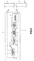
- Fig. 1 illustrates a schematic structure of a battery pack.
- Fig.2 is a block diagram showing a schematic structure of a battery pack.
- Fig.3 illustrates a schematic structure of a leakage detector.
- Figs.4a and 4b illustrate the structure of the leakage detector, Fig.4a being a plan view of a leakage detection unit and Fig.4b being a longitudinal cross-sectional view showing a modification of the leakage detector.
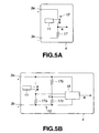
- Fig.5a is a circuit diagram showing a structure of a leakage detector and Fig.5b is a circuit diagram showing another structure of a leakage detector.
- Fig.6a is a circuit diagram showing a structure of a current breaker and Fig.6b is a circuit diagram showing another structure of a current breaker.
- Fig.7a is a circuit diagram showing a structure of a discharging device
- Fig.7b is a circuit diagram showing another structure of a discharging device
- Fig.7c is a circuit diagram showing yet another structure of a discharging device
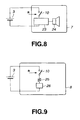
- Fig.8 is a circuit diagram showing a structure of an alarm sound generating device.
- Fig.9 is a circuit diagram showing a structure of a light emitting device.
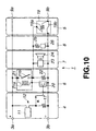
- Fig.10 is a circuit diagram showing a specified structure of a battery pack.
- the battery cell 3 used is a lithium ion secondary cell, only by way of an example.
- secondary batteries such as a nickel-cadmium cell, a nickel-hydrogen cell, a lithium ion cell, a lithium polymer cell or a lead cell, or primary batteries, such as a manganese battery, an alkali battery or a lithium battery, may also be used.
- the leakage detection unit 4 has the function of detecting possible leakage occurring in the battery cell 3 accommodated in the battery pack 1.
- the leakage detection unit 4 includes a leakage detector 11 and a leakage verification unit 12, as shown in Fig.3.
- the leakage detector 11 is provided with an electrically conductive metal line 11a and an insulating member 11b.
- the electrically conductive metal line 11a is of a pattern of two parallel interconnection lines electrically insulated from each other by the insulating member 11b.
- the leakage detector 11 should liquid leakage occur in the battery cell 3, such that the electrolyte solution is affixed across the two lines of the electrically conductive metal line 11a, the electrical resistance across the lines of the electrically conductive metal line 11a is lowered.
- One or more leakage detectors 11 are provided in the battery pack 1. Meanwhile, the leakage detector 11 is arranged in the vicinity of the positive electrode of each battery cell 3 because the leakage is most likely to occur in the area in the vicinity of the positive electrode of each battery cell 3.
- the leakage detector 11 is comprised of a pair of copper foil patterns 14, in the form of comb teeth each 20 mm long, formed on an insulating printed circuit board 13, these copper foil patterns 14 being arranged parallel and in a staggered relation to each other, with an interval of 1 mm therebetween.
- the copper foil patterns 14 are connected to each other by the electrolyte solution which has leaked and has become deposited thereon, so that the resistance value between the copper foil patterns 14 is decreased to complete an electrically conductive current line. If the voltage not lower than approximately IV is continuously applied across the copper foil patterns 14, migration occurs on deposition of the electrolyte solution across the copper foil patterns 14, thus shorting an area lying between the copper foil patterns 14.
- an insulating sheet may be bonded to each of the printed circuit board 13 and to the copper foil patterns 14 formed thereon. If the insulating sheets are bonded in this manner to the printed circuit board 13 and to the copper foil patterns 14, it is possible to provide for a wider leakage detection site to enable leakage detection over a wider area.
- the insulating sheet may be prepared of a combustion-retardant paper sheet exhibiting insulation and hygroscopic properties.
- the leakage detector 11 is comprised of two polymer tubes 15 sheathing copper wires 16, 16 affixed to each other such as by fusion, as shown in Fig.4b.
- the tubes 15 are formed of a material capable of absorbing the electrolyte solution, such as resin or polymer.
- the leakage detector 11 is constructed so that the tubes are rendered hygroscopic by having numerous pores to permit electrical conduction across the copper lines 16 by permeation of the deposited electrolyte solution on leakage, and so that, in the absence of deposited or permeated electrolyte solution, the tubes 15 act for insulating the space between the two copper lines 16.
- the leakage detector 11 is constructed so that the electrolyte solution deposited thereon is permeated into the tubes 15 to provide for electrically conduction between the two copper lines 16 to lower the resistance of the area confined between the copper lines to establish an electrically conductive electrical current path.
- the leakage verification unit 12 measures the resistance value across the electrically conductive metal lines 11a and compares the so-measured resistance value to a pre-set reference value to verify whether or not the leakage has occurred. Since the resistance value in the leakage detector 11 on occurrence of the leakage of the electrolyte solution and deposition thereof in the leakage detector 11 is less than 100 k ⁇ , the leakage verification unit 12 sets a reference value of the resistance across the two electrically conductive metal lines 11a to 100 k ⁇ , and verifies the occurrence of the leakage when the resistance value is less than 100 k ⁇ .
- the leakage verification unit 12 When the leakage verification unit 12 has verified that leakage has occurred in the battery cell 3, the unit 12 issues a leakage detection signal R.
- This leakage detection signal R is reflected in the operations of the current breaker 5, discharging device 6, alarm sound generating device 7 and the light emitting device 8, as will be explained in detail subsequently.
- an end of one of the electrically conductive metal lines 11a of the leakage detector 11 is connected to a point A, connected in turn to the positive electrode 3a of the battery cell 3, whilst an end of the other electrically conductive metal line 11a is connected to a point B, connected in turn to a negative electrode 3b of the battery cell 3 through a resistor 17a of approximately 100 k ⁇ , as shown for example in Fig.5a.
- the leakage verification unit 12 verifies that the leakage has occurred, and accordingly outputs a leakage detection signal R.
- one end of the electrically conductive metal line 11a is connected to the point A, connected in turn to the positive electrode 3a of the battery cell 3, and the end of the other electrically conductive metal line 11a is connected to the negative electrode 3b of the battery cell 3 through a resistor 17a (100 k ⁇ ), while a voltage comparator 18 is connected to the battery cell 3, as shown in Fig.5b.
- the voltage at the point B is inputted as a detection voltage input to the voltage comparator 18, whilst two serially connected resistors 17b, 17c are connected in parallel across the positive electrode 3a and the negative electrode 3b of the battery cell 3, with the voltage at a point C, as a median point of the two resistors 17b, 17c, being inputted as a reference voltage input to the voltage comparator 18.
- the resistance values of the resistors 17b, 17c are equal to each other, with the voltage at the point C' as a reference voltage input point being one- half the voltage of the battery cell 3.
- the current breaker 5, shown in Fig.6b includes a field-effect transistor 20, in place of the switch 10 shown in Fig.6b.
- the fuse provided with a heater 19 is connected through this field-effect transistor 20 to the battery cell 3.
- the field-effect transistor 20 a N-channel field-effect transistor, for example, is used.
- the gate-to-source voltage of the field-effect transistor 20 is approximately 4V,by the leakage detection signal R from the leakage detection unit 4, with the drain- to-source resistance becoming sufficiently low.
- the voltage of approximately 4 V of the battery cell 3 is applied to the heater resistance 19b of the fuse provided with a heater 19, thus heating the heater resistance 19b.
- the temperature fuse 19a interconnecting the battery cell 3 mounted near-by and the external terminal 9a, is broken under the heat generated by the heater resistance 19b.
- the discharging device 6 plays the role of self-discharging the battery cell 3 in which the leakage has occurred.
- a resistor, a temperature detecting posister or a polyswitch (PTC) is connected to the battery cell 3 to cause self-discharge of the battery cell 3 until its voltage is reduced to 0 V.
- the resistor of the discharging device 6 is set to a resistance value which will give a sufficiently small discharge current value in order to prevent the temperature of the battery pack 1 from increasing excessively on self-discharging.
- the resistance value of the resistor connected to the battery cell 3 and the resistance value of the temperature detecting posister are set to 1 k ⁇ and to 470 ⁇ , respectively.
- the PTC has the function of limiting the current value so that the self-temperature will be not higher than approximately 120°C, and hence there is no possibility of the temperature becoming excessively high. Therefore, the PTC is set to a resistance value of 100 k ⁇ .
- temperature rise in the battery pack 1 undergoing self- discharging at the resistor etc is not higher than approximately 5°C, which is a sufficiently safe temperature with no risk of e.g., ignition.
- a resistor 22 is connected via an electro-magnetic relay 21 to the battery cell 3, whilst a field effect transistor 20 is connected via the electro-magnetic relay 21 to the battery cell 3.
- the electro-magnetic relay 21 is a non-restoration type switching element comprised of a set coil 21a and a contact output 21b.
- a switch 10 shown in Fig.7b, or a field effect transistor 10, shown in Fig.7c may also be used in place of the electro-magnetic relay 21 controlling the state of connection across the resistor 22 and the battery cell 3.
- the discharging device 6 starts to be discharged by a resistor. After lapse of a certain time, the voltage of the battery cell 3 is 0V to complete the discharging.
- the alarm sound generating device 7 and the light emitting device 8 operate as alarming means for a user of the battery pack 1, and perform the role of communicating the fact of leakage to outside.
- the alarm sound generating device 7 and the light emitting device 8 are connected in series with the battery cell 3 via switch 10.
- the alarm sound generating device 7 issues an alarm tone by the leakage detection signal from the leakage detection unit 4 to communicate the fact of leakage to outside, specifically to a user of the battery pack 1 by the alarm sound.
- the light emitting device 8 lights a lamp etc by the leakage detection signal from the leakage detection unit 4 to communicate the fact of leakage to outside, specifically to a user of the battery pack 1 by light.
- a display which reads: "if the alarm sound is issued, the battery pack is malfunctioning, so please stop using the battery pack” is provided on a caution label of the battery pack 1 by way of prompting the user to discontinue the use of the battery pack.
- an alarm sound generator 23 and a speaker 24 are connected to the battery cell 3 through a switch 10, as shown for example in Fig.8.
- a resistor 25 and a light emitting diode 26 are connected through the switch 10 to the battery cell 3, as shown for example in Fig.9.
- the battery pack 1 detects the leakage occurring in the battery cell 3 by the above-mentioned leakage detection unit 4.
- the battery cell 3 suffering the leakage is electrically disconnected from outside to render the charging/discharging impossible to stop the progress of the malfunctioning caused by leakage to prohibit occurrence of accidents such as ignition or fuming.
- the user since the occurrence of unusual states is communicated to a user by the alarm sound from the alarm sound generating device 7 or light emitted by the light emitting device 8 , the user is able to recognize the unusual state in the battery pack to take proper steps such as stopping using the battery pack to prohibit unusual heating and occurrence of accidents such as ignition or fuming ascribable to such heating.
- the leakage detection unit 4 If, in the battery pack 1, no leakage of the electrolyte solution is occurring in the battery cell 3, no leakage of the electrolyte solution is detected by the leakage detection unit 4, so that the leakage detection signal R is not outputted to the switch 10. Therefore, the switch 10 in the battery pack 1 is kept in its off state, so that none of the current breaker 5, discharging device 6, alarm sound generating device 7 and the light emitting device 8 is connected to the battery cell 3 and hence is not in operation. That is, the battery pack 1 is maintained in a state of charging or discharging the battery cell 2 enclosed in the battery pack 1.
- the leakage detection unit 4 If conversely the leakage of the electrolyte solution has occurred in the battery cell 3 inside the battery pack 1, such leakage of the electrolyte solution is detected by the leakage detection unit 4, so that the leakage detection signal R is outputted to the switch 10.
- the switch 10 In the battery pack 1, the switch 10 is switched from its off state to its on state, by this leakage detection signal R, so that the current breaker 5, discharging device 6, alarm sound generating device 7 and the light emitting device are connected to the battery cell 3 to perform the following operations:
- the current breaker 5 interrupts the current line across the battery cell 3 and the external terminal 9b to disable the charging or discharging of the battery pack 1.
- the discharging device 6 discharges the battery cell 3 until the voltage of the battery cell 3 is 0 V.
- the alarm sound generating device 7 also advises the unusual state of the battery cell 3 in the battery pack 1, specifically, the occurrence of leakage, by issuing an alarm sound, such as by a buzzer.
- the light emitting device 8 issues the light that can be recognized from outside, such as light from a lamp, thus advising the user of the occurrence of leakage of the electrolyte solution in the battery cell 3 in the battery pack 1.
- the battery pack 1 shown in Fig.10, is made up of the leakage detection unit 4, current breaker 5, discharging device 6, alarm sound generating device 7 and the light emitting device 8, shown in Figs.5a, 6a, 7a, 8 and 9, respectively.
- the resistance across the electrically conductive metal lines. 11a is not less than 10 M ⁇ , with the voltage at a point B being 0 V, such that the leakage detection signal R is not issued.
- the gate voltage of the field effect transistor 20 is 0 V, with the resistance across the source and the drain of the field effect transistor 20 being not less than approximately 1 M ⁇ . Therefore, no current flows through the set coil 21a of the electro-magnetic relay 21, and hence the contact output 21b of the electro-magnetic relay 21 is kept in its off state, so that none of the current breaker 5, discharging device 6, alarm sound generating device 7 and the light emitting device 8 is connected to the battery cell 3. So, none of these components is in operation.
- the resistance value across the electrically conductive metal lines 11a is as low as approximately 100 k ⁇ or less, as a result of deposition of the electrolyte solution, so that a leakage detection signal R is issued.
- the magnitude of the output leakage detection signal R is not less than approximately 2V when the voltage at the point B is not less than one-half the voltage of the battery cell 3, for example, when the voltage of the battery cell 3 is approximately 4V.
- the gate voltage of the field effect transistor 20 is not less than approximately 2V, with the source-to-drain voltage of the field effect transistor 20 being 0 ⁇ .
- the voltage of approximately 4V of the battery cell 3 is applied to the heater resistor 19a of the fuse provided with a heater 19. If the resistance value of the heater resistor 19a is approximately 4 ⁇ and the fusing temperature of the temperature fuse 19b is approximately 230°C, the voltage of approximately 4V of the battery cell 3 is applied to the heater resistor 19a. The current of approximately 1A flows through the heater resistor 19a to evolve the heat of approximately 4W. By this heating of the heater resistor 19a, the temperature fuse 19b is located. When the temperature of the temperature fuse 19b is not lower than approximately 230°C, the temperature fuse 19b is fused.
- the current line between the battery cell 3 and the external terminals 9 specifically, the current line between the negative electrode 3b of the battery cell 3 and the external terminal 9b, that is between the negative electrode 3b of the battery cell 3 and the external terminal 9b of the negative electrode, is interrupted to disable the charging from the charger Y and the discharging to the main equipment body unit X.
- the gate voltage of the field effect transistor 20 is approximately not lower than approximately 2V, with its drain-to-source resistance being 0 ⁇ .
- the voltage of approximately 4V is applied to the set coil 21a to switch the contact output 21b from the off state to the on-state.
- the contact output 21b switched to the on state, the voltage is applied to the resistor 22, so that the current of approximately 4 mA flows through the resistor 22.
- the current of approximately 4 mA continues to flow through the resistor 22 until the voltage of the battery cell is equal to 0 V, to effect discharging.
- the voltage of the battery cell 3 is 800 mAH
- the voltage of the battery cell 3 is 0 V after discharging for approximately 200 hours, with the battery pack 1 then being in a safe state, that is, the electrical energy in the battery pack 1 is reduced to zero.
- the voltage When the voltage is applied to the alarm sound generating device 7, the latter issues an alarm sound signal at a speaker, to advise the user of the occurrence of an unusual state.
- the voltage of approximately 4V is applied to the resistor and to the LED. If the resistance value of the resistor is 100 ⁇ , approximately 2V is applied to the resistor, with the voltage of 2V being applied to the LED through which flows the current. The LED emits light, since the current of 20 mA flows therein, to advise the user of the occurrence of troubles.
- the battery pack I is provided with the current breaker 5, discharging device 6, alarm sound generating device 7 and the light emitting device 8, the present invention is not limited to this merely illustrative configuration. It is only sufficient if, in the battery pack 1, the leakage of the battery cell 3 is detected and, if such leakage occurs, the electrical connection across the battery cell 3 and the external terminals 9 is interrupted by the leakage detection unit 4 and the current breaker 5.
- leakage in the battery cell 3 is detected by changes in the resistance value of the leakage detector 11.
- the arrangement may also be made so that heating of the battery cell 3 is monitored, a leakage detection signal R is issued on detection of unusual heating to electrically interrupt the current line between the battery cell 3 and the external terminals 9 to effect self-discharging of the discharging device 6.
Landscapes
- Chemical & Material Sciences (AREA)
- Chemical Kinetics & Catalysis (AREA)
- Electrochemistry (AREA)
- General Chemical & Material Sciences (AREA)
- Engineering & Computer Science (AREA)
- Manufacturing & Machinery (AREA)
- Secondary Cells (AREA)
- Battery Mounting, Suspending (AREA)
- Connection Of Batteries Or Terminals (AREA)
Applications Claiming Priority (2)
| Application Number | Priority Date | Filing Date | Title |
|---|---|---|---|
| JP25809499A JP4608711B2 (ja) | 1999-09-10 | 1999-09-10 | バッテリパック |
| JP25809499 | 1999-09-10 |
Publications (3)
| Publication Number | Publication Date |
|---|---|
| EP1083619A2 true EP1083619A2 (fr) | 2001-03-14 |
| EP1083619A3 EP1083619A3 (fr) | 2004-06-30 |
| EP1083619B1 EP1083619B1 (fr) | 2006-11-02 |
Family
ID=17315436
Family Applications (1)
| Application Number | Title | Priority Date | Filing Date |
|---|---|---|---|
| EP00402494A Expired - Lifetime EP1083619B1 (fr) | 1999-09-10 | 2000-09-11 | Ensemble de batteries |
Country Status (4)
| Country | Link |
|---|---|
| US (1) | US6337559B1 (fr) |
| EP (1) | EP1083619B1 (fr) |
| JP (1) | JP4608711B2 (fr) |
| DE (1) | DE60031613T2 (fr) |
Cited By (14)
| Publication number | Priority date | Publication date | Assignee | Title |
|---|---|---|---|---|
| GB2421369A (en) * | 2004-12-17 | 2006-06-21 | Hitachi Ltd | Battery housing having output terminals and an output breaker |
| WO2011072989A1 (fr) * | 2009-12-18 | 2011-06-23 | Continental Automotive Gmbh | Dispositif accumulateur d'énergie |
| WO2011144300A1 (fr) * | 2010-05-18 | 2011-11-24 | Zentrum für Sonnenenergie- und Wasserstoff-Forschung Baden-Württemberg Gemeinnützige Stiftung | Dispositif et procédé pour décharger de manière sûre un accumulateur d'énergie |
| WO2013149763A1 (fr) * | 2012-04-04 | 2013-10-10 | Robert Bosch Gmbh | Élément d'accumulateur pour un véhicule équipé d'un dispositif pour le découplage et/ou le court-circuitage de connexions de l'élément d'accumulateur |
| WO2013164149A1 (fr) * | 2012-05-02 | 2013-11-07 | Robert Bosch Gmbh | Procédé et dispositif pour juger de l'état d'un accumulateur électrochimique et système d'accumulation électrochimique |
| DE102013206922A1 (de) * | 2013-04-17 | 2014-05-08 | Continental Automotive Gmbh | Batteriesystem und Messsonde zur Detektion von Flusssäure |
| DE102013204540A1 (de) * | 2013-03-15 | 2014-09-18 | Robert Bosch Gmbh | Batteriezelleinrichtung mit Tiefenentladungssicherheitsfunktion und Verfahren zum Überwachen einer Batteriezelle |
| DE102013204527A1 (de) * | 2013-03-15 | 2014-09-18 | Robert Bosch Gmbh | Batteriezelleinrichtung mit Lithiumablagerungssicherheitsfunktion und Verfahren zum Überwachen einer Batteriezelle |
| DE102013204529A1 (de) * | 2013-03-15 | 2014-09-18 | Robert Bosch Gmbh | Batteriezelleinrichtung mit Überdrucksicherheitsfunktion und Verfahren zum Überwachen einer Batteriezelle |
| DE102013204532A1 (de) * | 2013-03-15 | 2014-09-18 | Robert Bosch Gmbh | Batteriezelleinrichtung mit Überhitzungssicherheitsfunktion und Verfahren zum Überwachen einer Batteriezelle |
| DE102013204537A1 (de) * | 2013-03-15 | 2014-10-02 | Robert Bosch Gmbh | Batteriezelleinrichtung mit Unfallsicherheitsfunktion und Verfahren zum Überwachen einer Batteriezelle |
| EP3834741A1 (fr) * | 2019-12-10 | 2021-06-16 | Covidien LP | Système et procédé de désactivation d'électronique temporaire et permanente dans un outil chirurgical jetable |
| EP3716352A4 (fr) * | 2017-11-22 | 2021-09-01 | TDK Corporation | Bloc batterie |
| EP4589721A4 (fr) * | 2022-12-23 | 2026-01-21 | Lg Energy Solution Ltd | Bloc-batterie, dispositif de batterie et procédé de détection de fuite d'électrolyte |
Families Citing this family (44)
| Publication number | Priority date | Publication date | Assignee | Title |
|---|---|---|---|---|
| JP3212963B2 (ja) * | 1999-03-16 | 2001-09-25 | 松下電器産業株式会社 | 二次電池制御回路 |
| US7140546B1 (en) * | 2002-12-12 | 2006-11-28 | Symbol Technologies, Inc. | Battery pack with integrated human interface devices |
| JP4517223B2 (ja) * | 2004-03-31 | 2010-08-04 | オリジン電気株式会社 | 帯状検出センサ−とそのセンサ−を備える液漏れ検出装置 |
| JP2006101635A (ja) * | 2004-09-29 | 2006-04-13 | Mitsumi Electric Co Ltd | 過充電/過放電検出装置及び過充電/過放電検出回路並びに半導体装置 |
| JP4778218B2 (ja) * | 2004-10-19 | 2011-09-21 | Necエナジーデバイス株式会社 | 電池パック |
| TWI309716B (en) * | 2006-06-14 | 2009-05-11 | Chin Ho Wang | Electrolyte detecting device and energy storing device using the same |
| KR100770108B1 (ko) * | 2005-12-29 | 2007-10-24 | 삼성에스디아이 주식회사 | 배터리 팩 및 그 제조 방법 |
| JP5092268B2 (ja) * | 2006-04-24 | 2012-12-05 | パナソニック株式会社 | 電源システムの漏液検出装置 |
| US20100291426A1 (en) * | 2009-05-15 | 2010-11-18 | Sinoelectric Powertrain Corporation | Flexible fusible link, systems, and methods |
| US20100291427A1 (en) * | 2009-05-15 | 2010-11-18 | Sinoelectric Powertrain Corporation | Modular powertrain, systems, and methods |
| US20100291418A1 (en) * | 2009-05-15 | 2010-11-18 | Sinoelectric Powertrain Corporation | Battery packs, systems, and methods |
| US20100291419A1 (en) * | 2009-05-15 | 2010-11-18 | Sinoelectric Powertrain Corporation | Battery pack heat exchanger, systems, and methods |
| US8349477B2 (en) * | 2009-05-28 | 2013-01-08 | Deeya Energy, Inc. | Optical leak detection sensor |
| JP4696291B2 (ja) * | 2009-06-04 | 2011-06-08 | 三菱自動車工業株式会社 | 二次電池異常検出装置 |
| JP5414432B2 (ja) * | 2009-09-09 | 2014-02-12 | 株式会社半導体エネルギー研究所 | 蓄電システム |
| KR101383599B1 (ko) | 2009-11-13 | 2014-04-10 | 주식회사 엘지화학 | 배터리 셀 전해액의 누출을 감지하여 배터리 팩을 보호하는 장치 및 방법 |
| US8779728B2 (en) | 2010-04-08 | 2014-07-15 | Sinoelectric Powertrain Corporation | Apparatus for preheating a battery pack before charging |
| CN102299278A (zh) * | 2010-06-28 | 2011-12-28 | 鸿富锦精密工业(深圳)有限公司 | 电池盒 |
| US8659261B2 (en) | 2010-07-14 | 2014-02-25 | Sinoelectric Powertrain Corporation | Battery pack enumeration method |
| US9172120B2 (en) | 2010-07-14 | 2015-10-27 | Sinoelectric Powertrain Corporation | Battery pack fault communication and handling |
| US8641273B2 (en) * | 2010-11-02 | 2014-02-04 | Sinoelectric Powertrain Corporation | Thermal interlock for battery pack, device, system and method |
| US8486283B2 (en) | 2010-11-02 | 2013-07-16 | Sinoelectric Powertrain Corporation | Method of making fusible links |
| JP6050814B2 (ja) * | 2012-06-15 | 2016-12-21 | 日本碍子株式会社 | 集合電池用断熱容器、集合電池用制御装置及び集合電池用故障検出方法 |
| WO2014003085A1 (fr) | 2012-06-27 | 2014-01-03 | Semiconductor Energy Laboratory Co., Ltd. | Unité de stockage d'énergie et unité de génération d'énergie solaire |
| US9853330B2 (en) * | 2012-07-10 | 2017-12-26 | GM Global Technology Operations LLC | Enhanced conductive fluid sensor for HV liquid cooled battery packs |
| CN103840104A (zh) * | 2014-02-28 | 2014-06-04 | 中航锂电(洛阳)有限公司 | 一种电池箱及使用该电池箱的电池组 |
| US20170117589A1 (en) * | 2015-10-27 | 2017-04-27 | Semiconductor Energy Laboratory Co., Ltd. | Power storage device electronic device |
| CA2961094A1 (fr) | 2016-03-16 | 2017-09-16 | Tti (Macao Commercial Offshore) Limited | Groupe de batteries d'outil electrique a communication sans fil |
| CN106410308B (zh) * | 2016-11-29 | 2023-10-20 | 华霆(合肥)动力技术有限公司 | 检漏报警装置、方法及电池模组 |
| EP3566259B1 (fr) * | 2017-01-09 | 2023-03-08 | Milwaukee Electric Tool Corporation | Bloc-batterie |
| KR102818505B1 (ko) | 2019-08-26 | 2025-06-10 | 주식회사 엘지에너지솔루션 | 전해액 검출장치 및 그를 포함한 이차전지 이송설비 |
| JP7151691B2 (ja) * | 2019-11-14 | 2022-10-12 | トヨタ自動車株式会社 | 蓄電装置 |
| CN212810382U (zh) * | 2020-08-24 | 2021-03-26 | 比亚迪股份有限公司 | 探测网、电池单体、电池模组及电动汽车 |
| CN112345172A (zh) * | 2020-11-19 | 2021-02-09 | 江苏为恒智能科技有限公司 | 液漏检测贴以及液漏检测装置 |
| CN114665168B (zh) * | 2020-12-23 | 2024-11-15 | 比亚迪股份有限公司 | 电池包、电池包的控制方法和车辆 |
| KR102893542B1 (ko) | 2021-01-29 | 2025-11-28 | 주식회사 엘지에너지솔루션 | 배터리 팩, 배터리 장치 및 전해액 누설 검출 방법 |
| US12107304B2 (en) | 2021-10-28 | 2024-10-01 | Lockheed Martin Energy, Llc | Coordination chemistry flow battery electrolyte ground fault detection |
| KR102927974B1 (ko) | 2021-12-17 | 2026-02-20 | 주식회사 엘지에너지솔루션 | 전해액 누액 검출기능이 구비된 전지 모듈 및 이를 포함하는 전지 팩 |
| US12038350B2 (en) * | 2022-04-04 | 2024-07-16 | The Aerospace Corporation | Wireless battery leak detection |
| KR20240001519A (ko) * | 2022-06-27 | 2024-01-03 | 현대자동차주식회사 | 전지 셀의 누설 검출 시스템 및 방법 |
| US12431546B2 (en) | 2022-07-01 | 2025-09-30 | Apple Inc. | Detecting electrolyte on circuit boards |
| CN116442853A (zh) * | 2023-06-06 | 2023-07-18 | 中国第一汽车股份有限公司 | 电池保护系统、方法和车辆 |
| CN118398996B (zh) * | 2024-04-19 | 2024-10-29 | 深圳市华宝储能科技有限公司 | 储能设备 |
| USD1109327S1 (en) | 2024-09-06 | 2026-01-13 | Covidien Lp | Handle for a surgical instrument |
Family Cites Families (12)
| Publication number | Priority date | Publication date | Assignee | Title |
|---|---|---|---|---|
| JPS5514607A (en) * | 1978-07-15 | 1980-02-01 | Matsushita Electric Works Ltd | Electrolyte leakage preventing circuit for battery |
| JPH05326032A (ja) * | 1992-05-26 | 1993-12-10 | Fujitsu Ltd | バッテリ異常検出方法 |
| DE4220494A1 (de) * | 1992-06-23 | 1994-01-05 | Klaus Dr Ing Zahnert | Einrichtung zum Schutz von Geräten vor undichten chemischen Spannungsquellen |
| JPH0746767A (ja) * | 1993-08-02 | 1995-02-14 | Matsushita Electric Ind Co Ltd | 電源装置 |
| US5399445A (en) * | 1994-04-18 | 1995-03-21 | Aer Energy Resources | Battery case leakage detector |
| JP3005170B2 (ja) * | 1995-01-31 | 2000-01-31 | 株式会社トーカド | バッテリパック |
| JP3500000B2 (ja) * | 1996-03-22 | 2004-02-23 | 三洋電機株式会社 | 二次電池の充電制御方法 |
| JP3402933B2 (ja) * | 1996-06-21 | 2003-05-06 | エヌイーシートーキン栃木株式会社 | 有機電解液電池の漏液検出装置 |
| KR100196535B1 (ko) * | 1996-07-16 | 1999-06-15 | 손욱 | 2차 전지 누액 감지 장치 |
| JPH1038932A (ja) * | 1996-07-18 | 1998-02-13 | Minikamu Res:Kk | 電池パックの電池の性能劣化検出装置、電池充電装置及び直流電源装置 |
| JP3519930B2 (ja) * | 1997-12-26 | 2004-04-19 | 三洋電機株式会社 | パック電池 |
| US6106969A (en) * | 1998-05-31 | 2000-08-22 | Motorola, Inc. | Energy devices with means for failure detection |
-
1999
- 1999-09-10 JP JP25809499A patent/JP4608711B2/ja not_active Expired - Lifetime
-
2000
- 2000-09-08 US US09/657,547 patent/US6337559B1/en not_active Expired - Lifetime
- 2000-09-11 DE DE60031613T patent/DE60031613T2/de not_active Expired - Lifetime
- 2000-09-11 EP EP00402494A patent/EP1083619B1/fr not_active Expired - Lifetime
Cited By (20)
| Publication number | Priority date | Publication date | Assignee | Title |
|---|---|---|---|---|
| GB2421369A (en) * | 2004-12-17 | 2006-06-21 | Hitachi Ltd | Battery housing having output terminals and an output breaker |
| GB2421369B (en) * | 2004-12-17 | 2007-04-18 | Hitachi Ltd | Battery module |
| CN100411228C (zh) * | 2004-12-17 | 2008-08-13 | 株式会社日立制作所 | 电池组件 |
| US7466103B2 (en) | 2004-12-17 | 2008-12-16 | Hitachi, Ltd. | Battery module |
| WO2011072989A1 (fr) * | 2009-12-18 | 2011-06-23 | Continental Automotive Gmbh | Dispositif accumulateur d'énergie |
| KR101835477B1 (ko) | 2010-05-18 | 2018-03-08 | 젠트룸 퓌어 소넨에네르기-운트 바세르스토프-포르슝 바덴-뷔어템버그 (제트에스베) | 에너지 축전지를 안전하게 방전시키는 장치 및 방법 |
| US9246338B2 (en) | 2010-05-18 | 2016-01-26 | Zentrum Fur Sonnenenergie—Und Wasserstoff-Forschung Baden-Wurttemberg Gemeinnutzige Stiftung | Arrangement and method for safely discharging an energy accumulator |
| WO2011144300A1 (fr) * | 2010-05-18 | 2011-11-24 | Zentrum für Sonnenenergie- und Wasserstoff-Forschung Baden-Württemberg Gemeinnützige Stiftung | Dispositif et procédé pour décharger de manière sûre un accumulateur d'énergie |
| WO2013149763A1 (fr) * | 2012-04-04 | 2013-10-10 | Robert Bosch Gmbh | Élément d'accumulateur pour un véhicule équipé d'un dispositif pour le découplage et/ou le court-circuitage de connexions de l'élément d'accumulateur |
| WO2013164149A1 (fr) * | 2012-05-02 | 2013-11-07 | Robert Bosch Gmbh | Procédé et dispositif pour juger de l'état d'un accumulateur électrochimique et système d'accumulation électrochimique |
| DE102013204540A1 (de) * | 2013-03-15 | 2014-09-18 | Robert Bosch Gmbh | Batteriezelleinrichtung mit Tiefenentladungssicherheitsfunktion und Verfahren zum Überwachen einer Batteriezelle |
| DE102013204529A1 (de) * | 2013-03-15 | 2014-09-18 | Robert Bosch Gmbh | Batteriezelleinrichtung mit Überdrucksicherheitsfunktion und Verfahren zum Überwachen einer Batteriezelle |
| DE102013204532A1 (de) * | 2013-03-15 | 2014-09-18 | Robert Bosch Gmbh | Batteriezelleinrichtung mit Überhitzungssicherheitsfunktion und Verfahren zum Überwachen einer Batteriezelle |
| DE102013204537A1 (de) * | 2013-03-15 | 2014-10-02 | Robert Bosch Gmbh | Batteriezelleinrichtung mit Unfallsicherheitsfunktion und Verfahren zum Überwachen einer Batteriezelle |
| DE102013204527A1 (de) * | 2013-03-15 | 2014-09-18 | Robert Bosch Gmbh | Batteriezelleinrichtung mit Lithiumablagerungssicherheitsfunktion und Verfahren zum Überwachen einer Batteriezelle |
| DE102013206922A1 (de) * | 2013-04-17 | 2014-05-08 | Continental Automotive Gmbh | Batteriesystem und Messsonde zur Detektion von Flusssäure |
| EP3716352A4 (fr) * | 2017-11-22 | 2021-09-01 | TDK Corporation | Bloc batterie |
| US11437654B2 (en) | 2017-11-22 | 2022-09-06 | Tdk Corporation | Battery pack |
| EP3834741A1 (fr) * | 2019-12-10 | 2021-06-16 | Covidien LP | Système et procédé de désactivation d'électronique temporaire et permanente dans un outil chirurgical jetable |
| EP4589721A4 (fr) * | 2022-12-23 | 2026-01-21 | Lg Energy Solution Ltd | Bloc-batterie, dispositif de batterie et procédé de détection de fuite d'électrolyte |
Also Published As
| Publication number | Publication date |
|---|---|
| EP1083619B1 (fr) | 2006-11-02 |
| JP2001084996A (ja) | 2001-03-30 |
| JP4608711B2 (ja) | 2011-01-12 |
| DE60031613T2 (de) | 2007-08-30 |
| EP1083619A3 (fr) | 2004-06-30 |
| DE60031613D1 (de) | 2006-12-14 |
| US6337559B1 (en) | 2002-01-08 |
Similar Documents
| Publication | Publication Date | Title |
|---|---|---|
| EP1083619B1 (fr) | Ensemble de batteries | |
| KR100929036B1 (ko) | 배터리 팩의 보호회로, 이를 구비하는 배터리 팩 및 이의동작방법 | |
| JP5859149B2 (ja) | リチウムイオン二次電池 | |
| US10050315B2 (en) | Battery module with fusible conductors | |
| CN101431168B (zh) | 电池组和使用该电池组的电子装置 | |
| CN102208593B (zh) | 二次电池组 | |
| US20110089900A1 (en) | Battery pack | |
| JP3327790B2 (ja) | 二次電池の保護装置 | |
| KR101370264B1 (ko) | 솔더링 커넥터와, 이를 포함하는 배터리 모듈 및 배터리 팩 | |
| CN105531895B (zh) | 切换电路 | |
| JP5094129B2 (ja) | 電池パック | |
| JP3471720B2 (ja) | 二次電池の保護装置及び組電池 | |
| KR101262879B1 (ko) | 배터리 셀의 스웰링 현상을 감지하여 배터리 팩을 보호하는 장치 및 방법 | |
| JP2004320924A (ja) | 2次電池の過充電保護装置、電源装置及び2次電池の充電制御方法 | |
| CN207542296U (zh) | 一种电池模组 | |
| TW201517106A (zh) | 保護元件 | |
| JP4778218B2 (ja) | 電池パック | |
| CN115803837A (zh) | 二次电池用保护元件及包括其的电池包 | |
| CN107742685B (zh) | 一种电池模组 | |
| CN115622168B (zh) | 保护电路、电池组及电气设备 | |
| CN100444439C (zh) | 一种安全的一次锂电池 | |
| JP5187725B2 (ja) | 電池パック | |
| KR20150121089A (ko) | 보호 소자 및 전자 기기 |
Legal Events
| Date | Code | Title | Description |
|---|---|---|---|
| PUAI | Public reference made under article 153(3) epc to a published international application that has entered the european phase |
Free format text: ORIGINAL CODE: 0009012 |
|
| AK | Designated contracting states |
Kind code of ref document: A2 Designated state(s): AT BE CH CY DE DK ES FI FR GB GR IE IT LI LU MC NL PT SE |
|
| AX | Request for extension of the european patent |
Free format text: AL;LT;LV;MK;RO;SI |
|
| PUAL | Search report despatched |
Free format text: ORIGINAL CODE: 0009013 |
|
| AK | Designated contracting states |
Kind code of ref document: A3 Designated state(s): AT BE CH CY DE DK ES FI FR GB GR IE IT LI LU MC NL PT SE |
|
| AX | Request for extension of the european patent |
Extension state: AL LT LV MK RO SI |
|
| 17P | Request for examination filed |
Effective date: 20041230 |
|
| AKX | Designation fees paid |
Designated state(s): DE FR GB |
|
| RBV | Designated contracting states (corrected) |
Designated state(s): DE FR GB |
|
| GRAP | Despatch of communication of intention to grant a patent |
Free format text: ORIGINAL CODE: EPIDOSNIGR1 |
|
| GRAS | Grant fee paid |
Free format text: ORIGINAL CODE: EPIDOSNIGR3 |
|
| GRAA | (expected) grant |
Free format text: ORIGINAL CODE: 0009210 |
|
| AK | Designated contracting states |
Kind code of ref document: B1 Designated state(s): DE FR GB |
|
| REG | Reference to a national code |
Ref country code: GB Ref legal event code: FG4D |
|
| REF | Corresponds to: |
Ref document number: 60031613 Country of ref document: DE Date of ref document: 20061214 Kind code of ref document: P |
|
| ET | Fr: translation filed | ||
| PLBE | No opposition filed within time limit |
Free format text: ORIGINAL CODE: 0009261 |
|
| STAA | Information on the status of an ep patent application or granted ep patent |
Free format text: STATUS: NO OPPOSITION FILED WITHIN TIME LIMIT |
|
| 26N | No opposition filed |
Effective date: 20070803 |
|
| REG | Reference to a national code |
Ref country code: GB Ref legal event code: 746 Effective date: 20091130 |
|
| PGFP | Annual fee paid to national office [announced via postgrant information from national office to epo] |
Ref country code: FR Payment date: 20140919 Year of fee payment: 15 Ref country code: GB Payment date: 20140919 Year of fee payment: 15 |
|
| GBPC | Gb: european patent ceased through non-payment of renewal fee |
Effective date: 20150911 |
|
| REG | Reference to a national code |
Ref country code: FR Ref legal event code: ST Effective date: 20160531 |
|
| PG25 | Lapsed in a contracting state [announced via postgrant information from national office to epo] |
Ref country code: GB Free format text: LAPSE BECAUSE OF NON-PAYMENT OF DUE FEES Effective date: 20150911 |
|
| PG25 | Lapsed in a contracting state [announced via postgrant information from national office to epo] |
Ref country code: FR Free format text: LAPSE BECAUSE OF NON-PAYMENT OF DUE FEES Effective date: 20150930 |
|
| REG | Reference to a national code |
Ref country code: DE Ref legal event code: R082 Ref document number: 60031613 Country of ref document: DE Ref country code: DE Ref legal event code: R081 Ref document number: 60031613 Country of ref document: DE Owner name: MURATA MANUFACTURING CO., LTD., NAGAOKAKYO-SHI, JP Free format text: FORMER OWNER: SONY CORPORATION, TOKIO/TOKYO, JP Ref country code: DE Ref legal event code: R081 Ref document number: 60031613 Country of ref document: DE Owner name: MURATA MANUFACTURING CO., LTD., NAGAOKAKYO-SHI, JP Free format text: FORMER OWNER: TOHOKU MURATA MANUFACTURING CO., LTD, KORIYAMA-SHI, JP |
|
| REG | Reference to a national code |
Ref country code: DE Ref legal event code: R082 Ref document number: 60031613 Country of ref document: DE |
|
| PGFP | Annual fee paid to national office [announced via postgrant information from national office to epo] |
Ref country code: DE Payment date: 20190918 Year of fee payment: 20 |
|
| REG | Reference to a national code |
Ref country code: DE Ref legal event code: R071 Ref document number: 60031613 Country of ref document: DE |