EP1084991A2 - Reaktorsystem mit elektrischen Heizmitteln - Google Patents
Reaktorsystem mit elektrischen Heizmitteln Download PDFInfo
- Publication number
- EP1084991A2 EP1084991A2 EP00119232A EP00119232A EP1084991A2 EP 1084991 A2 EP1084991 A2 EP 1084991A2 EP 00119232 A EP00119232 A EP 00119232A EP 00119232 A EP00119232 A EP 00119232A EP 1084991 A2 EP1084991 A2 EP 1084991A2
- Authority
- EP
- European Patent Office
- Prior art keywords
- reaction space
- reaction
- reactor system
- heating device
- inlet
- Prior art date
- Legal status (The legal status is an assumption and is not a legal conclusion. Google has not performed a legal analysis and makes no representation as to the accuracy of the status listed.)
- Withdrawn
Links
Images
Classifications
-
- B—PERFORMING OPERATIONS; TRANSPORTING
- B01—PHYSICAL OR CHEMICAL PROCESSES OR APPARATUS IN GENERAL
- B01J—CHEMICAL OR PHYSICAL PROCESSES, e.g. CATALYSIS OR COLLOID CHEMISTRY; THEIR RELEVANT APPARATUS
- B01J8/00—Chemical or physical processes in general, conducted in the presence of fluids and solid particles; Apparatus for such processes
- B01J8/02—Chemical or physical processes in general, conducted in the presence of fluids and solid particles; Apparatus for such processes with stationary particles, e.g. in fixed beds
- B01J8/0278—Feeding reactive fluids
-
- B—PERFORMING OPERATIONS; TRANSPORTING
- B01—PHYSICAL OR CHEMICAL PROCESSES OR APPARATUS IN GENERAL
- B01J—CHEMICAL OR PHYSICAL PROCESSES, e.g. CATALYSIS OR COLLOID CHEMISTRY; THEIR RELEVANT APPARATUS
- B01J12/00—Chemical processes in general for reacting gaseous media with gaseous media; Apparatus specially adapted therefor
- B01J12/007—Chemical processes in general for reacting gaseous media with gaseous media; Apparatus specially adapted therefor in the presence of catalytically active bodies, e.g. porous plates
-
- B—PERFORMING OPERATIONS; TRANSPORTING
- B01—PHYSICAL OR CHEMICAL PROCESSES OR APPARATUS IN GENERAL
- B01J—CHEMICAL OR PHYSICAL PROCESSES, e.g. CATALYSIS OR COLLOID CHEMISTRY; THEIR RELEVANT APPARATUS
- B01J8/00—Chemical or physical processes in general, conducted in the presence of fluids and solid particles; Apparatus for such processes
- B01J8/008—Details of the reactor or of the particulate material; Processes to increase or to retard the rate of reaction
-
- B—PERFORMING OPERATIONS; TRANSPORTING
- B01—PHYSICAL OR CHEMICAL PROCESSES OR APPARATUS IN GENERAL
- B01J—CHEMICAL OR PHYSICAL PROCESSES, e.g. CATALYSIS OR COLLOID CHEMISTRY; THEIR RELEVANT APPARATUS
- B01J8/00—Chemical or physical processes in general, conducted in the presence of fluids and solid particles; Apparatus for such processes
- B01J8/02—Chemical or physical processes in general, conducted in the presence of fluids and solid particles; Apparatus for such processes with stationary particles, e.g. in fixed beds
- B01J8/0285—Heating or cooling the reactor
-
- C—CHEMISTRY; METALLURGY
- C01—INORGANIC CHEMISTRY
- C01B—NON-METALLIC ELEMENTS; COMPOUNDS THEREOF; METALLOIDS OR COMPOUNDS THEREOF NOT COVERED BY SUBCLASS C01C
- C01B3/00—Hydrogen; Gaseous mixtures containing hydrogen; Separation of hydrogen from mixtures containing it; Purification of hydrogen; Reversible storage of hydrogen
- C01B3/02—Production of hydrogen; Production of gaseous mixtures containing hydrogen
- C01B3/32—Production of hydrogen; Production of gaseous mixtures containing hydrogen by reaction of gaseous or liquid organic compounds with gasifying agents, e.g. water, carbon dioxide or air
- C01B3/323—Catalytic reaction of gaseous or liquid organic compounds other than hydrocarbons with gasifying agents
-
- C—CHEMISTRY; METALLURGY
- C01—INORGANIC CHEMISTRY
- C01B—NON-METALLIC ELEMENTS; COMPOUNDS THEREOF; METALLOIDS OR COMPOUNDS THEREOF NOT COVERED BY SUBCLASS C01C
- C01B3/00—Hydrogen; Gaseous mixtures containing hydrogen; Separation of hydrogen from mixtures containing it; Purification of hydrogen; Reversible storage of hydrogen
- C01B3/02—Production of hydrogen; Production of gaseous mixtures containing hydrogen
- C01B3/32—Production of hydrogen; Production of gaseous mixtures containing hydrogen by reaction of gaseous or liquid organic compounds with gasifying agents, e.g. water, carbon dioxide or air
- C01B3/34—Production of hydrogen; Production of gaseous mixtures containing hydrogen by reaction of gaseous or liquid organic compounds with gasifying agents, e.g. water, carbon dioxide or air by reaction of hydrocarbons with gasifying agents
- C01B3/38—Production of hydrogen; Production of gaseous mixtures containing hydrogen by reaction of gaseous or liquid organic compounds with gasifying agents, e.g. water, carbon dioxide or air by reaction of hydrocarbons with gasifying agents using catalysts
- C01B3/382—Processes with two or more reaction steps, of which at least one is catalytic, e.g. steam reforming and partial oxidation
-
- B—PERFORMING OPERATIONS; TRANSPORTING
- B01—PHYSICAL OR CHEMICAL PROCESSES OR APPARATUS IN GENERAL
- B01J—CHEMICAL OR PHYSICAL PROCESSES, e.g. CATALYSIS OR COLLOID CHEMISTRY; THEIR RELEVANT APPARATUS
- B01J2208/00—Processes carried out in the presence of solid particles; Reactors therefor
- B01J2208/00008—Controlling the process
- B01J2208/00017—Controlling the temperature
- B01J2208/00389—Controlling the temperature using electric heating or cooling elements
- B01J2208/00407—Controlling the temperature using electric heating or cooling elements outside the reactor bed
-
- B—PERFORMING OPERATIONS; TRANSPORTING
- B01—PHYSICAL OR CHEMICAL PROCESSES OR APPARATUS IN GENERAL
- B01J—CHEMICAL OR PHYSICAL PROCESSES, e.g. CATALYSIS OR COLLOID CHEMISTRY; THEIR RELEVANT APPARATUS
- B01J2208/00—Processes carried out in the presence of solid particles; Reactors therefor
- B01J2208/00008—Controlling the process
- B01J2208/00017—Controlling the temperature
- B01J2208/00389—Controlling the temperature using electric heating or cooling elements
- B01J2208/00415—Controlling the temperature using electric heating or cooling elements electric resistance heaters
-
- B—PERFORMING OPERATIONS; TRANSPORTING
- B01—PHYSICAL OR CHEMICAL PROCESSES OR APPARATUS IN GENERAL
- B01J—CHEMICAL OR PHYSICAL PROCESSES, e.g. CATALYSIS OR COLLOID CHEMISTRY; THEIR RELEVANT APPARATUS
- B01J2208/00—Processes carried out in the presence of solid particles; Reactors therefor
- B01J2208/00008—Controlling the process
- B01J2208/00716—Means for reactor start-up
-
- C—CHEMISTRY; METALLURGY
- C01—INORGANIC CHEMISTRY
- C01B—NON-METALLIC ELEMENTS; COMPOUNDS THEREOF; METALLOIDS OR COMPOUNDS THEREOF NOT COVERED BY SUBCLASS C01C
- C01B2203/00—Integrated processes for the production of hydrogen or synthesis gas
-
- C—CHEMISTRY; METALLURGY
- C01—INORGANIC CHEMISTRY
- C01B—NON-METALLIC ELEMENTS; COMPOUNDS THEREOF; METALLOIDS OR COMPOUNDS THEREOF NOT COVERED BY SUBCLASS C01C
- C01B2203/00—Integrated processes for the production of hydrogen or synthesis gas
- C01B2203/02—Processes for making hydrogen or synthesis gas
- C01B2203/0205—Processes for making hydrogen or synthesis gas containing a reforming step
- C01B2203/0227—Processes for making hydrogen or synthesis gas containing a reforming step containing a catalytic reforming step
- C01B2203/0244—Processes for making hydrogen or synthesis gas containing a reforming step containing a catalytic reforming step the reforming step being an autothermal reforming step, e.g. secondary reforming processes
-
- C—CHEMISTRY; METALLURGY
- C01—INORGANIC CHEMISTRY
- C01B—NON-METALLIC ELEMENTS; COMPOUNDS THEREOF; METALLOIDS OR COMPOUNDS THEREOF NOT COVERED BY SUBCLASS C01C
- C01B2203/00—Integrated processes for the production of hydrogen or synthesis gas
- C01B2203/06—Integration with other chemical processes
- C01B2203/066—Integration with other chemical processes with fuel cells
-
- C—CHEMISTRY; METALLURGY
- C01—INORGANIC CHEMISTRY
- C01B—NON-METALLIC ELEMENTS; COMPOUNDS THEREOF; METALLOIDS OR COMPOUNDS THEREOF NOT COVERED BY SUBCLASS C01C
- C01B2203/00—Integrated processes for the production of hydrogen or synthesis gas
- C01B2203/08—Methods of heating or cooling
- C01B2203/0805—Methods of heating the process for making hydrogen or synthesis gas
- C01B2203/0838—Methods of heating the process for making hydrogen or synthesis gas by heat exchange with exothermic reactions, other than by combustion of fuel
- C01B2203/0844—Methods of heating the process for making hydrogen or synthesis gas by heat exchange with exothermic reactions, other than by combustion of fuel the non-combustive exothermic reaction being another reforming reaction as defined in groups C01B2203/02 - C01B2203/0294
-
- C—CHEMISTRY; METALLURGY
- C01—INORGANIC CHEMISTRY
- C01B—NON-METALLIC ELEMENTS; COMPOUNDS THEREOF; METALLOIDS OR COMPOUNDS THEREOF NOT COVERED BY SUBCLASS C01C
- C01B2203/00—Integrated processes for the production of hydrogen or synthesis gas
- C01B2203/08—Methods of heating or cooling
- C01B2203/0805—Methods of heating the process for making hydrogen or synthesis gas
- C01B2203/085—Methods of heating the process for making hydrogen or synthesis gas by electric heating
-
- C—CHEMISTRY; METALLURGY
- C01—INORGANIC CHEMISTRY
- C01B—NON-METALLIC ELEMENTS; COMPOUNDS THEREOF; METALLOIDS OR COMPOUNDS THEREOF NOT COVERED BY SUBCLASS C01C
- C01B2203/00—Integrated processes for the production of hydrogen or synthesis gas
- C01B2203/12—Feeding the process for making hydrogen or synthesis gas
- C01B2203/1205—Composition of the feed
- C01B2203/1211—Organic compounds or organic mixtures used in the process for making hydrogen or synthesis gas
- C01B2203/1217—Alcohols
- C01B2203/1223—Methanol
-
- C—CHEMISTRY; METALLURGY
- C01—INORGANIC CHEMISTRY
- C01B—NON-METALLIC ELEMENTS; COMPOUNDS THEREOF; METALLOIDS OR COMPOUNDS THEREOF NOT COVERED BY SUBCLASS C01C
- C01B2203/00—Integrated processes for the production of hydrogen or synthesis gas
- C01B2203/14—Details of the flowsheet
- C01B2203/142—At least two reforming, decomposition or partial oxidation steps in series
-
- C—CHEMISTRY; METALLURGY
- C01—INORGANIC CHEMISTRY
- C01B—NON-METALLIC ELEMENTS; COMPOUNDS THEREOF; METALLOIDS OR COMPOUNDS THEREOF NOT COVERED BY SUBCLASS C01C
- C01B2203/00—Integrated processes for the production of hydrogen or synthesis gas
- C01B2203/16—Controlling the process
- C01B2203/1604—Starting up the process
-
- C—CHEMISTRY; METALLURGY
- C01—INORGANIC CHEMISTRY
- C01B—NON-METALLIC ELEMENTS; COMPOUNDS THEREOF; METALLOIDS OR COMPOUNDS THEREOF NOT COVERED BY SUBCLASS C01C
- C01B2203/00—Integrated processes for the production of hydrogen or synthesis gas
- C01B2203/16—Controlling the process
- C01B2203/1614—Controlling the temperature
- C01B2203/1619—Measuring the temperature
-
- C—CHEMISTRY; METALLURGY
- C01—INORGANIC CHEMISTRY
- C01B—NON-METALLIC ELEMENTS; COMPOUNDS THEREOF; METALLOIDS OR COMPOUNDS THEREOF NOT COVERED BY SUBCLASS C01C
- C01B2203/00—Integrated processes for the production of hydrogen or synthesis gas
- C01B2203/80—Aspect of integrated processes for the production of hydrogen or synthesis gas not covered by groups C01B2203/02 - C01B2203/1695
- C01B2203/82—Several process steps of C01B2203/02 - C01B2203/08 integrated into a single apparatus
Definitions
- the invention relates to a reactor system for implementing a Hydrocarbon or hydrocarbon derivative feed according to the preamble of claim 1 or 4.
- EP 0 757 968 A1 describes a reforming reactor for the catalytic combustion of methanol and oxygen or oxygen-containing gas is used in a reaction space.
- the reactants a protruding into the interior of the catalyst-filled reaction space Supply channel an inner area of the reaction space fed.
- an electric heating coil in the reaction chamber, with the catalyst material in a warm-up phase, that is at the opening, quickly to one for the catalytic Suitable temperature reaction can be brought.
- Reaction educts, through the opening of the supply channel in reach the reaction chamber are in the range of Exothermic reaction heating coil heats up and lead to heat the other areas of the reaction space. Is after a start-up phase in the entire reaction space reached the desired operating temperature, the heating coil can be switched off become.
- DE 33 45 958 A1 describes a hydrogenating reforming reactor described for the reforming of methanol, the one Burner comprises, in the supplied methanol with air in a Start operating phase is burned, so the reforming reactor quickly to a favorable operating temperature to heat up.
- US 3,982,910 discloses a hydrogen generating catalytic Reactor for the conversion of a hydrocarbon under Admixture of air.
- the Reactor via a burning nozzle of liquid hydrocarbon as well Air supplied and ignited by a spark plug. Due to the The reforming reactor reaches an exothermic combustion reaction then quickly its operating temperature, after which it becomes partial Oxidation of evaporated hydrocarbon is used.
- JP 3-218902 (A) is a hydrogen-generating, catalytic Reforming reactor for reforming vapor Known methanol.
- the reforming reactor contains a catalytic one Burner in which during a warm-up operating phase Methanol vapor-air mixture is burned to quickly get a cheap one Working temperature for the fed into the reforming reactor to achieve gas mixture to be reformed.
- JP 7-315802 (A) describes a hydrogen-generating Described catalytic reforming reactor, the one electrically operated heater is assigned.
- the latter includes Heating resistors that are in the catalyst material in the reforming reactor are embedded and powered by a battery become. By operating the heater in one
- the reforming reactor with its entire start-up phase should Reactor volume quickly to one for the reforming reaction be brought to a favorable temperature.
- JP 58-219945 (A) discloses a cylindrical reforming catalyst body with a grid-like cross-sectional structure, the openings of which are traversed by electrical heating wires, in order to the reaction space-forming catalyst body quickly to operating temperature bring to.
- EP 0 913 357 A1 describes a generic type Reactor system disclosed in which the electric heater from a catalyst-occupied and for the reactant stream permeable radiator with e.g. more porous or honeycomb Structure is formed, which enters at a distance from the reaction space arranged a catalyst-occupied reaction space which is formed by a catalyst body which with the radiator in a common housing is housed. Alternatively, the radiator can be omitted and the catalyst body itself is designed to be electrically heated his. Similar reactor systems with a reaction space-forming Catalyst body and one upstream of this Electric radiators are in the post-published patent application EP 0 967 174 A1 and GB 2 268 694 A.
- the object of the invention is a reactor system of the aforementioned To create kind that has a good cold start behavior.
- a flat, electrically heated, catalyzed and for heating device permeable to the reaction educt flow is provided, at least the cross section of the entrance of the reaction space partially covered and by at least in a start-up phase of the reactor system educts for the implementation of the Feed material can be supplied.
- an electric heater before entering the reaction space for heating at least one reactant in one Start operating phase and means for the selective introduction of at least a reactant heated in the heater provided in the reaction space.
- the Heater on several heating elements that together the inlet cross-section completely or partially cover the reaction space. This way, using little electrical Heating energy distributed to several across the inlet cross-section Points trigger a catalytic combustion reaction the heat generated due to heat conduction spreads quickly over the entire reaction space of the reactor system.
- the Heater on a heating disc that the inlet cross-section completely covers the reaction space In this way can be created a reactor system that in the event of a cold start can be brought to operating temperature comparatively quickly can.
- this includes a switchable reactant feed system with feed means, the the reactant stream in a start-up mode the reaction space only over part of the inlet cross-section the same and in a normal operating mode throughout Feed inlet cross-section. This way the feeder can of reaction reactants to the different needs in the start operating mode on the one hand and in normal operating mode on the other be adjusted.
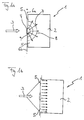
- FIG. 1 a shows a reactor system 1 for example for the autothermal reforming of a hydrocarbon or hydrocarbon derivative, such as methanol, in a starting operating phase, which has a reaction space 2.
- This contains a suitable catalyst material, not shown further. If the catalyst material is exposed to a mixture of air, water and hydrocarbon or hydrocarbon derivative as reaction reactants at a suitable temperature, an H 2 -rich gas is formed in the course of a catalytic reaction, which, if necessary after further processing, for the operation of a fuel cell, for example Fuel cell vehicle can be used.
- a certain minimum temperature above room temperature is required for an effective course of the catalytic reaction on the catalyst material.
- a reaction product mixture 3 is fed to the reaction space 2 via an electrical heating device 4 which is permeable to the liquid or gaseous mixture flow.
- the heating device 4 partially covers the entry cross section 5 for reaction reactants into the reaction space 2 in the form of a plate or disk. It is connected via electrical lines 6a, 6b to an electrical energy source, not shown, for example a motor vehicle battery.
- the heating device 4 has a relatively small mass and thus only a small heat capacity, so that it can be electrically heated to a desired operating temperature quickly with relatively little power.
- the heating device 4 is coated with catalyst material which, if the heating device 4 has reached its operating temperature, catalyzes an exothermic reaction of the reaction reactants flowing through it.
- a heated reaction product mixture which has already reacted somewhat is thus supplied to the reaction chamber 2 via the heating device.
- the high temperature of this reaction adduct mixture supplied to the reaction space is due on the one hand to the heat generated electrically in the heating device 4, but on the other hand energy is also released by the exothermic catalytic reaction.
- a temperature profile 8 forms in the reaction chamber 2, which the heating element 4 as a heat source at the reaction space inlet 9 underlying.
- Starting from the area of the heating element 4 at the reaction space inlet 9 thus becomes the one located in the reaction space 2 Catalyst material heated up quickly, so that the catalytic reaction that started in the heater 4 was continued quickly.
- heat is transferred through Solid-state heat conduction over the catalyst material and optionally via support structures in reaction chamber 2 as well the mass flow of reactants or product gases in the reaction space 2 transported.
- the one in the catalytic reaction The energy released leads to rapid heating of the entire reaction space.
- reaction 1b shows the reactor system 1 in a normal operating phase.
- the reaction space 2 In order to supply reaction mixture 3 to those in the reaction chamber 2 adaptable amount, if the reaction space 2 has reached an optimal operating temperature, the reaction reactants over the entire inlet cross section 5 of the reaction space 2 fed.
- the reactor system 1 During normal operation of the reactor system 1 is due to the exothermic or autothermal catalytic reaction released enough energy in reaction chamber 2, so that preheating of reactants by means of the heating device 4 is no longer required. The latter can therefore be switched off stay.
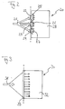
- FIG. 2 shows a reactor system 20, the mode of operation of which corresponds to that of the system of FIGS. 1a and 1b.
- the several inlet-side heating elements 22, 23, 24 comprises to a reaction educt stream 21 via reaction space inlets 25, 26 and 27 to feed a reaction chamber 28.
- These heating elements 22, 23, 24 become a starting operating phase supplied with electrical energy. They then cause them to enter the reaction space 25, 26 and 27 immediately the catalytic Combustion reaction of the reactants supplied, so that the entire reaction space 28 behind it quickly opens up heats up a desired operating temperature.
- reactor system allows this Reactor system 20 from FIG. 2 with a correspondingly greater heating power faster heating to operating temperature.
- FIG. 3 shows a further exemplary embodiment 30 for a reactor system.
- a reaction product stream 31 is fed into a reaction space 32 by a catalyst-covered, electrically heated Heating disc 33 supplied.
- Heating disc 32 with energy from a not shown electrical energy source heated to a temperature that a catalytic reaction of reactants passing through them triggers.
- Heating output an even shorter start-up phase can be achieved.
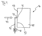
- a reactor system 40 in which in a Start operating phase of one of the reactants, namely air, by means of an electric heater 41 when flowing through one Supply line 42 is heated to in an entry area 43 of reaction reactants in a reaction space 45 with the Hydrocarbon or hydrocarbon derivative feed 44 to be mixed up.
- the resulting reactant mixture reaches it selectively, as shown on one Place or in a manner not shown alternatively at several Place at a reaction space inlet 46 in the reaction space 45. It has a temperature due to its proportion of heated air, which is the rapid start of a catalytic combustion reaction on the catalyst material in the area of the Air injection at the reaction space inlet 46 causes. Consequently forms, as shown in FIGS.
- Reactor systems in a start-up phase stoichiometric mixture of reactants, especially of Provide air and hydrocarbon or hydrocarbon derivative to be able to use one with battery energy if required operated air compressor.
- the described reactor systems are also temperature control about the respective heaters that they included, accessible. The temperature in the reaction chamber drops below a predetermined threshold, so be easy Reaction educts on the activated electrical concerned Heaters fed. In analogy to the operation of the reactor systems in a start-up phase this causes one rapid temperature rise. When the desired temperature is reached the heaters are turned off again.
- the Reactor system preferably includes a switchable reactant feed system, which contains controllable feed means.
- the start operating mode of the reactor system becomes a reaction reduct stream over part of the inlet cross-section of the reaction space fed.
- the reactant feed system is used for normal operation switched, and the reactant stream is over an entire inlet cross-section in the reaction space headed.
Landscapes
- Chemical & Material Sciences (AREA)
- Chemical Kinetics & Catalysis (AREA)
- Organic Chemistry (AREA)
- Health & Medical Sciences (AREA)
- General Health & Medical Sciences (AREA)
- Engineering & Computer Science (AREA)
- Combustion & Propulsion (AREA)
- Inorganic Chemistry (AREA)
- Hydrogen, Water And Hydrids (AREA)
- Physical Or Chemical Processes And Apparatus (AREA)
- Devices And Processes Conducted In The Presence Of Fluids And Solid Particles (AREA)
Abstract
Description
- Fig. 1a und 1b
- schematische Seitenansichten eines ersten Ausführungsbeispiels eines Reaktorsystems zur Umsetzung eines Kohlenwasserstoff- oder Kohlenwasserstoffderivat-Einsatzstoffes in einer Startbetriebsphase bzw. einer Normalbetriebsphase,
- Fig. 2, 3 und 4
- schematische Seitenansichten weiterer Ausführungsbeispiele von Reaktorsystemen.
Um beim Kaltstart den kalten, sich auf Umgebungstemperatur befindlichen Reaktionsraum 2 schnell auf die Betriebstemperatur zu bringen, wird ein Reaktionseduktgemisch 3 über eine für den flüssigen oder gasförmigen Gemischstrom durchlässige elektrische Heizvorrichtung 4 dem Reaktionsraum 2 zugeführt. Die Heizvorrichtung 4 deckt platten- bzw. scheibenförmig den Eintrittsquerschnitt 5 für Reaktionsedukte in den Reaktionsraum 2 teilweise ab. Über elektrische Leitungen 6a, 6b ist sie an eine nicht weiter dargestellte elektrische Energiequelle, beispielsweise eine Kraftfahrzeug-Batterie, angeschlossen. Die Heizvorrichtung 4 hat eine relativ geringe Masse und damit nur eine kleine Wärmekapazität, so daß sie schnell mit relativ geringer Leistung auf eine gewünschte Betriebstemperatur elektrisch aufgeheizt werden kann. Weiter ist die Heizvorrichtung 4 mit Katalysatormaterial belegt, das, sofern die Heizvorrichtung 4 ihre Betriebstemperatur erreicht hat, eine exotherme Reaktion der durch sie strömenden Reaktionsedukte katalysiert. Damit wird über die Heizvorrichtung dem Reaktionsraum 2 eine erhitzte Reaktionseduktmischung zugeführt, die schon etwas reagiert ist. Die hohe Temperatur dieser dem Reaktionsraum zugeführten Reaktionseduktmischung geht zum einen auf die in der Heizvorrichtung 4 elektrisch erzeugte Wärme zurück, zum andern wird jedoch auch durch die exotherme katalytische Reaktion Energie freigesetzt.
Claims (5)
- Reaktorsystem zur Umsetzung eines Kohlenwasserstoff- oder Kohlenwasserstoffderivat-Einsatzstoffs miteinem katalysatorbelegten Reaktionsraum, dem ein Reaktionseduktstrom über einen Reaktionsraumeintritt zuführbar ist, undelektrischen Heizmitteln, die von einer katalysatorbelegten und für den Reaktionseduktstrom (3, 21, 31) durchlässigen elektrischen Heizvorrichtung (4, 22, 23, 24, 33) gebildet sind, durch die hindurch wenigstens in einer Startbetriebsphase des Reaktorsystems (1, 20, 30) Edukte (3, 21, 31) für die Umsetzung des Einsatzstoffs zuführbar sind,
dadurch gekennzeichnet, daßdie elektrische Heizvorrichtung flächig ausgebildet und auf Höhe des Reaktionsraumeintritts (9, 25, 26, 27) dessen Eintrittsquerschnitt (5) wenigstens teilweise abdeckend angeordnet ist. - Reaktorsystem nach Anspruch 1,
dadurch gekennzeichnet, daß
die Heizvorrichtung mehrere Heizelemente (22, 23, 24) aufweist, die zusammen den Eintrittsquerschnitt des Reaktionsraumes (2) ganz oder teilweise abdecken. - Reaktorsystem nach Anspruch 1,
dadurch gekennzeichnet, daß
die Heizvorrichtung eine Heizscheibe (33) aufweist, die den Eintrittsquerschnitt des Reaktionsraumes (32) vollständig abdeckt. - Reaktorsystem zur Umsetzung eines Kohlenwasserstoff- oder Kohlenwasserstoffderivat-Einsatzstoffs miteinem katalysatorbelegten Reaktionsraum, dem ein Reaktionseduktstrom über einen Reaktionsraumeintritt zuführbar ist, undelektrischen Heizmitteln, die eine vor dem Reaktionsraumeintritt (46) befindliche elektrische Heizvorrichtung (41) zum Aufheizen wenigstens eines Reaktionseduktes in einer Startbetriebsphase beinhalten,
dadurch gekennzeichnet, daßdie elektrischen Heizmittel Mittel zum punktuellen Einbringen des wenigstens einen in der Heizvorrichtung (41) aufgeheizten Reaktionseduktes in den Reaktionsraum (45) an einer oder mehreren Stellen des Reaktionsraumeintrittsquerschnitts aufweisen. - Reaktorsystem nach einem der Ansprüche 1 bis 4,
dadurch gekennzeichnet, daß
das Reaktorsystem (1, 20, 30, 40) ein schaltbares Reaktionsedukt-Zufuhrsystem mit Zufuhrmitteln umfaßt, die den Reaktionseduktstrom (3, 21, 31, 44) in einem Startbetriebsmodus nur über einen Teil des Eintrittsquerschnittes (5, 47) in den Reaktionsraum (2, 28, 32, 45) und in einem Normalbetriebsmodus über den gesamten Eintrittsquerschnitt (5, 47) in den Reaktionsraum (2, 28, 32, 45) zuführen.
Priority Applications (1)
| Application Number | Priority Date | Filing Date | Title |
|---|---|---|---|
| EP04013377A EP1464616A2 (de) | 1999-09-17 | 2000-09-06 | Reaktorsystem mit elektrischen Heizmitteln |
Applications Claiming Priority (2)
| Application Number | Priority Date | Filing Date | Title |
|---|---|---|---|
| DE19944540 | 1999-09-17 | ||
| DE19944540A DE19944540B4 (de) | 1999-09-17 | 1999-09-17 | Reaktorsystem mit elektrischen Heizmitteln |
Related Child Applications (1)
| Application Number | Title | Priority Date | Filing Date |
|---|---|---|---|
| EP04013377A Division EP1464616A2 (de) | 1999-09-17 | 2000-09-06 | Reaktorsystem mit elektrischen Heizmitteln |
Publications (2)
| Publication Number | Publication Date |
|---|---|
| EP1084991A2 true EP1084991A2 (de) | 2001-03-21 |
| EP1084991A3 EP1084991A3 (de) | 2003-07-09 |
Family
ID=7922326
Family Applications (2)
| Application Number | Title | Priority Date | Filing Date |
|---|---|---|---|
| EP04013377A Withdrawn EP1464616A2 (de) | 1999-09-17 | 2000-09-06 | Reaktorsystem mit elektrischen Heizmitteln |
| EP00119232A Withdrawn EP1084991A3 (de) | 1999-09-17 | 2000-09-06 | Reaktorsystem mit elektrischen Heizmitteln |
Family Applications Before (1)
| Application Number | Title | Priority Date | Filing Date |
|---|---|---|---|
| EP04013377A Withdrawn EP1464616A2 (de) | 1999-09-17 | 2000-09-06 | Reaktorsystem mit elektrischen Heizmitteln |
Country Status (3)
| Country | Link |
|---|---|
| US (1) | US7025941B1 (de) |
| EP (2) | EP1464616A2 (de) |
| DE (1) | DE19944540B4 (de) |
Cited By (1)
| Publication number | Priority date | Publication date | Assignee | Title |
|---|---|---|---|---|
| DE102006019061B4 (de) | 2006-04-25 | 2018-11-29 | Eberspächer Climate Control Systems GmbH & Co. KG | Verdampferbaugruppe zur Erzeugung von Brennstoffdampf |
Families Citing this family (17)
| Publication number | Priority date | Publication date | Assignee | Title |
|---|---|---|---|---|
| DE10141776A1 (de) * | 2001-08-25 | 2003-03-06 | Ballard Power Systems | Verfahren zum Starten eines katalytischen Reaktors |
| DE10144891A1 (de) * | 2001-09-12 | 2003-03-27 | Basf Ag | Alternatives Reaktorkonzept zur Blausäureherstellung |
| DE10237744A1 (de) * | 2002-08-17 | 2004-03-04 | Daimlerchrysler Ag | Reaktorsystem zur Wasserstofferzeugung |
| DE10243275A1 (de) * | 2002-09-18 | 2004-04-01 | Volkswagen Ag | Reformereinrichtung für ein Brennstoffzellensystem und Verfahren zum Erzeugen von Wasserstoff durch Reformieren eines Betriebsmediums |
| CN111372675B (zh) * | 2017-11-25 | 2022-08-23 | 星火能源公司 | 具有集成的热交换器的化学反应器 |
| US11492255B2 (en) | 2020-04-03 | 2022-11-08 | Saudi Arabian Oil Company | Steam methane reforming with steam regeneration |
| US11322766B2 (en) | 2020-05-28 | 2022-05-03 | Saudi Arabian Oil Company | Direct hydrocarbon metal supported solid oxide fuel cell |
| US11639290B2 (en) | 2020-06-04 | 2023-05-02 | Saudi Arabian Oil Company | Dry reforming of methane with carbon dioxide at elevated pressure |
| US11492254B2 (en) | 2020-06-18 | 2022-11-08 | Saudi Arabian Oil Company | Hydrogen production with membrane reformer |
| US11999619B2 (en) | 2020-06-18 | 2024-06-04 | Saudi Arabian Oil Company | Hydrogen production with membrane reactor |
| US11583824B2 (en) | 2020-06-18 | 2023-02-21 | Saudi Arabian Oil Company | Hydrogen production with membrane reformer |
| US12220666B2 (en) | 2021-01-12 | 2025-02-11 | Saudi Arabian Oil Company | Ultrathin membrane fabrication |
| US12258272B2 (en) | 2021-08-12 | 2025-03-25 | Saudi Arabian Oil Company | Dry reforming of methane using a nickel-based bi-metallic catalyst |
| US11718575B2 (en) | 2021-08-12 | 2023-08-08 | Saudi Arabian Oil Company | Methanol production via dry reforming and methanol synthesis in a vessel |
| US11787759B2 (en) | 2021-08-12 | 2023-10-17 | Saudi Arabian Oil Company | Dimethyl ether production via dry reforming and dimethyl ether synthesis in a vessel |
| US11578016B1 (en) | 2021-08-12 | 2023-02-14 | Saudi Arabian Oil Company | Olefin production via dry reforming and olefin synthesis in a vessel |
| US11617981B1 (en) | 2022-01-03 | 2023-04-04 | Saudi Arabian Oil Company | Method for capturing CO2 with assisted vapor compression |
Family Cites Families (16)
| Publication number | Priority date | Publication date | Assignee | Title |
|---|---|---|---|---|
| US3982910A (en) * | 1974-07-10 | 1976-09-28 | The United States Of America As Represented By The Administrator Of The National Aeronautics And Space Administration | Hydrogen-rich gas generator |
| DE2542997C2 (de) * | 1975-09-26 | 1982-11-11 | Siemens AG, 1000 Berlin und 8000 München | Verfahren und Vorrichtung zum Starten eines Gasgenerators zur Umsetzung von Kohlenwasserstoffen in ein Brenngas und einer mit dem Brenngas zu speisenden Brennkraftmaschine |
| JPS58219975A (ja) | 1982-06-14 | 1983-12-21 | 株式会社東芝 | 自動取出装置付区分機 |
| US4473622A (en) * | 1982-12-27 | 1984-09-25 | Chludzinski Paul J | Rapid starting methanol reactor system |
| JPH03218902A (ja) * | 1990-01-23 | 1991-09-26 | Mitsubishi Heavy Ind Ltd | 水素原料改質装置の始動方法 |
| DE4035971A1 (de) * | 1990-11-12 | 1992-05-14 | Emitec Emissionstechnologie | Beheizbare katalysatoranordnung fuer die abgasreinigung von verbrennungsmotoren |
| US5366821A (en) * | 1992-03-13 | 1994-11-22 | Ballard Power Systems Inc. | Constant voltage fuel cell with improved reactant supply and control system |
| GB2268694A (en) * | 1992-07-14 | 1994-01-19 | Rolls Royce Plc | A catalytic combustion chamber |
| JP3403494B2 (ja) * | 1994-05-23 | 2003-05-06 | 日本碍子株式会社 | 改質反応器 |
| US5833723A (en) * | 1995-02-27 | 1998-11-10 | Aisin Seiki Kabushiki Kaisha | Hydrogen generating apparatus |
| DE19526886C1 (de) * | 1995-07-22 | 1996-09-12 | Daimler Benz Ag | Verfahren und Vorrichtung zur Methanolreformierung |
| DE19639150C2 (de) * | 1996-09-24 | 1998-07-02 | Daimler Benz Ag | Zentrale Heizvorrichtung für ein Gaserzeugungssystem |
| DE19727841A1 (de) * | 1997-06-24 | 1999-01-07 | Fraunhofer Ges Forschung | Verfahren und Vorrichtung zur autothermen Reformierung von Kohlenwasserstoffen |
| JPH11130405A (ja) * | 1997-10-28 | 1999-05-18 | Ngk Insulators Ltd | 改質反応装置、触媒装置、それらに用いる発熱・触媒体、及び改質反応装置の運転方法 |
| US6077620A (en) * | 1997-11-26 | 2000-06-20 | General Motors Corporation | Fuel cell system with combustor-heated reformer |
| JP2000007301A (ja) * | 1998-06-29 | 2000-01-11 | Ngk Insulators Ltd | 改質反応装置 |
-
1999
- 1999-09-17 DE DE19944540A patent/DE19944540B4/de not_active Expired - Fee Related
-
2000
- 2000-09-06 EP EP04013377A patent/EP1464616A2/de not_active Withdrawn
- 2000-09-06 EP EP00119232A patent/EP1084991A3/de not_active Withdrawn
- 2000-09-18 US US09/664,539 patent/US7025941B1/en not_active Expired - Fee Related
Cited By (1)
| Publication number | Priority date | Publication date | Assignee | Title |
|---|---|---|---|---|
| DE102006019061B4 (de) | 2006-04-25 | 2018-11-29 | Eberspächer Climate Control Systems GmbH & Co. KG | Verdampferbaugruppe zur Erzeugung von Brennstoffdampf |
Also Published As
| Publication number | Publication date |
|---|---|
| EP1084991A3 (de) | 2003-07-09 |
| DE19944540A1 (de) | 2001-03-29 |
| DE19944540B4 (de) | 2005-01-13 |
| EP1464616A2 (de) | 2004-10-06 |
| US7025941B1 (en) | 2006-04-11 |
Similar Documents
| Publication | Publication Date | Title |
|---|---|---|
| EP1084991A2 (de) | Reaktorsystem mit elektrischen Heizmitteln | |
| EP0831055B1 (de) | Zentrale Heizvorrichtung für ein Gaserzeugungssystem | |
| EP0924161B1 (de) | Verfahren zum Betrieb einer Wasserdampfreformierungsanlage, damit betreibbare Reformierungsanlage und Brennstoffzellensystembetriebsverfahren | |
| EP1394102B1 (de) | Verdampferanordnung, insbesondere zur Erzeugung eines in einem Reformer zur Wasserstoffgewinnung zersetzbaren Kohlenwasserstoff/Mischmaterial-Gemisches | |
| EP0924162A2 (de) | Wasserstoffabtrennmembran, damit ausgerüstete Methanolreformierungsanlage und Betriebsverfahren hierfür | |
| EP1553653B1 (de) | Brennstoffzellensystem | |
| DE19754013A1 (de) | Vorrichtung und Verfahren zur Wasserdampfreformierung eines Kohlenwasserstoffs | |
| DE10127199A1 (de) | Verfahren zum Betrieb eines Brennstoffprozessors, der Partialoxidation und Dampfreformierung kombiniert | |
| EP1040079A1 (de) | Verfahren zum betrieb einer anlage zur wasserdampfreformierung eines kohlenwasserstoffs | |
| DE19721439A1 (de) | Zusatzheizung für Kraftfahrzeuge mit Verbrennungsmotoren | |
| DE102008018152B4 (de) | Brennstoffzellensystem und zugehöriges Betriebsverfahren | |
| DE10244883B4 (de) | Heizsystem für ein Fahrzeug | |
| DE19602287A1 (de) | Katalysator für Verbrennungsmotoren | |
| DE19902926C2 (de) | Reaktoranlage und Betriebsverfahren hierfür | |
| DE19955929C2 (de) | Verfahren zur autothermen Reformierung eines Kohlenwasserstoffs | |
| DE10007766A1 (de) | Brenneranordnung | |
| EP3899369B1 (de) | Brennersystem, system mit einem solchen brennersystem und verfahren zur bereitstellung von wärmeenergie mittels eines solchen brennersystems | |
| EP1524239B1 (de) | Verdampferanordnung zur Erzeugung eines in einem Reformer zur Wasserstoffgewinnung zersetzbaren Kohlenwasserstoff/Luft- oder/und Wasserdampf-Gemisches und Verfahren zum Betreiben einer derartigen Verdampferanordnung | |
| DE10104607A1 (de) | Gaserzeugungssystem für ein Brennstoffzellensystem und Verfahren zum Betrieb eines Gaserzeugungssystems | |
| DE102008009063A1 (de) | Brennstoffzellensystem | |
| DE10213891B4 (de) | Vorrichtung zur Umformung eines kohlenwasserstoffhaltigen Stoffstroms | |
| DE19717067C2 (de) | Reformierungsreaktoranlage, insbesondere zur Wasserdampfreformierung von Methanol | |
| DE10101098A1 (de) | Verfahren zum Betrieb einer Reformeranlage zur Bereitstellung von wasserstoffangereichertem Gas sowie Reformeranlage | |
| DE102020102055B4 (de) | Brennkammerbaugruppe | |
| EP1739777B1 (de) | Brennstoffzellensystem für ein Fahrzeug |
Legal Events
| Date | Code | Title | Description |
|---|---|---|---|
| PUAI | Public reference made under article 153(3) epc to a published international application that has entered the european phase |
Free format text: ORIGINAL CODE: 0009012 |
|
| AK | Designated contracting states |
Kind code of ref document: A2 Designated state(s): AT BE CH CY DE DK ES FI FR GB GR IE IT LI LU MC NL PT SE |
|
| AX | Request for extension of the european patent |
Free format text: AL;LT;LV;MK;RO;SI |
|
| PUAL | Search report despatched |
Free format text: ORIGINAL CODE: 0009013 |
|
| AK | Designated contracting states |
Designated state(s): AT BE CH CY DE DK ES FI FR GB GR IE IT LI LU MC NL PT SE |
|
| AX | Request for extension of the european patent |
Extension state: AL LT LV MK RO SI |
|
| 17P | Request for examination filed |
Effective date: 20031009 |
|
| AKX | Designation fees paid |
Designated state(s): DE FR GB IT |
|
| 17Q | First examination report despatched |
Effective date: 20040317 |
|
| RAP1 | Party data changed (applicant data changed or rights of an application transferred) |
Owner name: DAIMLERCHRYSLER AG |
|
| RAP1 | Party data changed (applicant data changed or rights of an application transferred) |
Owner name: DAIMLER AG |
|
| GRAP | Despatch of communication of intention to grant a patent |
Free format text: ORIGINAL CODE: EPIDOSNIGR1 |
|
| STAA | Information on the status of an ep patent application or granted ep patent |
Free format text: STATUS: THE APPLICATION IS DEEMED TO BE WITHDRAWN |
|
| 18D | Application deemed to be withdrawn |
Effective date: 20091020 |