EP1087102A2 - Gasturbinenschaufel mit prallgekühlter Plattform - Google Patents
Gasturbinenschaufel mit prallgekühlter Plattform Download PDFInfo
- Publication number
- EP1087102A2 EP1087102A2 EP00305769A EP00305769A EP1087102A2 EP 1087102 A2 EP1087102 A2 EP 1087102A2 EP 00305769 A EP00305769 A EP 00305769A EP 00305769 A EP00305769 A EP 00305769A EP 1087102 A2 EP1087102 A2 EP 1087102A2
- Authority
- EP
- European Patent Office
- Prior art keywords
- platform
- bore
- root portion
- tube
- airfoil
- Prior art date
- Legal status (The legal status is an assumption and is not a legal conclusion. Google has not performed a legal analysis and makes no representation as to the accuracy of the status listed.)
- Granted
Links
Images
Classifications
-
- F—MECHANICAL ENGINEERING; LIGHTING; HEATING; WEAPONS; BLASTING
- F01—MACHINES OR ENGINES IN GENERAL; ENGINE PLANTS IN GENERAL; STEAM ENGINES
- F01D—NON-POSITIVE DISPLACEMENT MACHINES OR ENGINES, e.g. STEAM TURBINES
- F01D5/00—Blades; Blade-carrying members; Heating, heat-insulating, cooling or antivibration means on the blades or the members
- F01D5/12—Blades
- F01D5/14—Form or construction
- F01D5/18—Hollow blades, i.e. blades with cooling or heating channels or cavities; Heating, heat-insulating or cooling means on blades
- F01D5/187—Convection cooling
-
- F—MECHANICAL ENGINEERING; LIGHTING; HEATING; WEAPONS; BLASTING
- F02—COMBUSTION ENGINES; HOT-GAS OR COMBUSTION-PRODUCT ENGINE PLANTS
- F02C—GAS-TURBINE PLANTS; AIR INTAKES FOR JET-PROPULSION PLANTS; CONTROLLING FUEL SUPPLY IN AIR-BREATHING JET-PROPULSION PLANTS
- F02C7/00—Features, components parts, details or accessories, not provided for in, or of interest apart form groups F02C1/00 - F02C6/00; Air intakes for jet-propulsion plants
- F02C7/12—Cooling of plants
-
- F—MECHANICAL ENGINEERING; LIGHTING; HEATING; WEAPONS; BLASTING
- F01—MACHINES OR ENGINES IN GENERAL; ENGINE PLANTS IN GENERAL; STEAM ENGINES
- F01D—NON-POSITIVE DISPLACEMENT MACHINES OR ENGINES, e.g. STEAM TURBINES
- F01D25/00—Component parts, details, or accessories, not provided for in, or of interest apart from, other groups
- F01D25/08—Cooling; Heating; Heat-insulation
- F01D25/12—Cooling
-
- F—MECHANICAL ENGINEERING; LIGHTING; HEATING; WEAPONS; BLASTING
- F01—MACHINES OR ENGINES IN GENERAL; ENGINE PLANTS IN GENERAL; STEAM ENGINES
- F01D—NON-POSITIVE DISPLACEMENT MACHINES OR ENGINES, e.g. STEAM TURBINES
- F01D5/00—Blades; Blade-carrying members; Heating, heat-insulating, cooling or antivibration means on the blades or the members
- F01D5/02—Blade-carrying members, e.g. rotors
- F01D5/08—Heating, heat-insulating or cooling means
-
- F—MECHANICAL ENGINEERING; LIGHTING; HEATING; WEAPONS; BLASTING
- F05—INDEXING SCHEMES RELATING TO ENGINES OR PUMPS IN VARIOUS SUBCLASSES OF CLASSES F01-F04
- F05D—INDEXING SCHEME FOR ASPECTS RELATING TO NON-POSITIVE-DISPLACEMENT MACHINES OR ENGINES, GAS-TURBINES OR JET-PROPULSION PLANTS
- F05D2240/00—Components
- F05D2240/80—Platforms for stationary or moving blades
- F05D2240/81—Cooled platforms
-
- Y—GENERAL TAGGING OF NEW TECHNOLOGICAL DEVELOPMENTS; GENERAL TAGGING OF CROSS-SECTIONAL TECHNOLOGIES SPANNING OVER SEVERAL SECTIONS OF THE IPC; TECHNICAL SUBJECTS COVERED BY FORMER USPC CROSS-REFERENCE ART COLLECTIONS [XRACs] AND DIGESTS
- Y02—TECHNOLOGIES OR APPLICATIONS FOR MITIGATION OR ADAPTATION AGAINST CLIMATE CHANGE
- Y02T—CLIMATE CHANGE MITIGATION TECHNOLOGIES RELATED TO TRANSPORTATION
- Y02T50/00—Aeronautics or air transport
- Y02T50/60—Efficient propulsion technologies, e.g. for aircraft
Definitions
- This invention relates to the cooling of turbine buckets and, specifically, to the cooling of the platform region of the bucket, at the base of the airfoil.
- Stage one and stage two buckets in gas turbines experience high temperatures and stress, creating low cycle fatigue life concerns, particularly at the leading edge fillet where the airfoil joins the platform at the forward portion of the pressure side of the airfoil.
- the bucket platforms are cooled by air entering the cavity below the platform, but this arrangement is not completely satisfactory, particularly in connection with the leading edge fillet.
- This invention provides a unique solution to the above problem by directing cooling air through a tube, the forward end of which is located closely adjacent the underside of the platform, below the forward portion of the pressure side of the airfoil, so as to effectively impingement cool the platform in the localized region below the leading edge fillet.
- film cooling holes are formed in the platform itself so that air introduced into the cavity by the impingement cooling tube can escape the cavity and flow along the upper surface of the platform along the contour of the pressure side of the airfoil, in a direction toward the trailing edge of the airfoil.
- the invention in its broader aspects, relates to a turbine bucket having an airfoil portion and a root portion, with a substantially planar platform at an interface between the airfoil portion and root portion, a platform cooling arrangement comprising at least one bore in the root portion and at least one impingement cooling tube seated in the bore, the tube extending beyond the bore with an outlet in close proximity to a targeted area on an underside of the platform.
- the invention in another aspect, relates to a method of cooling a leading edge fillet region of a turbine bucket having an airfoil portion and a root portion, the airfoil portion joined to a platform extending over the root portion, comprising: a) providing a through bore in a leading side of a cover plate in the root portion, the bore communicating with a recess in the root portion underlying the airfoil portion; b) inserting a tube in the bore, with a tip of the tube extending beyond the bore and in close proximity to a targeted area on an underside of the platform; c) supplying cooling air to the recess via the tube such that the targeted area is impingement cooled by the cooling air passing through the tube.
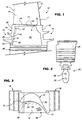
- a turbine bucket 10 includes an airfoil portion 12 extending vertically upwardly from a horizontal, substantially planar platform 14.
- the airfoil portion has a leading edge 15 and a trailing edge 17.
- the platform 14 is joined with the cover plate 24.
- Cooling passages extend in radially outward and inward directions in a serpentine path through the airfoil portion, the path having passages in the root portion communicating with supply and return passages 28, 30 in the dovetail.
- the internal airfoil cooling circuit forms no part of the invention, however, and is therefore not shown in detail.
- the substantially hollow space or recess 32 in the root portion above the dovetail 26 but below the platform 14, defined further by the sides 20, 22 of the cover plate.
- This recess is generally on the pressure side 34 of the airfoil, and it will be appreciated from Figure 3 that a relatively large portion of the platform 14 on the pressure side 34 of the airfoil overlies the hollow space or recess 32.
- An angled hole 36 is drilled through the leading side 20 of the cover plate 24 from the lower end of the root portion, on the external side thereof, extending upwardly (i.e., substantially radially) and opening into the recess 32. Due to the angled orientation, the hole 36 has an exit profile on the interior of the root wall 38 which is elliptical in shape as shown in Figure 2.
- An impingement cooling tube 40 is pressed into the hole 36 from under the root portion, so that an outlet at the upper end or tip 42 of the tube is located close to the underside of the platform, and close to a targeted area along the leading edge fillet 44 where the airfoil joins the platform.
- the lower end of the tube 40 is flared at 46 to limit the extent of insertion, and the tube may be fixed in place by a spot weld at 47 to prevent the tube from sliding back through the hole in a direction opposite the assembly direction.
- the tube end 42 is within about 0.5" from the underside of the platform.
- a second hole 48 is drilled from the leading side 20 of the cover plate 24 so as to intersect with the hole 36, just below the lower end of the tube 40. In this way, rotor or wheel space purge air can enter the tube 40 via hole 36.
- an array of film cooling holes 50 extend through the platform 14 from the recess 32 to a location on the external side of the platform.
- Another feature of the invention lies in the combination of the above described impingement cooling with film cooling along the upper surface of the platform. This is achieved by utilizing the array of film cooling holes 50 in the platform, allowing the cooling air in the hollow space 32 to exit along the top surface of the platform.
- the film cooling holes 50 are directionally oriented so that the cooling air merges with the gas path air and flows along the pressure side of the airfoil toward the trailing edge 17.
- the flowpath of the film cooling air is such that it can carry over to the suction side of the platform of the adjacent bucket, increasing the overall effectiveness of the system.
- the underside of the platform 14 can be provided with any suitable rough coat, thus increasing the surface area available for heat transfer.
- one or more additional impingement cooling tubes may be used in conjunction with the tube 40 to enhance heat transfer at targeted locations along the underside of the platform.
Landscapes
- Engineering & Computer Science (AREA)
- Mechanical Engineering (AREA)
- General Engineering & Computer Science (AREA)
- Chemical & Material Sciences (AREA)
- Combustion & Propulsion (AREA)
- Turbine Rotor Nozzle Sealing (AREA)
- Organic Low-Molecular-Weight Compounds And Preparation Thereof (AREA)
Applications Claiming Priority (2)
| Application Number | Priority Date | Filing Date | Title |
|---|---|---|---|
| US40458999A | 1999-09-24 | 1999-09-24 | |
| US404589 | 1999-09-24 |
Publications (3)
| Publication Number | Publication Date |
|---|---|
| EP1087102A2 true EP1087102A2 (de) | 2001-03-28 |
| EP1087102A3 EP1087102A3 (de) | 2004-01-02 |
| EP1087102B1 EP1087102B1 (de) | 2010-09-29 |
Family
ID=23600216
Family Applications (1)
| Application Number | Title | Priority Date | Filing Date |
|---|---|---|---|
| EP00305769A Expired - Lifetime EP1087102B1 (de) | 1999-09-24 | 2000-07-07 | Gasturbinenschaufel mit prallgekühlter Plattform |
Country Status (6)
| Country | Link |
|---|---|
| US (1) | US6431833B2 (de) |
| EP (1) | EP1087102B1 (de) |
| JP (1) | JP4571277B2 (de) |
| KR (1) | KR100592150B1 (de) |
| AT (1) | ATE483098T1 (de) |
| DE (1) | DE60045026D1 (de) |
Cited By (6)
| Publication number | Priority date | Publication date | Assignee | Title |
|---|---|---|---|---|
| WO2002050402A1 (en) * | 2000-12-19 | 2002-06-27 | General Electric Company | Impingement cooling scheme for platform of turbine bucket |
| US7309212B2 (en) | 2005-11-21 | 2007-12-18 | General Electric Company | Gas turbine bucket with cooled platform leading edge and method of cooling platform leading edge |
| US7416391B2 (en) | 2006-02-24 | 2008-08-26 | General Electric Company | Bucket platform cooling circuit and method |
| US7841828B2 (en) | 2006-10-05 | 2010-11-30 | Siemens Energy, Inc. | Turbine airfoil with submerged endwall cooling channel |
| EP1772592A3 (de) * | 2005-10-04 | 2010-12-08 | General Electric Company | Schmutzfeste Schaufel mit einer Plattform |
| EP3556996A1 (de) * | 2018-04-20 | 2019-10-23 | United Technologies Corporation | Schaufel mit einlassöffnung auf der vorderen stirnseite des fusses |
Families Citing this family (46)
| Publication number | Priority date | Publication date | Assignee | Title |
|---|---|---|---|---|
| US6805534B1 (en) | 2003-04-23 | 2004-10-19 | General Electric Company | Curved bucket aft shank walls for stress reduction |
| US6945749B2 (en) * | 2003-09-12 | 2005-09-20 | Siemens Westinghouse Power Corporation | Turbine blade platform cooling system |
| US7097417B2 (en) * | 2004-02-09 | 2006-08-29 | Siemens Westinghouse Power Corporation | Cooling system for an airfoil vane |
| US20050220618A1 (en) * | 2004-03-31 | 2005-10-06 | General Electric Company | Counter-bored film-cooling holes and related method |
| US7207775B2 (en) * | 2004-06-03 | 2007-04-24 | General Electric Company | Turbine bucket with optimized cooling circuit |
| US7189063B2 (en) * | 2004-09-02 | 2007-03-13 | General Electric Company | Methods and apparatus for cooling gas turbine engine rotor assemblies |
| US20060056968A1 (en) * | 2004-09-15 | 2006-03-16 | General Electric Company | Apparatus and methods for cooling turbine bucket platforms |
| US7186089B2 (en) * | 2004-11-04 | 2007-03-06 | Siemens Power Generation, Inc. | Cooling system for a platform of a turbine blade |
| US7708525B2 (en) * | 2005-02-17 | 2010-05-04 | United Technologies Corporation | Industrial gas turbine blade assembly |
| US7927073B2 (en) * | 2007-01-04 | 2011-04-19 | Siemens Energy, Inc. | Advanced cooling method for combustion turbine airfoil fillets |
| US8057178B2 (en) * | 2008-09-04 | 2011-11-15 | General Electric Company | Turbine bucket for a turbomachine and method of reducing bow wave effects at a turbine bucket |
| US8382436B2 (en) | 2009-01-06 | 2013-02-26 | General Electric Company | Non-integral turbine blade platforms and systems |
| US8147197B2 (en) * | 2009-03-10 | 2012-04-03 | Honeywell International, Inc. | Turbine blade platform |
| US8210813B2 (en) * | 2009-05-07 | 2012-07-03 | General Electric Company | Method and apparatus for turbine engines |
| US8133024B1 (en) | 2009-06-23 | 2012-03-13 | Florida Turbine Technologies, Inc. | Turbine blade with root corner cooling |
| US8523527B2 (en) * | 2010-03-10 | 2013-09-03 | General Electric Company | Apparatus for cooling a platform of a turbine component |
| US8444381B2 (en) * | 2010-03-26 | 2013-05-21 | General Electric Company | Gas turbine bucket with serpentine cooled platform and related method |
| US8647064B2 (en) | 2010-08-09 | 2014-02-11 | General Electric Company | Bucket assembly cooling apparatus and method for forming the bucket assembly |
| US9416666B2 (en) | 2010-09-09 | 2016-08-16 | General Electric Company | Turbine blade platform cooling systems |
| US8851846B2 (en) | 2010-09-30 | 2014-10-07 | General Electric Company | Apparatus and methods for cooling platform regions of turbine rotor blades |
| US8684664B2 (en) | 2010-09-30 | 2014-04-01 | General Electric Company | Apparatus and methods for cooling platform regions of turbine rotor blades |
| US8840369B2 (en) | 2010-09-30 | 2014-09-23 | General Electric Company | Apparatus and methods for cooling platform regions of turbine rotor blades |
| US8794921B2 (en) | 2010-09-30 | 2014-08-05 | General Electric Company | Apparatus and methods for cooling platform regions of turbine rotor blades |
| US8777568B2 (en) | 2010-09-30 | 2014-07-15 | General Electric Company | Apparatus and methods for cooling platform regions of turbine rotor blades |
| US8814517B2 (en) | 2010-09-30 | 2014-08-26 | General Electric Company | Apparatus and methods for cooling platform regions of turbine rotor blades |
| US8636470B2 (en) * | 2010-10-13 | 2014-01-28 | Honeywell International Inc. | Turbine blades and turbine rotor assemblies |
| US8814518B2 (en) | 2010-10-29 | 2014-08-26 | General Electric Company | Apparatus and methods for cooling platform regions of turbine rotor blades |
| US8636471B2 (en) | 2010-12-20 | 2014-01-28 | General Electric Company | Apparatus and methods for cooling platform regions of turbine rotor blades |
| US8753083B2 (en) | 2011-01-14 | 2014-06-17 | General Electric Company | Curved cooling passages for a turbine component |
| US8734111B2 (en) | 2011-06-27 | 2014-05-27 | General Electric Company | Platform cooling passages and methods for creating platform cooling passages in turbine rotor blades |
| US9366142B2 (en) | 2011-10-28 | 2016-06-14 | General Electric Company | Thermal plug for turbine bucket shank cavity and related method |
| US8893507B2 (en) | 2011-11-04 | 2014-11-25 | General Electric Company | Method for controlling gas turbine rotor temperature during periods of extended downtime |
| US8840370B2 (en) | 2011-11-04 | 2014-09-23 | General Electric Company | Bucket assembly for turbine system |
| US8870525B2 (en) | 2011-11-04 | 2014-10-28 | General Electric Company | Bucket assembly for turbine system |
| US8845289B2 (en) | 2011-11-04 | 2014-09-30 | General Electric Company | Bucket assembly for turbine system |
| US8858160B2 (en) | 2011-11-04 | 2014-10-14 | General Electric Company | Bucket assembly for turbine system |
| US9022735B2 (en) | 2011-11-08 | 2015-05-05 | General Electric Company | Turbomachine component and method of connecting cooling circuits of a turbomachine component |
| US9127560B2 (en) | 2011-12-01 | 2015-09-08 | General Electric Company | Cooled turbine blade and method for cooling a turbine blade |
| US9243503B2 (en) * | 2012-05-23 | 2016-01-26 | General Electric Company | Components with microchannel cooled platforms and fillets and methods of manufacture |
| US10180067B2 (en) | 2012-05-31 | 2019-01-15 | United Technologies Corporation | Mate face cooling holes for gas turbine engine component |
| US9121292B2 (en) | 2012-12-05 | 2015-09-01 | General Electric Company | Airfoil and a method for cooling an airfoil platform |
| EP2956627B1 (de) | 2013-02-15 | 2018-07-25 | United Technologies Corporation | Gasturbinenmotorkomponente mit kombinierter anpassungsfläche und plattformkühlung |
| US9810070B2 (en) | 2013-05-15 | 2017-11-07 | General Electric Company | Turbine rotor blade for a turbine section of a gas turbine |
| US9982542B2 (en) * | 2014-07-21 | 2018-05-29 | United Technologies Corporation | Airfoil platform impingement cooling holes |
| US11286809B2 (en) * | 2017-04-25 | 2022-03-29 | Raytheon Technologies Corporation | Airfoil platform cooling channels |
| US10968750B2 (en) | 2018-09-04 | 2021-04-06 | General Electric Company | Component for a turbine engine with a hollow pin |
Family Cites Families (27)
| Publication number | Priority date | Publication date | Assignee | Title |
|---|---|---|---|---|
| US2931623A (en) * | 1957-05-02 | 1960-04-05 | Orenda Engines Ltd | Gas turbine rotor assembly |
| DE1801475B2 (de) * | 1968-10-05 | 1971-08-12 | Daimler Benz Ag, 7000 Stuttgart | Luftgekuehlte turbinenschaufel |
| US3804551A (en) * | 1972-09-01 | 1974-04-16 | Gen Electric | System for the introduction of coolant into open-circuit cooled turbine buckets |
| US3834831A (en) * | 1973-01-23 | 1974-09-10 | Westinghouse Electric Corp | Blade shank cooling arrangement |
| US3936227A (en) | 1973-08-02 | 1976-02-03 | General Electric Company | Combined coolant feed and dovetailed bucket retainer ring |
| US3967353A (en) | 1974-07-18 | 1976-07-06 | General Electric Company | Gas turbine bucket-root sidewall piece seals |
| US4017213A (en) * | 1975-10-14 | 1977-04-12 | United Technologies Corporation | Turbomachinery vane or blade with cooled platforms |
| US4012167A (en) | 1975-10-14 | 1977-03-15 | United Technologies Corporation | Turbomachinery vane or blade with cooled platforms |
| US4244676A (en) | 1979-06-01 | 1981-01-13 | General Electric Company | Cooling system for a gas turbine using a cylindrical insert having V-shaped notch weirs |
| US4350473A (en) * | 1980-02-22 | 1982-09-21 | General Electric Company | Liquid cooled counter flow turbine bucket |
| US4531889A (en) | 1980-08-08 | 1985-07-30 | General Electric Co. | Cooling system utilizing flow resistance devices to distribute liquid coolant to air foil distribution channels |
| JPS63306204A (ja) * | 1987-06-08 | 1988-12-14 | Hitachi Ltd | インピンジメント冷却装置 |
| JP2862536B2 (ja) * | 1987-09-25 | 1999-03-03 | 株式会社東芝 | ガスタービンの翼 |
| US5344283A (en) * | 1993-01-21 | 1994-09-06 | United Technologies Corporation | Turbine vane having dedicated inner platform cooling |
| JP3110227B2 (ja) * | 1993-11-22 | 2000-11-20 | 株式会社東芝 | タービン冷却翼 |
| DE69505407T2 (de) * | 1994-08-24 | 1999-05-27 | Westinghouse Electric Corp., Pittsburgh, Pa. | Gasturbinenschaufel mit gekühlter plattform |
| JPH08240102A (ja) * | 1995-03-02 | 1996-09-17 | Mitsubishi Heavy Ind Ltd | ガスタービンの蒸気冷却翼 |
| US5536143A (en) * | 1995-03-31 | 1996-07-16 | General Electric Co. | Closed circuit steam cooled bucket |
| JPH0941903A (ja) * | 1995-07-27 | 1997-02-10 | Toshiba Corp | ガスタービン冷却動翼 |
| US5800124A (en) * | 1996-04-12 | 1998-09-01 | United Technologies Corporation | Cooled rotor assembly for a turbine engine |
| JP3426841B2 (ja) * | 1996-04-15 | 2003-07-14 | 三菱重工業株式会社 | ガスタービン動翼 |
| US5738489A (en) | 1997-01-03 | 1998-04-14 | General Electric Company | Cooled turbine blade platform |
| JP3500045B2 (ja) * | 1997-07-07 | 2004-02-23 | 三菱重工業株式会社 | ガスタービン動翼の蒸気冷却システム |
| JP3546135B2 (ja) * | 1998-02-23 | 2004-07-21 | 三菱重工業株式会社 | ガスタービン動翼のプラットフォーム |
| US6065931A (en) * | 1998-03-05 | 2000-05-23 | Mitsubishi Heavy Industries, Ltd. | Gas turbine moving blade |
| US6176678B1 (en) | 1998-11-06 | 2001-01-23 | General Electric Company | Apparatus and methods for turbine blade cooling |
| US6158962A (en) | 1999-04-30 | 2000-12-12 | General Electric Company | Turbine blade with ribbed platform |
-
2000
- 2000-07-07 AT AT00305769T patent/ATE483098T1/de not_active IP Right Cessation
- 2000-07-07 DE DE60045026T patent/DE60045026D1/de not_active Expired - Lifetime
- 2000-07-07 EP EP00305769A patent/EP1087102B1/de not_active Expired - Lifetime
- 2000-07-11 JP JP2000209173A patent/JP4571277B2/ja not_active Expired - Lifetime
- 2000-07-18 KR KR1020000040914A patent/KR100592150B1/ko not_active Expired - Fee Related
-
2001
- 2001-01-24 US US09/768,220 patent/US6431833B2/en not_active Expired - Lifetime
Cited By (6)
| Publication number | Priority date | Publication date | Assignee | Title |
|---|---|---|---|---|
| WO2002050402A1 (en) * | 2000-12-19 | 2002-06-27 | General Electric Company | Impingement cooling scheme for platform of turbine bucket |
| EP1772592A3 (de) * | 2005-10-04 | 2010-12-08 | General Electric Company | Schmutzfeste Schaufel mit einer Plattform |
| US7309212B2 (en) | 2005-11-21 | 2007-12-18 | General Electric Company | Gas turbine bucket with cooled platform leading edge and method of cooling platform leading edge |
| US7416391B2 (en) | 2006-02-24 | 2008-08-26 | General Electric Company | Bucket platform cooling circuit and method |
| US7841828B2 (en) | 2006-10-05 | 2010-11-30 | Siemens Energy, Inc. | Turbine airfoil with submerged endwall cooling channel |
| EP3556996A1 (de) * | 2018-04-20 | 2019-10-23 | United Technologies Corporation | Schaufel mit einlassöffnung auf der vorderen stirnseite des fusses |
Also Published As
| Publication number | Publication date |
|---|---|
| DE60045026D1 (de) | 2010-11-11 |
| ATE483098T1 (de) | 2010-10-15 |
| EP1087102A3 (de) | 2004-01-02 |
| EP1087102B1 (de) | 2010-09-29 |
| JP2001090501A (ja) | 2001-04-03 |
| US20010019696A1 (en) | 2001-09-06 |
| JP4571277B2 (ja) | 2010-10-27 |
| KR100592150B1 (ko) | 2006-06-23 |
| KR20010029956A (ko) | 2001-04-16 |
| US6431833B2 (en) | 2002-08-13 |
Similar Documents
| Publication | Publication Date | Title |
|---|---|---|
| EP1087102A2 (de) | Gasturbinenschaufel mit prallgekühlter Plattform | |
| US7309212B2 (en) | Gas turbine bucket with cooled platform leading edge and method of cooling platform leading edge | |
| JP4885200B2 (ja) | プラットフォームを有するガスタービン動翼およびその形成方法 | |
| CN102444430B (zh) | 用于涡轮转子叶片的平台冷却装置以及制备该平台冷却装置的方法 | |
| US7416391B2 (en) | Bucket platform cooling circuit and method | |
| US5927946A (en) | Turbine blade having recuperative trailing edge tip cooling | |
| KR101586210B1 (ko) | 가스 터빈용 모듈식 블레이드 또는 베인 및 그러한 블레이드 및 베인을 갖는 가스 터빈 | |
| US5915923A (en) | Gas turbine moving blade | |
| US20110223004A1 (en) | Apparatus for cooling a platform of a turbine component | |
| CN102444432B (zh) | 用于冷却涡轮转子叶片平台区的装置与方法 | |
| US20060056968A1 (en) | Apparatus and methods for cooling turbine bucket platforms | |
| KR20010077887A (ko) | 가스 터빈 버킷내의 폐쇄형 회로 스팀 냉각 구조체 및터빈 버킷 플랫폼의 냉각 방법 | |
| JP2014047786A (ja) | タービンローターブレードのプラットホーム領域のための冷却構成 | |
| KR20050078980A (ko) | 초소형 회로 플랫폼 | |
| EP0541207A1 (de) | Prallgekühltes Schaufelblatt mit einem die Blatthälften verbundendem Einsatz | |
| JP2000257401A (ja) | 冷却可能な翼形部 | |
| JP2005076636A (ja) | ガスタービンエンジンのロータ組立体を冷却するための方法及び装置 | |
| EP1734228B1 (de) | Deckelteil für eine Turbinenlaufschaufel | |
| CN110234840A (zh) | 用于燃气涡轮的涡轮动叶或涡轮静叶 | |
| US7645123B1 (en) | Turbine blade with TBC removed from blade tip region | |
| CZ20002548A3 (cs) | Lopatka turbíny se vzduchem chlazenou plošinou a způsob chlazení zaoblení náběžné hrany lopatky turbíny |
Legal Events
| Date | Code | Title | Description |
|---|---|---|---|
| PUAI | Public reference made under article 153(3) epc to a published international application that has entered the european phase |
Free format text: ORIGINAL CODE: 0009012 |
|
| AK | Designated contracting states |
Kind code of ref document: A2 Designated state(s): AT BE CH CY DE DK ES FI FR GB GR IE IT LI LU MC NL PT SE |
|
| AX | Request for extension of the european patent |
Free format text: AL;LT;LV;MK;RO;SI |
|
| PUAL | Search report despatched |
Free format text: ORIGINAL CODE: 0009013 |
|
| AK | Designated contracting states |
Kind code of ref document: A3 Designated state(s): AT BE CH CY DE DK ES FI FR GB GR IE IT LI LU MC NL PT SE |
|
| AX | Request for extension of the european patent |
Extension state: AL LT LV MK RO SI |
|
| 17P | Request for examination filed |
Effective date: 20040702 |
|
| AKX | Designation fees paid |
Designated state(s): AT BE CH CY DE DK ES FI FR GB GR IE IT LI LU MC NL PT SE |
|
| GRAP | Despatch of communication of intention to grant a patent |
Free format text: ORIGINAL CODE: EPIDOSNIGR1 |
|
| GRAJ | Information related to disapproval of communication of intention to grant by the applicant or resumption of examination proceedings by the epo deleted |
Free format text: ORIGINAL CODE: EPIDOSDIGR1 |
|
| GRAP | Despatch of communication of intention to grant a patent |
Free format text: ORIGINAL CODE: EPIDOSNIGR1 |
|
| GRAS | Grant fee paid |
Free format text: ORIGINAL CODE: EPIDOSNIGR3 |
|
| GRAA | (expected) grant |
Free format text: ORIGINAL CODE: 0009210 |
|
| AK | Designated contracting states |
Kind code of ref document: B1 Designated state(s): AT BE CH CY DE DK ES FI FR GB GR IE IT LI LU MC NL PT SE |
|
| REG | Reference to a national code |
Ref country code: GB Ref legal event code: FG4D |
|
| REG | Reference to a national code |
Ref country code: CH Ref legal event code: EP |
|
| REG | Reference to a national code |
Ref country code: CH Ref legal event code: NV Representative=s name: SERVOPATENT GMBH |
|
| REG | Reference to a national code |
Ref country code: IE Ref legal event code: FG4D |
|
| REF | Corresponds to: |
Ref document number: 60045026 Country of ref document: DE Date of ref document: 20101111 Kind code of ref document: P |
|
| PG25 | Lapsed in a contracting state [announced via postgrant information from national office to epo] |
Ref country code: FI Free format text: LAPSE BECAUSE OF FAILURE TO SUBMIT A TRANSLATION OF THE DESCRIPTION OR TO PAY THE FEE WITHIN THE PRESCRIBED TIME-LIMIT Effective date: 20100929 Ref country code: AT Free format text: LAPSE BECAUSE OF FAILURE TO SUBMIT A TRANSLATION OF THE DESCRIPTION OR TO PAY THE FEE WITHIN THE PRESCRIBED TIME-LIMIT Effective date: 20100929 |
|
| REG | Reference to a national code |
Ref country code: NL Ref legal event code: VDEP Effective date: 20100929 |
|
| PG25 | Lapsed in a contracting state [announced via postgrant information from national office to epo] |
Ref country code: GR Free format text: LAPSE BECAUSE OF FAILURE TO SUBMIT A TRANSLATION OF THE DESCRIPTION OR TO PAY THE FEE WITHIN THE PRESCRIBED TIME-LIMIT Effective date: 20101230 Ref country code: SE Free format text: LAPSE BECAUSE OF FAILURE TO SUBMIT A TRANSLATION OF THE DESCRIPTION OR TO PAY THE FEE WITHIN THE PRESCRIBED TIME-LIMIT Effective date: 20100929 |
|
| PG25 | Lapsed in a contracting state [announced via postgrant information from national office to epo] |
Ref country code: NL Free format text: LAPSE BECAUSE OF FAILURE TO SUBMIT A TRANSLATION OF THE DESCRIPTION OR TO PAY THE FEE WITHIN THE PRESCRIBED TIME-LIMIT Effective date: 20100929 Ref country code: PT Free format text: LAPSE BECAUSE OF FAILURE TO SUBMIT A TRANSLATION OF THE DESCRIPTION OR TO PAY THE FEE WITHIN THE PRESCRIBED TIME-LIMIT Effective date: 20110131 Ref country code: IT Free format text: LAPSE BECAUSE OF FAILURE TO SUBMIT A TRANSLATION OF THE DESCRIPTION OR TO PAY THE FEE WITHIN THE PRESCRIBED TIME-LIMIT Effective date: 20100929 |
|
| PG25 | Lapsed in a contracting state [announced via postgrant information from national office to epo] |
Ref country code: BE Free format text: LAPSE BECAUSE OF FAILURE TO SUBMIT A TRANSLATION OF THE DESCRIPTION OR TO PAY THE FEE WITHIN THE PRESCRIBED TIME-LIMIT Effective date: 20100929 |
|
| PG25 | Lapsed in a contracting state [announced via postgrant information from national office to epo] |
Ref country code: ES Free format text: LAPSE BECAUSE OF FAILURE TO SUBMIT A TRANSLATION OF THE DESCRIPTION OR TO PAY THE FEE WITHIN THE PRESCRIBED TIME-LIMIT Effective date: 20110109 |
|
| PLBE | No opposition filed within time limit |
Free format text: ORIGINAL CODE: 0009261 |
|
| STAA | Information on the status of an ep patent application or granted ep patent |
Free format text: STATUS: NO OPPOSITION FILED WITHIN TIME LIMIT |
|
| PG25 | Lapsed in a contracting state [announced via postgrant information from national office to epo] |
Ref country code: DK Free format text: LAPSE BECAUSE OF FAILURE TO SUBMIT A TRANSLATION OF THE DESCRIPTION OR TO PAY THE FEE WITHIN THE PRESCRIBED TIME-LIMIT Effective date: 20100929 |
|
| 26N | No opposition filed |
Effective date: 20110630 |
|
| REG | Reference to a national code |
Ref country code: DE Ref legal event code: R097 Ref document number: 60045026 Country of ref document: DE Effective date: 20110630 |
|
| PG25 | Lapsed in a contracting state [announced via postgrant information from national office to epo] |
Ref country code: MC Free format text: LAPSE BECAUSE OF NON-PAYMENT OF DUE FEES Effective date: 20110731 |
|
| REG | Reference to a national code |
Ref country code: IE Ref legal event code: MM4A |
|
| PG25 | Lapsed in a contracting state [announced via postgrant information from national office to epo] |
Ref country code: IE Free format text: LAPSE BECAUSE OF NON-PAYMENT OF DUE FEES Effective date: 20110707 |
|
| PG25 | Lapsed in a contracting state [announced via postgrant information from national office to epo] |
Ref country code: LU Free format text: LAPSE BECAUSE OF NON-PAYMENT OF DUE FEES Effective date: 20110707 Ref country code: CY Free format text: LAPSE BECAUSE OF EXPIRATION OF PROTECTION Effective date: 20100929 |
|
| PGFP | Annual fee paid to national office [announced via postgrant information from national office to epo] |
Ref country code: FR Payment date: 20130717 Year of fee payment: 14 Ref country code: GB Payment date: 20130729 Year of fee payment: 14 |
|
| GBPC | Gb: european patent ceased through non-payment of renewal fee |
Effective date: 20140707 |
|
| REG | Reference to a national code |
Ref country code: FR Ref legal event code: ST Effective date: 20150331 |
|
| PG25 | Lapsed in a contracting state [announced via postgrant information from national office to epo] |
Ref country code: GB Free format text: LAPSE BECAUSE OF NON-PAYMENT OF DUE FEES Effective date: 20140707 Ref country code: FR Free format text: LAPSE BECAUSE OF NON-PAYMENT OF DUE FEES Effective date: 20140731 |
|
| PGFP | Annual fee paid to national office [announced via postgrant information from national office to epo] |
Ref country code: CH Payment date: 20190624 Year of fee payment: 20 |
|
| PGFP | Annual fee paid to national office [announced via postgrant information from national office to epo] |
Ref country code: DE Payment date: 20190620 Year of fee payment: 20 |
|
| REG | Reference to a national code |
Ref country code: CH Ref legal event code: PCAR Free format text: NEW ADDRESS: WANNERSTRASSE 9/1, 8045 ZUERICH (CH) |
|
| REG | Reference to a national code |
Ref country code: DE Ref legal event code: R071 Ref document number: 60045026 Country of ref document: DE |
|
| REG | Reference to a national code |
Ref country code: CH Ref legal event code: PL |