EP1087236A2 - Verfahren und System zur Inspektion einer fahrzeugmontierte n Kamera - Google Patents
Verfahren und System zur Inspektion einer fahrzeugmontierte n Kamera Download PDFInfo
- Publication number
- EP1087236A2 EP1087236A2 EP00120177A EP00120177A EP1087236A2 EP 1087236 A2 EP1087236 A2 EP 1087236A2 EP 00120177 A EP00120177 A EP 00120177A EP 00120177 A EP00120177 A EP 00120177A EP 1087236 A2 EP1087236 A2 EP 1087236A2
- Authority
- EP
- European Patent Office
- Prior art keywords
- vehicle
- camera
- inspection
- inspecting
- optical axis
- Prior art date
- Legal status (The legal status is an assumption and is not a legal conclusion. Google has not performed a legal analysis and makes no representation as to the accuracy of the status listed.)
- Withdrawn
Links
Images







Classifications
-
- G—PHYSICS
- G01—MEASURING; TESTING
- G01S—RADIO DIRECTION-FINDING; RADIO NAVIGATION; DETERMINING DISTANCE OR VELOCITY BY USE OF RADIO WAVES; LOCATING OR PRESENCE-DETECTING BY USE OF THE REFLECTION OR RERADIATION OF RADIO WAVES; ANALOGOUS ARRANGEMENTS USING OTHER WAVES
- G01S11/00—Systems for determining distance or velocity not using reflection or reradiation
- G01S11/12—Systems for determining distance or velocity not using reflection or reradiation using electromagnetic waves other than radio waves
-
- B—PERFORMING OPERATIONS; TRANSPORTING
- B60—VEHICLES IN GENERAL
- B60R—VEHICLES, VEHICLE FITTINGS, OR VEHICLE PARTS, NOT OTHERWISE PROVIDED FOR
- B60R11/00—Arrangements for holding or mounting articles, not otherwise provided for
- B60R11/04—Mounting of cameras operative during drive; Arrangement of controls thereof relative to the vehicle
-
- G—PHYSICS
- G01—MEASURING; TESTING
- G01B—MEASURING LENGTH, THICKNESS OR SIMILAR LINEAR DIMENSIONS; MEASURING ANGLES; MEASURING AREAS; MEASURING IRREGULARITIES OF SURFACES OR CONTOURS
- G01B11/00—Measuring arrangements characterised by the use of optical techniques
- G01B11/26—Measuring arrangements characterised by the use of optical techniques for measuring angles or tapers; for testing the alignment of axes
- G01B11/27—Measuring arrangements characterised by the use of optical techniques for measuring angles or tapers; for testing the alignment of axes for testing the alignment of axes
- G01B11/272—Measuring arrangements characterised by the use of optical techniques for measuring angles or tapers; for testing the alignment of axes for testing the alignment of axes using photoelectric detection means
-
- G—PHYSICS
- G01—MEASURING; TESTING
- G01S—RADIO DIRECTION-FINDING; RADIO NAVIGATION; DETERMINING DISTANCE OR VELOCITY BY USE OF RADIO WAVES; LOCATING OR PRESENCE-DETECTING BY USE OF THE REFLECTION OR RERADIATION OF RADIO WAVES; ANALOGOUS ARRANGEMENTS USING OTHER WAVES
- G01S11/00—Systems for determining distance or velocity not using reflection or reradiation
-
- H—ELECTRICITY
- H04—ELECTRIC COMMUNICATION TECHNIQUE
- H04N—PICTORIAL COMMUNICATION, e.g. TELEVISION
- H04N13/00—Stereoscopic video systems; Multi-view video systems; Details thereof
- H04N13/20—Image signal generators
- H04N13/204—Image signal generators using stereoscopic image cameras
- H04N13/239—Image signal generators using stereoscopic image cameras using two two-dimensional [2D] image sensors having a relative position equal to or related to the interocular distance
-
- H—ELECTRICITY
- H04—ELECTRIC COMMUNICATION TECHNIQUE
- H04N—PICTORIAL COMMUNICATION, e.g. TELEVISION
- H04N13/00—Stereoscopic video systems; Multi-view video systems; Details thereof
- H04N13/20—Image signal generators
- H04N13/204—Image signal generators using stereoscopic image cameras
- H04N13/25—Image signal generators using stereoscopic image cameras using two or more image sensors with different characteristics other than in their location or field of view, e.g. having different resolutions or colour pickup characteristics; using image signals from one sensor to control the characteristics of another sensor
-
- H—ELECTRICITY
- H04—ELECTRIC COMMUNICATION TECHNIQUE
- H04N—PICTORIAL COMMUNICATION, e.g. TELEVISION
- H04N13/00—Stereoscopic video systems; Multi-view video systems; Details thereof
- H04N2013/0074—Stereoscopic image analysis
- H04N2013/0081—Depth or disparity estimation from stereoscopic image signals
Definitions
- the invention relates to a method for inspecting cameras mounted on vehicles such as an automobile, and systems for the same.
- the stereo camera as the preview sensor, pinpoint accuracy is needed for an installation position of the stereo camera to the vehicle as well as the quality of the stereo camera itself.
- the displacing of the installation position of the camera causes a shift of the imaging direction, resulting in deterioration in the reliability of the monitor control.
- a distance is computed from parallax produced between a pair of imaged frames
- the shift of the imaging direction directly exerts an influence upon the computed distance.
- the angle of individual vehicle-mounted camera is varied due to the limitations associated with deformation of the car body itself or the accuracy of installing the camera.
- the image frames undergo an image transformation process, such as the affine transformation, to be finely adjusted with equivalence.
- the present invention has been made in consideration of the aforementioned circumstances. It is therefore an object of the present invention to provide a method and a system for efficiently inspecting a vehicle-mounted camera, with eliminating the need for using a conventional inspection apparatus and with employing cooperation of an image processing unit and a vehicle-mounted navigation control unit to determine the camera quality through the inspections of an optical axis direction, a distance measurement accuracy and so on, i.e. whether or not they are in correct ranges, and then to display the determined results on a monitor of the vehicle-mounted navigation control unit for recommending adjustment.
- a method for inspecting a vehicle-mounted camera is used for a vehicle monitoring system for imaging the view ahead of a vehicle with the camera installed to a vehicle body to recognize a running condition with an image processing unit, and includes the steps of inspecting the camera with the image processing unit to determine whether or not the camera quality is appropriate and displaying the inspected result on a monitor of a vehicle-mounted navigation control unit.
- the inspecting step for the quality assurance of the camera includes the steps of imaging an inspection chart, described with a reference pattern and placed at a predetermined position ahead of the vehicle, with the camera installed to the vehicle body, identifying a reference pattern on the camera image, and determining pass/fail of an optical axis direction of the camera on the basis of the relationship between a position of the identified reference pattern and a predetermined correct range defined for an imaging direction of the camera.
- the vehicle-mounted camera is attached through a replaceable attachment member to the vehicle body and has the imaging direction defined by a shape of the attachment member.
- another attachment member having a shape, optical axis direction by which is included in the correct range in the reference pattern of the recognized image is selected from a plurality of pre-prepared attachment members of varying shapes. Replacement of the attachment member with the selected attachment member is recommended.
- the inspecting step for the quality assurance of the camera includes the steps of imaging a plate described with a specific pattern and placed at a predetermined position ahead of the vehicle with the camera installed to the vehicle body, to calculate a distance image until the plate ahead of the vehicle with the image processing unit, and determining pass/fail of a distance measurement accuracy of the camera on a basis of comparison between the calculated distance image and a predetermined correct distance image characteristic.
- the present invention is for performing the inspection of at least the optical axis direction and the distance measurement accuracy for quality assurance of the vehicle-mounted camera to determine whether the camera quality is appropriate or not, and displaying the results on the monitor of the vehicle-mounted navigation control unit. For this reason, since the inspections for quality assurance relating to the visual check, the optical axis direction, the distance measurement accuracy and so on for the vehicle-mounted camera can be performed using the monitor of the vehicle-mounted navigation control unit, it is possible to eliminate the need for using any extra apparatus for the inspection processes, and also to reduce a working space for smoothly performing the inspections, resulting in significant efficiency of the inspection processes. Moreover, when the shifting of the imaging direction of the inspected camera is recognized, the information of the degree of shifting including the selection information for the replacement adjuster is provided to the operator for adjustment, resulting in efficiency of the re-adjusting process.
- a system for inspecting a vehicle-mounted camera is used for a vehicle monitoring system for imaging the view ahead of a vehicle with a camera installed to the vehicle body to recognize a running condition with an image processing unit, and includes inspection means provided in the image processing unit for quality assurance of the camera and for determining whether the camera quality is appropriate or not, and display means of a vehicle-mounted navigation control unit for displaying the determined result.
- the image processing unit includes a recognition main unit and a quality inspection section as the inspection means, and the quality inspection section designates at least one of an optical axis direction and a distance measurement accuracy as inspection items to determine pass/fail of the designated measurement, and assigns information of selecting a displayed screen defined for each inspection item into a communication data so as to transmit it to the navigation control unit.
- the system for inspecting the vehicle-mounted camera further includes switch means for starting the inspection means to execute the inspection for the quality assurance of the camera, and instructing the switching of a displayed screen defined for each inspection item.
- the monitor for the vehicle-mounted navigation unit can be used to inspect for quality assurance relating to the visual check, the optical axis direction, the distance measurement accuracy and so on for the vehicle-mounted camera, any extra apparatus is not needed for the inspection processes but the inspection is smoothly performed in the reduced working space. This allows the significant efficiency of the inspection processes.
- Fig. 1 is a block diagram illustrating an embodiment according to the present invention.
- a stereo camera is used as an example of the vehicle-mounted camera.
- the stereo camera 1 for imaging running conditions ahead of a vehicle has a camera 2a as a main camera and a camera 2b as a sub camera in pair which are disposed having a predetermined base line length.
- the installation of the stereo camera 1 to a car body is linked up with an inspecting method of the camera, so that it will be first explained in brief with reference to Figs. 11 to 14.
- Fig. 11 is a front view of the stereo camera 1
- Fig. 12 is an exploded view of the entire installation structure of the stereo camera 1
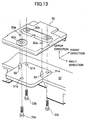
- Fig. 13 is an exploded view of a main part of an installing portion of the stereo camera 1
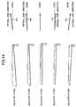
- Fig. 14 show varieties of an attachment member (adjuster) which is independent of the stereo camera assembly.
- a chassis 31 of the stereo camera 1 is made of an aluminum alloy having high stiffness not to be deformed by the weight of cameras 2a, 2b or changes in speed of the running vehicle.
- the main camera 2a is installed at the right end of the chassis 31 facing the forward direction of the vehicle.
- the camera 2a incorporates an image sensor such as CCD, and a reference image is produced under an output signal from the image sensor.
- the sub camera 2b is installed at the left end of the chassis 31, and an output signal from the camera 2b is used for producing a comparison image.
- three installing holes (for bolts 33) are formed to pass between the upper face and the lower face of the chassis 31.
- two locator pin 32 are formed for positioning the stereo camera 1 when being installed to the car body (a front rail 41).
- the stereo camera 1 i.e., the stereo camera assembly 1 including the cameras 2a, 2b
- the stereo camera 1 is mounted around a rearview mirror 40 on the car body (the front rail 41 in the embodiment) using an adjuster 30 as an attachment member.
- the adjuster 30 having a predetermined plate-thickness is interposed between the stereo camera assembly 1 and the front rail 41.
- the locator pins 32 formed on the chassis 31 are first inserted in respective positioning through-holes 30a formed on the adjuster 30. In this state, the position of the three installing holes 31a formed on the chassis 31 are respectively aligned with the three installing holes 30b formed on the adjuster 30.
- the locator pins 32 are respectively inserted in holes formed on the front rail 41. While in this state, subsequently, the three bolts 33a, 33b and 33c are respectively inserted in the three aligned through-holes 31a and 30b, to secure the stereo camera 1 onto the front rail 41. Then, after a switch connector 34 is connected to the stereo camera assembly 1, an outer cover 35 is fastened to the front rail 41 with bolts. And then, escutcheon plates 36 are respectively fitted into parts of the outer cover 35 where the bolts have been inserted, to make the appearance neat, and a sequence of installation operation is completed.
- the aforementioned attachment adjuster 30 is a member separated from the stereo camera assembly 1 or the chassis 31. Therefore, the adjuster 30 can be handled independently whenever being detached from the stereo camera assembly 1.
- the stereo camera assembly 1 is installed to the front rail 41 with the adjuster 30 in between.
- Using the independent attachment member from the camera body in the installation allows the attachment member to be replaced to make rough adjustment for the imaging direction of the stereo camera 1.
- This point is significantly distinct from the conventional approaches in which a stay integrated with a camera assembly is directly installed to a car body.
- a sectional form of the adjuster 30 in the longitudinal direction of the vehicle is designed to define vertical components of the imaging direction of the stereo camera 1, i.e. the optical axis L and R of the camera illustrated in Fig. 12.
- the imaging direction of the stereo camera 1 will adjust downward, or toward the ground, in proportion to the increased thickness.
- the plate-thickness of the adjuster 30 gradually increased from the front portion toward the rear portion, as illustrated with adjuster A in Fig. 14, the thicker the plate-thickness of the rear portion, the more upward the stereo camera 1 is oriented.
- the adjuster 30 can be removed from the stereo camera assembly 1 and handled independently.
- the imaging direction of the stereo camera 1 is therefore adjusted by replacing a current adjuster 30 with another adjuster 30 having a different form as required.
- a standard adjuster 30 having a certain form is commonly used to install the stereo camera assembly 1 to the car body.
- the standard adjuster 30 is replaced with a replacement adjuster.
- Various replacement adjusters are available as illustrated in Fig. 14, each of which is slightly different in form from one another (e.g. the degree and a direction of increasing the thickness).
- an adjuster having a proper form is used to adjust the variations of the imaging direction, resulting from accuracy in mechanical processes or deformation of the car body and the like, to within the correct range.
- An image signal outputted from the stereo camera 1 thus installed to the car body is processed by blocks positioned at the back as follows, while the cameras 2a and 2b are in synchronization with each other, the image signals outputted from the cameras 2a and 2b are applied to an image processing unit (hereinafter call IPU) 20.
- the IPU 20 is composed of a recognition main unit 21 and a quality inspection section 22.
- the recognition main unit 21 is provided for converting the image signal applied from the stereo camera 1 into a digital signal and for processing the image based on the signal.
- the quality inspection section 22 receives a startup request from an inspection switch 6 as described later, and then performs the inspection in cooperation with the recognition main unit 21, following the procedure shown in the flow charts of Figs. 2 and 3.
- a pre-view control unit (hereinafter call PCU) 4 serves as a control pivot of a vehicle monitoring system, which is connected to the IPU 20 through a communication cable (IPU-PCU communication path) 101.
- the PCU 4 and the IPU 20 exchange data with each other through the communication cable 101 in serial, to perform a variety of controls for monitoring the vehicle.
- a navigation control unit (hereinafter call NCU) 5 is composed of a navigation main unit 51 and a monitor 52 such as a liquid crystal display, and is connected to the IPU 20 through a video line 102 and to the PCU 4 through a communication cable (NCU-PCU communication path) 103.
- the inspection switch 6 is a simple switch used by an operator only when the quality of the camera is inspected. Upon connection of a connector of the IPU 20 by the operator, inspection mode is automatically set (GND state), and the quality inspection section 22 of the IPU 20 starts a software inspection routine. ON or OFF of an execution button 61 incorporated in the inspection switch 6 is set to maintain the GND state or an OPEN state, and to instruct the switching of the screen on the monitor 52 included in the NCU 5, and the like.
- Fig. 2 to Fig. 10 are illustrations for explaining operations in the embodiment of the present invention.
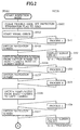
- Figs. 2 and 3 are flow charts for illustrating the procedure for inspecting the camera by the IPU 20 and the NCU 5.
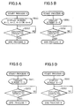
- Figs. 4 and 5 are flow charts for illustrating the operation procedures of the NCU 5 in the procedures of Figs. 2 and 3.
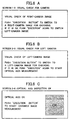
- Figs. 6, 7 and 8 are diagrams illustrating screen layouts displayed on the monitor 52 of the NCU 5.
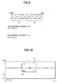
- Fig. 9 illustrates a format of data propagating along the communication cable 101
- Fig. 10 illustrates a pattern of brightness characteristics and a search range of the reference image provided for the adjustment of an optical axis.
- an operator connects the inspection switch 6 with a connector of the IPU 20 to start of the execution of inspection mode.
- the quality inspection section 22 of the IPU 20 sets a trouble code memory, assigned to a built-in memory, and an inspection terminating flag to " zero" to initialize the system (step S201 in Fig. 2).
- the trouble code is each code defined for a visual check, an optical axis direction and a distance measurement accuracy which will be hereinafter explained as quality inspection items.
- the item determined as quality deficiencies is code-set as condition information. Later, the operator will check the contents of the condition information on the monitor 52 of the NCU 5 for re-adjustment.
- the visual check is first selected as the inspection item (step S202 in Fig. 2).
- the monitor 52 of the NCU 5 displays a visual check screen (screen 1-0) for the right camera as illustrated in Fig. 6A (step S511 in Fig. 4A).
- the visual check screen is a guide screen for showing instructions for the following process.
- the operator pushes the execution button 61 to switch from the visual check screen for the right camera to an image screen of the right camera. If the operator sees nothing wrong on the image of the right camera, he/she must push the execution button 61 again to switch from the image screen to a visual check screen for the left camera.
- the navigation main unit 51 of NCU 5 monitors specified byte data (e.g., the most significant bit of the second byte of ID "51C") of a data packet propagating through the communication cable 103, the PCU 4 and the communication cable 101.
- the navigation main unit 51 refers to the bit to determine whether the execution button 61 is in ON or OFF.
- the navigation main unit 51 acknowledges the termination of the guide screen to the quality inspection section 22 of the IPU 20.
- the quality inspection section 22 provides to the NCU 5 an instruction for switching a screen to the navigation screen (step S203 in Fig. 2). This allows the NCU 5 to display a screen of "Processing" (screen 9-0) as shown in Fig. 8C on the monitor 52 through navigation main unit 51.
- the ON/OFF of the execution button 61 is assigned to the most significant bit of the aforementioned specified byte, and the ON/OFF state is reflected as information on the bit.
- the displaying of the navigation screen is defined using a specified byte (e.g., the fifth byte of ID "516") of a data packet propagating along the communication cable 101, and determined by a combination of the first half A and the latter half B of the specified byte.
- a specified byte e.g., the fifth byte of ID "516”
- the first half A is 2 and the latter half B is 0.
- the displayed navigation screen is screen 4-3 shown in Fig. 7C
- the first half A is 4 and the latter half B is 3.
- the quality inspection section 22 of the IPU 20 provides to the NCU 5 an instruction for switching from the aforementioned caption screen ("Processing") to the navigation screen for outputting the monitor image of the right camera (step S204 in Fig. 2).
- the NCU 5 receives the instruction and switches from the caption of the navigation screen displayed on the monitor 52 through the navigation main unit 51, to the monitor image of the right camera captured through the video line 102 (step S521 in Fig. 4B).
- the operator previews the camera image on the monitor 52 for the visual check, and if it is normal, he/she turns the execution button 61 ON to instruct the termination of the monitor visual check for the right camera.
- the navigation main unit 51 of the NCU 5 monitors ON of the execution button 61 and verifies the ON state (step S522 in Fig. 4B). After that, the navigation main unit 51 acknowledges the termination of the visual check for the right camera on the monitor to the quality inspection section 22 of the IPU 20 via the PCU 4 and the communication cable 101.
- the quality inspection section 22 of the IPU 20 which has received the acknowledgement provides an instruction for switching of the navigation screen to the NCU 5 (step S205 in Fig. 2).
- the NCU 5 uses the navigation main unit 51 to display a visual check instruction screen (screen 2-0) for the left camera illustrated in Fig. 6B on the monitor 52 (step S531 in Fig. 4C).
- This screen is for instructing as follows: the operator pushes the execution button 61 to switch to an image screen of the left camera. If the operator sees nothing wrong on the image of the left camera, he/she must push the execution button 61 again to switch from the image screen to a screen for the optical axis direction as the next inspection item.
- the navigation main unit 51 of the NCU 5 monitors specified byte data (e.g., the most significant bit of the second byte of ID "51C") of data propagating through the communication cable 103, the PCU 4 and the communication cable 101.
- the navigation main unit 51 refers to the most significant bit of the data to determine whether the execution button 61 is turned ON or OFF. After verifying ON of the execution button 61 (step S532 in Fig. 4C), the navigation main unit 51 acknowledges the termination of the guide screen to the quality inspection section 22 of the IPU 20 via the PCU 4 and the communication cable 101.
- the quality inspection section 22 of the IPU 20 which has received the above acknowledgment provides an instruction for switching a video output to the NCU 5 (Step S206 in Fig. 2).
- the NCU 5 changes the image captured from the video line 102 from the monitor image for the right camera to the monitor image for the left camera to display it on the monitor 52 (step S541 in Fig. 4D).
- the operator previews the image of the left camera displayed on the monitor 52 for the visual check, and if normal, he/she turns the execution button 61 ON to instruct the termination of the visual check for the left camera on the monitor.
- the navigation main unit 51 of the NCU 5 monitors ON of the execution button 61 and verifies the ON state (step S542 in Fig. 4D).
- the navigation main unit 51 then acknowledges the termination of the visual check for the left camera on the monitor to the quality inspection section 22 of the IPU 20 via the PCU 4 and the communication cable 101.
- the quality inspection section 22 which has received the acknowledgement provides an instruction for switching the navigation screen to the NCU 5 again (step S207 in Fig. 2).
- the NCU 5 uses the navigation main unit 51 to display the screen of "Processing" (screen 9-0) illustrated in Fig. 8C on the monitor 52.
- the IPU 20 starts the automatic measurement of the optical axis (step S208 in Fig. 3).
- a test chart having a predetermined pattern is placed at a predetermined position ahead of the vehicle.
- a cross-shaped pattern is illustrated with black lines having a predetermined width on the white surface of the test chart, and an intersecting point of the cross is positioned at the center of the test chart.
- the intersecting point of the cross described on the test chart is defined as a reference pattern to provide positional reference to the imaging direction and distance of an inspected sample. Hence, it is important to locate the test chart at a predetermined position with precision.
- the IPU 20 samples a frame of reference image including the test chart located ahead of the vehicle, and set a predetermined search range R within the reference image.
- the search range R is defined with a predetermined area around an ideal position for the intersecting point of the cross of the test chart on the reference image.
- the reference image and a predetermined brightness characteristic pattern BP are two-dimensionally matched in the search range R so as to search the position at which a position correlating with the brightness characteristic pattern BP, i.e. the cross intersecting point of the test chart, is appeared.
- Fig. 10 is a diagram showing the search range R and the brightness characteristic pattern BP.
- the brightness characteristic pattern BP has the same brightness characteristic as that of the cross intersecting point (the reference pattern) of the test chart.
- the width of a low brightness area (corresponding to the black lines of the cross) of the brightness characteristic pattern BP has the same brightness characteristic as that of the cross intersecting point (the reference pattern) of the test chart which is appeared on the reference screen.
- the width of a low brightness area (corresponding to the black lines of the cross) of the brightness characteristic pattern BP is set to be equal to the width of the line in the test chart appeared on the reference screen.
- the two-dimensional match between the reference image and the brightness characteristic pattern BP within the search range R is evaluated by calculating a city block distance CB.
- a city block distance CB is calculated while the brightness characteristic pattern BP to be compared.
- the IPU 20 determines whether or not a vertical coordinate of the specified cross intersecting point of the test chart falls within the predetermined range, to check necessity of adjusting the optical axis (step S209 in Fig. 3).
- the cross intersecting point of the test chart is out of the predetermined range, and therefore the need to adjust the optical axis is determined, it is further determined whether or not it is the second measurement of the optical axis direction (step S210 in Fig. 3). If it is the first measurement, the selection process is done for the adjuster 30 as the attachment member.
- the IPU 20 generates a screen for recommending the changing of the adjuster such that if the camera is orientated downward, the adjuster A or the adjuster D should be used in accordance with a degree of the orientation, and if the camera is orientated upward, the adjuster C or the adjuster E should be used in accordance with a degree of the orientation.
- the generated screen is outputted on the monitor 52 of the NCU 5 (step S551 in Fig. 5A).
- the adjuster B is standard. Therefore, the adjuster B is used to install the stereo camera in the manufacturing line, and the adjuster 30 may be changed when the inspection determines to need the adjustment of the optical axis.
- the operator pushes the execution button 61.
- the NCU 5 verifies ON of the execution button 61 (step S552 in Fig. 5A)
- the IPU 20 starts re-measurement of the optical axis (step S208 in Fig. 3).
- a trouble code representing defective adjustment of the optical axis is written on the memory incorporated in the quality inspection section 22 of the IPU 20 because it is the second measurement (step S216 in Fig. 3), and then an "NG" screen (screen 6-0) illustrated in Fig. 8B is displayed.
- the NCU 5 displays an optical-axis inspection "OK" screen (screen 3-0) illustrated in Fig. 6C on the monitor 52 (step S561 in Fig. 5B), and waits until the operator pushes the execution button 61 (step S562 in Fig. 5B).
- the IPU 20 provides an instruction for displaying the "Processing" screen (9-0) illustrated in Fig. 8C to the monitor 52 of the NCU 5 (step S212 in Fig. 3).
- the IPU 20 inspects the distance measurement accuracy (step S213 in Fig. 3). Similar to the optical axis direction, in the distance measurement accuracy, a test plate described with a random pattern is placed at a predetermined position ahead of the vehicle. The quality inspection section 22 captures the image of the test plate via the image recognition main unit 21 to compute distance until the test plate ahead of the vehicle. The quality inspection section 22 then monitors the percentage of correct distance of the multiple distance data computed, and then performs a process for showing the normal condition if the predetermined percentage of correct distance is reached. Therefore, at step S214 in Fig. 3, it is determined whether or not the captured distance image is within a normal range. If it is within the normal range, the inspection terminating flag is turned ON (step S215 in Fig.
- the IPU 20 allows the monitor 52 of the NCU to display a distance inspection "OK" screen (screen 5-0) illustrated in Fig. 8A. Then, the processes for all the aforementioned inspection items terminate after the operator pushes the execution button 61.
- a distance inspection "NG" screen (screen 6-0) illustrated in Fig. 8B is then displayed on the monitor 52 of the NCU 5 (step S581 in Fig. 5D) to recommend ascertaining the trouble code and performing re-adjustment. Then, upon the operator pushing the execution button 61 (step S582 in Fig. 5D), the processes for all the inspection items terminate.
- the embodiment according to the present invention uses the monitor 52 of the NCU 5 mounted in the vehicle to display the camera image and the inspection image. Accordingly, an extra display apparatus for the inspection is not needed and a working space is secured, so that the efficiency of inspection is further improved.
- test chart illustrated with the cross pattern is used in the adjustment of the optical axis, but the test chart is not limited to the cross pattern. Any test chart having a variety of intensive patterns can be used. Also, use of the stereo camera as the preview sensor has been described by way of example, but an applicable scope of the present invention is not limited to the stereo camera. It is completely natural that the present invention can be applied to the single camera.
Landscapes
- Engineering & Computer Science (AREA)
- Physics & Mathematics (AREA)
- General Physics & Mathematics (AREA)
- Radar, Positioning & Navigation (AREA)
- Signal Processing (AREA)
- Multimedia (AREA)
- Remote Sensing (AREA)
- Mechanical Engineering (AREA)
- Electromagnetism (AREA)
- Length Measuring Devices By Optical Means (AREA)
- Closed-Circuit Television Systems (AREA)
- Testing, Inspecting, Measuring Of Stereoscopic Televisions And Televisions (AREA)
- Measurement Of Optical Distance (AREA)
- Image Processing (AREA)
Applications Claiming Priority (2)
| Application Number | Priority Date | Filing Date | Title |
|---|---|---|---|
| JP26957299 | 1999-09-22 | ||
| JP26957299A JP3479006B2 (ja) | 1999-09-22 | 1999-09-22 | 車載カメラの検査方法ならびに装置 |
Publications (2)
| Publication Number | Publication Date |
|---|---|
| EP1087236A2 true EP1087236A2 (de) | 2001-03-28 |
| EP1087236A3 EP1087236A3 (de) | 2001-10-17 |
Family
ID=17474241
Family Applications (1)
| Application Number | Title | Priority Date | Filing Date |
|---|---|---|---|
| EP00120177A Withdrawn EP1087236A3 (de) | 1999-09-22 | 2000-09-22 | Verfahren und System zur Inspektion einer fahrzeugmontierte n Kamera |
Country Status (3)
| Country | Link |
|---|---|
| US (1) | US6785403B1 (de) |
| EP (1) | EP1087236A3 (de) |
| JP (1) | JP3479006B2 (de) |
Cited By (7)
| Publication number | Priority date | Publication date | Assignee | Title |
|---|---|---|---|---|
| RU2263328C1 (ru) * | 2004-05-24 | 2005-10-27 | Военный университет связи | Способ и устройство определения координат источника радиоизлучения |
| CN103139468A (zh) * | 2011-11-22 | 2013-06-05 | 株式会社其恩斯 | 图像处理设备 |
| CN103366109A (zh) * | 2013-08-14 | 2013-10-23 | 德讯科技股份有限公司 | 一种基于数字图像识别算法的XWindow代填方法 |
| RU2562616C1 (ru) * | 2014-07-21 | 2015-09-10 | Алексей Викторович Бондаренко | Способ получения радиотехнической информации и радиотехнический комплекс для его осуществления |
| RU2660498C1 (ru) * | 2017-07-12 | 2018-07-06 | Акционерное общество "Концерн радиостроения "Вега" | Способ трассового сопровождения воздушных маневрирующих источников радиоизлучения по пеленговой информации от однопозиционной системы радиотехнической разведки воздушного базирования |
| CN111010537A (zh) * | 2019-12-06 | 2020-04-14 | 苏州智加科技有限公司 | 车辆控制方法、装置、终端及存储介质 |
| CN112629829A (zh) * | 2020-12-04 | 2021-04-09 | 上海影创信息科技有限公司 | 车辆挡风玻璃ar画面变形检测方法和系统及车辆 |
Families Citing this family (16)
| Publication number | Priority date | Publication date | Assignee | Title |
|---|---|---|---|---|
| JP3565749B2 (ja) | 1999-09-22 | 2004-09-15 | 富士重工業株式会社 | 車載カメラの撮像方向の検査方法およびその検査装置 |
| JP4156214B2 (ja) | 2001-06-13 | 2008-09-24 | 株式会社デンソー | 車両周辺画像処理装置及び記録媒体 |
| EP2357527B1 (de) * | 2004-11-15 | 2012-10-17 | Hitachi Ltd. | Stereokamera mit zwei auf einer gemeinsamen Abstützung montierten bildgebenden Elementen |
| JP4461091B2 (ja) * | 2004-11-30 | 2010-05-12 | 本田技研工業株式会社 | 位置検出装置及びその補正方法 |
| US7599521B2 (en) * | 2004-11-30 | 2009-10-06 | Honda Motor Co., Ltd. | Vehicle vicinity monitoring apparatus |
| JP4032052B2 (ja) * | 2004-11-30 | 2008-01-16 | 本田技研工業株式会社 | 位置検出装置及びその補正方法 |
| JP4224449B2 (ja) * | 2004-11-30 | 2009-02-12 | 本田技研工業株式会社 | 画像抽出装置 |
| US7590263B2 (en) * | 2004-11-30 | 2009-09-15 | Honda Motor Co., Ltd. | Vehicle vicinity monitoring apparatus |
| JP4785421B2 (ja) * | 2005-05-30 | 2011-10-05 | 市光工業株式会社 | 車載カメラ構造 |
| JP2007142884A (ja) * | 2005-11-18 | 2007-06-07 | Canon Inc | 撮像装置及びその制御方法 |
| JP4820221B2 (ja) * | 2006-06-29 | 2011-11-24 | 日立オートモティブシステムズ株式会社 | 車載カメラのキャリブレーション装置およびプログラム |
| JP5324946B2 (ja) * | 2008-04-25 | 2013-10-23 | 富士重工業株式会社 | ステレオカメラユニット |
| US8600193B2 (en) * | 2008-07-16 | 2013-12-03 | Varian Medical Systems, Inc. | Image stitching and related method therefor |
| KR101129326B1 (ko) * | 2010-06-16 | 2012-03-27 | 허성용 | 영상 촬영용 광축 정렬 장치 및 광축 정렬 방법 |
| JP2014092460A (ja) * | 2012-11-02 | 2014-05-19 | Sony Corp | 画像処理装置および方法、画像処理システム、並びにプログラム |
| US10744941B2 (en) | 2017-10-12 | 2020-08-18 | Magna Electronics Inc. | Vehicle vision system with bird's eye view display |
Citations (1)
| Publication number | Priority date | Publication date | Assignee | Title |
|---|---|---|---|---|
| EP1089054A2 (de) * | 1999-09-22 | 2001-04-04 | Fuji Jukogyo Kabushiki Kaisha | Ausrichtungs- und Befestigungsanordnung für eine Kamera |
Family Cites Families (13)
| Publication number | Priority date | Publication date | Assignee | Title |
|---|---|---|---|---|
| DE2332779C3 (de) | 1972-07-03 | 1978-06-29 | Nihon Raina K.K., Tokio | Vorrichtung zum fortlaufenden Unterteilen und Markieren von Fahrspurlinien auf Fahrbahnen o.dgl |
| JPS6021675A (ja) | 1983-07-18 | 1985-02-04 | Toyota Motor Corp | 計測機器におけるテレビカメラ位置ずれ自動補正方法及び装置 |
| FR2609068B1 (fr) | 1986-12-26 | 1989-12-08 | Secmair | Dispositif de reperage de l'axe central d'une chaussee |
| US4746977A (en) | 1987-03-12 | 1988-05-24 | Remote Technology Corporation | Remotely operated steerable vehicle with improved arrangement for remote steering |
| US4899189A (en) | 1988-10-31 | 1990-02-06 | Frost George E | Support and protective base device for camera |
| SE461797B (sv) | 1989-04-14 | 1990-03-26 | Affarsverket Ffv | Anordning foer maalning av linjemarkering paa en vaeg |
| DE9110846U1 (de) | 1991-04-29 | 1991-11-28 | Nielsen, Bent Johannes, Broby | Fahrzeug zum Einmessen und zur Punkt- und/oder Linienmarkierung von Fahrwegen |
| JPH06213660A (ja) * | 1993-01-19 | 1994-08-05 | Aisin Seiki Co Ltd | 像の近似直線の検出方法 |
| JP3287117B2 (ja) | 1994-07-05 | 2002-05-27 | 株式会社日立製作所 | 撮像装置を用いた車両用の環境認識装置 |
| US5768443A (en) | 1995-12-19 | 1998-06-16 | Cognex Corporation | Method for coordinating multiple fields of view in multi-camera |
| US6067147A (en) * | 1997-01-09 | 2000-05-23 | Fuji Electric Co., Ltd. | Distance-measuring apparatus |
| KR100576526B1 (ko) | 1997-01-09 | 2007-07-09 | 후지 덴키 가부시끼가이샤 | 거리 측정 장치 |
| JP3284078B2 (ja) * | 1997-04-07 | 2002-05-20 | 本田技研工業株式会社 | 自動変速機付き車両の自動操舵装置 |
-
1999
- 1999-09-22 JP JP26957299A patent/JP3479006B2/ja not_active Expired - Lifetime
-
2000
- 2000-09-21 US US09/665,949 patent/US6785403B1/en not_active Expired - Lifetime
- 2000-09-22 EP EP00120177A patent/EP1087236A3/de not_active Withdrawn
Patent Citations (1)
| Publication number | Priority date | Publication date | Assignee | Title |
|---|---|---|---|---|
| EP1089054A2 (de) * | 1999-09-22 | 2001-04-04 | Fuji Jukogyo Kabushiki Kaisha | Ausrichtungs- und Befestigungsanordnung für eine Kamera |
Cited By (10)
| Publication number | Priority date | Publication date | Assignee | Title |
|---|---|---|---|---|
| RU2263328C1 (ru) * | 2004-05-24 | 2005-10-27 | Военный университет связи | Способ и устройство определения координат источника радиоизлучения |
| CN103139468A (zh) * | 2011-11-22 | 2013-06-05 | 株式会社其恩斯 | 图像处理设备 |
| CN103139468B (zh) * | 2011-11-22 | 2017-09-26 | 株式会社其恩斯 | 图像处理设备 |
| CN103366109A (zh) * | 2013-08-14 | 2013-10-23 | 德讯科技股份有限公司 | 一种基于数字图像识别算法的XWindow代填方法 |
| CN103366109B (zh) * | 2013-08-14 | 2015-12-23 | 德讯科技股份有限公司 | 一种基于数字图像识别算法的XWindow代填方法 |
| RU2562616C1 (ru) * | 2014-07-21 | 2015-09-10 | Алексей Викторович Бондаренко | Способ получения радиотехнической информации и радиотехнический комплекс для его осуществления |
| RU2660498C1 (ru) * | 2017-07-12 | 2018-07-06 | Акционерное общество "Концерн радиостроения "Вега" | Способ трассового сопровождения воздушных маневрирующих источников радиоизлучения по пеленговой информации от однопозиционной системы радиотехнической разведки воздушного базирования |
| CN111010537A (zh) * | 2019-12-06 | 2020-04-14 | 苏州智加科技有限公司 | 车辆控制方法、装置、终端及存储介质 |
| CN111010537B (zh) * | 2019-12-06 | 2021-06-15 | 苏州智加科技有限公司 | 车辆控制方法、装置、终端及存储介质 |
| CN112629829A (zh) * | 2020-12-04 | 2021-04-09 | 上海影创信息科技有限公司 | 车辆挡风玻璃ar画面变形检测方法和系统及车辆 |
Also Published As
| Publication number | Publication date |
|---|---|
| JP2001095017A (ja) | 2001-04-06 |
| EP1087236A3 (de) | 2001-10-17 |
| US6785403B1 (en) | 2004-08-31 |
| JP3479006B2 (ja) | 2003-12-15 |
Similar Documents
| Publication | Publication Date | Title |
|---|---|---|
| EP1087236A2 (de) | Verfahren und System zur Inspektion einer fahrzeugmontierte n Kamera | |
| EP1089054B1 (de) | Ausrichtungs- und Befestigungsanordnung für eine Kamera | |
| US5321439A (en) | Vehicle headlight testing system | |
| US8743202B2 (en) | Stereo camera for a motor vehicle | |
| JP5339124B2 (ja) | 車載カメラの校正装置 | |
| US8437536B2 (en) | Environment recognition system | |
| US6414712B1 (en) | Vehicle navigational system and signal processing method for said navigational system | |
| US6404484B1 (en) | Method for examining distance data and device thereof | |
| US20020191837A1 (en) | System and method for detecting obstacle | |
| JPH09142236A (ja) | 車両の周辺監視方法と周辺監視装置及び周辺監視装置の故障判定方法と周辺監視装置の故障判定装置 | |
| WO2018030285A1 (ja) | 複数カメラを用いた車両用モニタリングシステム | |
| EP0458586B2 (de) | Justierungsverfahren für optische Achsen von Fahrzeugscheinwerfern | |
| CN101093163A (zh) | 车辆乘员座椅检测系统、动作装置控制系统、车辆 | |
| US20060034487A1 (en) | Method and device for adjusting an image sensor system | |
| JPH09202180A (ja) | 車載カメラ装置 | |
| WO2020213386A1 (ja) | 物体位置検出装置、走行制御システム、および走行制御方法 | |
| JP2021056651A (ja) | 物体検出装置、走行制御システム、および走行制御方法 | |
| JP3448443B2 (ja) | 車両周辺確認システム | |
| JP4265756B2 (ja) | 車載カメラの取り付け構造 | |
| JP2008085710A (ja) | 運転支援システム | |
| JP2004020237A (ja) | 車両管理システム | |
| JP2005219660A (ja) | 車載電装品の評価装置 | |
| JP2001255237A (ja) | ヘッドライトの光軸検査装置及び方法 | |
| JP4160534B2 (ja) | 赤外線カメラ照準検査装置 | |
| KR102955817B1 (ko) | 커넥터핀의 비전 검사장치 및 검사방법 |
Legal Events
| Date | Code | Title | Description |
|---|---|---|---|
| PUAI | Public reference made under article 153(3) epc to a published international application that has entered the european phase |
Free format text: ORIGINAL CODE: 0009012 |
|
| AK | Designated contracting states |
Kind code of ref document: A2 Designated state(s): AT BE CH CY DE DK ES FI FR GB GR IE IT LI LU MC NL PT SE Kind code of ref document: A2 Designated state(s): DE GB |
|
| AX | Request for extension of the european patent |
Free format text: AL;LT;LV;MK;RO;SI |
|
| PUAL | Search report despatched |
Free format text: ORIGINAL CODE: 0009013 |
|
| AK | Designated contracting states |
Kind code of ref document: A3 Designated state(s): AT BE CH CY DE DK ES FI FR GB GR IE IT LI LU MC NL PT SE |
|
| AX | Request for extension of the european patent |
Free format text: AL;LT;LV;MK;RO;SI |
|
| RIC1 | Information provided on ipc code assigned before grant |
Free format text: 7G 01B 11/27 A, 7G 01S 3/78 B, 7G 08G 1/16 B, 7G 05D 1/03 B, 7G 06T 7/00 B, 7G 01B 11/00 B, 7G 03B 15/00 B, 7B 60R 11/04 B, 7G 01S 11/12 B |
|
| 17P | Request for examination filed |
Effective date: 20020405 |
|
| AKX | Designation fees paid |
Free format text: DE GB |
|
| RAP1 | Party data changed (applicant data changed or rights of an application transferred) |
Owner name: FUJI JUKOGYO KABUSHIKI KAISHA |
|
| RAP1 | Party data changed (applicant data changed or rights of an application transferred) |
Owner name: SUBARU CORPORATION |
|
| GRAP | Despatch of communication of intention to grant a patent |
Free format text: ORIGINAL CODE: EPIDOSNIGR1 |
|
| RIC1 | Information provided on ipc code assigned before grant |
Ipc: B60R 11/04 20060101ALI20180612BHEP Ipc: H04N 13/239 20180101ALI20180612BHEP Ipc: G01B 11/27 20060101ALI20180612BHEP Ipc: H04N 13/00 19850101AFI20180612BHEP Ipc: H04N 13/25 20180101ALI20180612BHEP Ipc: G01S 11/00 20060101ALI20180612BHEP Ipc: G01S 11/12 20060101ALI20180612BHEP |
|
| INTG | Intention to grant announced |
Effective date: 20180706 |
|
| STAA | Information on the status of an ep patent application or granted ep patent |
Free format text: STATUS: THE APPLICATION IS DEEMED TO BE WITHDRAWN |
|
| 18D | Application deemed to be withdrawn |
Effective date: 20181117 |