EP1087420A2 - Dispositif d'optique corpusculaire pour l'illumination et l'imagerie comprenant une lentille condenseur-objectif à champ unique - Google Patents
Dispositif d'optique corpusculaire pour l'illumination et l'imagerie comprenant une lentille condenseur-objectif à champ unique Download PDFInfo
- Publication number
- EP1087420A2 EP1087420A2 EP00118942A EP00118942A EP1087420A2 EP 1087420 A2 EP1087420 A2 EP 1087420A2 EP 00118942 A EP00118942 A EP 00118942A EP 00118942 A EP00118942 A EP 00118942A EP 1087420 A2 EP1087420 A2 EP 1087420A2
- Authority
- EP
- European Patent Office
- Prior art keywords
- condenser
- lens
- particle
- field
- source
- Prior art date
- Legal status (The legal status is an assumption and is not a legal conclusion. Google has not performed a legal analysis and makes no representation as to the accuracy of the status listed.)
- Granted
Links
Images


Classifications
-
- H—ELECTRICITY
- H01—ELECTRIC ELEMENTS
- H01J—ELECTRIC DISCHARGE TUBES OR DISCHARGE LAMPS
- H01J37/00—Discharge tubes with provision for introducing objects or material to be exposed to the discharge, e.g. for the purpose of examination or processing thereof
- H01J37/02—Details
- H01J37/04—Arrangements of electrodes and associated parts for generating or controlling the discharge, e.g. electron-optical arrangement or ion-optical arrangement
-
- H—ELECTRICITY
- H01—ELECTRIC ELEMENTS
- H01J—ELECTRIC DISCHARGE TUBES OR DISCHARGE LAMPS
- H01J37/00—Discharge tubes with provision for introducing objects or material to be exposed to the discharge, e.g. for the purpose of examination or processing thereof
- H01J37/26—Electron or ion microscopes; Electron or ion diffraction tubes
- H01J37/28—Electron or ion microscopes; Electron or ion diffraction tubes with scanning beams
-
- H—ELECTRICITY
- H01—ELECTRIC ELEMENTS
- H01J—ELECTRIC DISCHARGE TUBES OR DISCHARGE LAMPS
- H01J2237/00—Discharge tubes exposing object to beam, e.g. for analysis treatment, etching, imaging
- H01J2237/26—Electron or ion microscopes
- H01J2237/28—Scanning microscopes
- H01J2237/2802—Transmission microscopes
Definitions
- the invention relates to a particle-optical illumination and imaging system, especially for transmission electron microscopes, with a condenser-objective single-field lens.
- Condenser-objective single-field lens (hereinafter also KOE lens) according to Riecke and Ruska, like this one is known for example from DE-PS 875555.
- Condenser lens single field lenses differ from conventional lenses in that the preparation in the middle of the pole shoe gap is arranged. By arranging the preparation in Magnetic field maxima result reduced compared to conventional lenses Image error coefficients.
- eccentric goniometers and Rod locks significantly simplified and it stands out compared to conventional lenses larger space for tilting specimens and arranging detectors, for example for X-rays emitted by the preparation or for the detection of backscattered electrons are available.
- condenser-lens single-field lenses offer the possibility for point analysis and for grid operation (so-called STEM operation) with the condenser-objective single field lens very small electron probes realize.
- the second Condenser lens is always operated with the same fixed excitation, so that always from the first condenser lens generated cross-over image in the focal plane of the illumination Condenser lens single-field lens is shown.
- pole shoes is due to the required precision in practice for a series device not practical.
- a so-called twin objective lens is known from DE-C 28 22 242, in which a further lens gap is provided on the condenser side in the iron circuit.
- this firmly excited condenser lens is the condenser diaphragm in the condenser-side focal plane of the Condenser lens single-field lens shown.
- the Excitation of the second condenser lens can vary the lighting aperture.
- the disadvantage is however, that in STEM mode, the field of the auxiliary lens by an additional coil must be compensated.
- a lighting system in which the Illumination aperture and the illuminated field are independently adjustable.
- This system contains three condenser lenses that use the cross-over of the particle source variable magnification always in the source focal plane of the condenser lens single-field lens depict.
- the size of the cross-over image defines the Illumination aperture.
- the size of the illuminated field is determined by the size of the Condenser diaphragm, which is selected by electron optics from a suitable diaphragm Multi-hole aperture is variable.
- This lighting system always enables an optimal one Illumination of the preparation; however, this advantage is due to a relatively complex Construction bought.
- the particle-optical illumination and imaging system has one Condenser-objective single-field lens, two between a particle source and the condenser-objective single-field lens arranged condenser lenses and one of the condenser-objective single-field lens downstream multi-lens imaging system on in TEM mode becomes Varying the illuminated field in the specimen level only the excitation of the the condenser lens adjacent to the particle source varies.
- the excitation of the condenser lens single field lens neighboring condenser lens is independent of the TEM operation Size of the set light field fixed.
- TEM operation is understood to mean lighting conditions in which either the diameter of the illuminated field in the specimen plane is ⁇ 0.5 ⁇ m or the lighting aperture is ⁇ 5mrad.
- the lighting and imaging system according to the invention therefore preferably has precise information two condenser lenses.
- the source side Condenser lens When setting a maximum luminous field diameter, the source side Condenser lens are relatively strongly excited, so that they cross-over the particle source about 20 - 50 times smaller.
- the excitation of the condenser lens on the lens side should then be set so that this second condenser lens from the source side Condenser lens produced cross-over at around 1: 1 scale in the condenser side Focal plane of the condenser lens single-field lens.
- At the maximum Luminous field diameter results in an axially parallel, coherent illumination of the Preparations, so that with this setting no oblique illumination of the distal axis Areas occurs.
- the excitation of the Particle source side condenser lens reduced, so that from the source side Condenser lens generated image of the cross-over along the optical axis towards migrates to the lens-side condenser.
- the smallest light field is reached when both condenser lenses together cross-over the particle source into the Specimen level with respect to the condenser-objective single-field lens conjugate level between the second condenser lens and the condenser-objective single-field lens.
- the condenser-objective single-field lens then forms this intermediate cross-over on the specimen from. With smaller luminous field diameters, this results in an oblique illumination of the off-axis areas of the specimen. However, since the oblique illumination with smaller increasing diameter of the light field, this does not have a very disturbing effect.
- the fixed Magnification of the lens-side condenser lens should be greater than 1: 3, preferably between 1: 1 and 1: 3 (maximum reduction of the Cross-over image by 1/3 through the second condenser lens).
- the source apron focal plane of the condenser lens single field lens be provided. This apron should be interchangeable, so with one Spot lighting larger lighting apertures can be achieved.
- a single excitation value can be set in the lens-side condenser lens in TEM mode.
- the electron microscope in Figure 1 has a particle source (1) with a subsequent one Acceleration stage (2) for the electrons emerging from the source (1).
- a condenser system consisting of two magnetic lenses (3, 4) is provided for the beam shaping of the electron beam emerging from the source (1).
- the two Condenser lenses (3, 4) follow the condenser-objective single-field lens (5).
- the Specimen holder (6) is in the condenser-objective single field lens (5) at the level of Pole shoe gap and thus in the maximum of the magnetic field of the condenser-objective single-field lens arranged.
- additional coils (9) are provided, which act as a deflection system in STEM mode serve.
- the focal length of the condenser-objective single-field lens (5) of only 3 -4 mm corresponds to the position of the Apron aperture (5a) also approximately in the position of the pole shoe gap of the condenser-objective single-field lens.
- the condenser-objective single-field lens (5) is followed by a multi-stage system consisting of magnetic lenses (7, 8), which serve to enlarge the image of a preparation on a detector (10).
- a multi-stage system consisting of magnetic lenses (7, 8), which serve to enlarge the image of a preparation on a detector (10).
- the Imaging system only two lenses (7, 8) are shown in FIG. 1; usually however, this imaging system will consist of three or four magnetic lenses.
- a condenser aperture (4a) is inserted at the height of the pole shoe gap of the condenser lens (4) on the lens side. This condenser aperture (4a) is only required in EDX mode. Because the apron should be off in EDX mode the beam path must be removed, otherwise it would be triggered by the apron Interference radiation would cover the actual measurement signal. In this case, the Condenser aperture diaphragm (4a) to limit the illumination aperture.
- the condenser-objective single-field lens (5) is usually independent of the one set Enlargement of the image has a fixed excitation, so that the image errors minimal are. Accordingly, the power supply (14) for the condenser-objective single-field lens also delivers (5) Always the same fixed in both TEM mode and STEM mode Excitation current. Just for an optimally small electron probe in the plane of the Achieving specimens in STEM mode can excite the condenser-objective single-field lens be slightly modified.
- the imaging scale of the specimen is changed to Detector (10) by changing the excitation of the condenser objective lens (5) downstream imaging levels (7, 8).
- the source (1) subsequent condenser lens (3) can be varied.
- the excitation of the second, the lens (5) neighboring condenser lens (4) remains fixed in TEM mode and is only used in STEM operation varies.
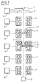
- the in the illuminating beam path for illuminating different sized light fields in The beam paths realized in each case on the plane of the specimen (6) are shown in FIG. 2.
- the source-side condenser lens (3) is strongly excited, so that this Condenser lens a greatly reduced, real image (C1) of the cross-over of the particle source generated.
- the image scale of this reduced cross-over image is approximately 1:20 to 1:50.
- the lens-side condenser lens (4) forms that of the first Condenser lens (3) generated a reduced image (C1) of the cross-over in the source side Focal plane of the condenser-objective single field lens, so that there is another intermediate image (C1 ') of the cross-over arises.
- the image scale for this second cross-over Mapping is about 1: 1. Due to the effect of the apron of the condenser lens single field lens (5) the illumination takes place in the specimen level (6) as for Condenser-objective single-field lenses usually due to rays parallel to the axis.
- Condenser lens (3) reduced while the excitation of the lens-side condenser lens (2) and of course the excitation of the condenser-objective single-field lens remains fixed. That from the Source-side condenser lens (3) generated cross-over image (C2) shifts after weakening the condenser lens (3) towards the lens side Condenser lens (4) with the result that this is also from the condenser lens on the lens side (4) generated image (C2 ') of the cross-over image (C2) in the direction of the condenser-objective single-field lens (5) moves. This results in the preparation level (6) Illumination of a smaller light field with divergent particle beams.
- the minimum light field is reached when the excitation of the source Condenser lens (3) is weakened to such an extent that both condenser lenses (3, 4) together an only slightly reduced image (C3) of the crossover of the particle source, namely in the conjugate with respect to the condenser-objective single-field lens (5) to the specimen plane (6) Level is generated.
- This level of the cross-over image (C3) is the input side Image plane of the condenser-objective single field lens (5), so that the condenser-objective single field lens (5) a reduced image (C3 ') of the cross-over image (C3) in the specimen plane (6) generated.
- the lighting and Imaging system in TEM operation always generates two cross-over images, whereby the second cross-over image (C1 ', C2', C3 ') between the source-side focal plane of the Condenser lens single-field lens and the specimen level is created.
- the generation of the second Cross-over images in the focal plane of the condenser lens single-field lens and in the Specimen level of the condenser-objective single-field lens (5) each represent the Limit settings at maximum or minimum light field diameter.
- apron aperture (5a) only at very small light field diameters limiting aperture.
- the opening diameter of the apron should be like this be chosen so that the maximum illumination aperture with a minimum light field is approximately 2.5 up to 3mrad. With larger light field diameters, the illumination aperture decreases and is extreme in the extreme case of axis-parallel illumination with a value of below 0.1mrad.
- both condenser lenses are operated as a zoom system.
- the beam path is shown with the smallest possible spot diameter.
- the source-side condenser lens (3) is set to its maximum excitation that the Excitation at maximum illuminated field diameter in TEM mode corresponds.
- the Accordingly, the source-side condenser lens produces a crossover that is 1: 30 times smaller Image (C4) of the particle source (1).
- the objective-side condenser lens (4) is used in this case so excited that it causes the cross-over generated by the source-side condenser lens (3) Image (C4) approximately on a scale of 1: 5 into that conjugated to the plane of the specimen (6) Plane that represents the image plane of the condenser-objective single-field lens (5) on the input side.
- Image (C4) approximately on a scale of 1: 5 into that conjugated to the plane of the specimen (6)
- Plane that represents the image plane of the condenser-objective single-field lens (5) on the input side.
- This conjugate level consequently creates a further intermediate crossover (C4 ').
- This further intermediate cross-over (C4 ') is performed by the condenser-objective single-field lens in the plane of the specimen (6) is shown so that there is another cross-over image (C4 '') arises. If the condenser-objective single-field lens remains unchanged, this way generate minimum probe sizes of approx. 7nm.
- the excitation of the two condenser lenses can (3, 4) are changed so that they always include the particle source (1) in the source side Form the image system of the condenser-objective single-field lens (5) imaging zoom system.
- the apron In order to achieve a maximum probe current with spot lighting, i.e. in STEM mode, is to change the apron to a diameter compared to the TEM mode of about 100-200 ⁇ m is required, from which lighting apertures in the range 5 - 20 mrad result.
- the apron can either be made of beryllium or close to the A condenser diaphragm (4a) is provided on the main plane of the condenser lens (4) on the lens side his.
Landscapes
- Chemical & Material Sciences (AREA)
- Analytical Chemistry (AREA)
- Microscoopes, Condenser (AREA)
- Electron Sources, Ion Sources (AREA)
Applications Claiming Priority (2)
| Application Number | Priority Date | Filing Date | Title |
|---|---|---|---|
| DE19945344A DE19945344A1 (de) | 1999-09-22 | 1999-09-22 | Teilchenoptisches Beleuchtungs- und Abbildungssystem mit einer Kondensor-Objektiv-Einfeldlinse |
| DE19945344 | 1999-09-22 |
Publications (3)
| Publication Number | Publication Date |
|---|---|
| EP1087420A2 true EP1087420A2 (fr) | 2001-03-28 |
| EP1087420A3 EP1087420A3 (fr) | 2001-04-18 |
| EP1087420B1 EP1087420B1 (fr) | 2005-06-15 |
Family
ID=7922859
Family Applications (1)
| Application Number | Title | Priority Date | Filing Date |
|---|---|---|---|
| EP00118942A Expired - Lifetime EP1087420B1 (fr) | 1999-09-22 | 2000-09-01 | Dispositif d'optique corpusculaire pour l'illumination et l'imagerie comprenant une lentille condenseur-objectif à champ unique et procédé de son utilisation |
Country Status (5)
| Country | Link |
|---|---|
| US (1) | US6531698B1 (fr) |
| EP (1) | EP1087420B1 (fr) |
| JP (1) | JP4615689B2 (fr) |
| CZ (1) | CZ301269B6 (fr) |
| DE (2) | DE19945344A1 (fr) |
Cited By (1)
| Publication number | Priority date | Publication date | Assignee | Title |
|---|---|---|---|---|
| EP1172837A3 (fr) * | 2000-07-14 | 2006-07-05 | LEO Elektronenmikroskopie GmbH | Procédé de lithographie par faisceau d'électrons et dispositif d'optique électronique pour la lithographie |
Families Citing this family (8)
| Publication number | Priority date | Publication date | Assignee | Title |
|---|---|---|---|---|
| US6787772B2 (en) * | 2000-01-25 | 2004-09-07 | Hitachi, Ltd. | Scanning electron microscope |
| DE10335504B4 (de) | 2003-07-31 | 2008-11-27 | Carl Zeiss Nts Gmbh | Elektronenstrahlgerät mit Präparathalter |
| DE102004037781A1 (de) | 2004-08-03 | 2006-02-23 | Carl Zeiss Nts Gmbh | Elektronenstrahlgerät |
| DE102006011615A1 (de) | 2006-03-14 | 2007-09-20 | Carl Zeiss Nts Gmbh | Phasenkontrast-Elektronenmikroskop |
| DE102010041813A1 (de) * | 2010-09-30 | 2012-04-05 | Carl Zeiss Nts Gmbh | Teilchenstrahlgerät und Verfahren zur Untersuchung und/oder Bearbeitung eines Objekts |
| JP6074760B2 (ja) * | 2012-09-13 | 2017-02-08 | 国立大学法人北海道大学 | 電子線照射装置 |
| JP6061771B2 (ja) * | 2013-04-25 | 2017-01-18 | 株式会社日立製作所 | 試料ホルダおよびそれを用いた荷電粒子線装置 |
| JP6995103B2 (ja) * | 2019-11-15 | 2022-01-14 | 日本電子株式会社 | 透過電子顕微鏡および透過電子顕微鏡の制御方法 |
Family Cites Families (8)
| Publication number | Priority date | Publication date | Assignee | Title |
|---|---|---|---|---|
| DE1614123B1 (de) * | 1967-02-24 | 1970-07-02 | Max Planck Gesellschaft | Korpuskularstrahlgeraet,insbesondere Elektronenmikroskop |
| NL175245C (nl) * | 1977-05-26 | 1984-10-01 | Philips Nv | Elektronenmicroscoop met hulplens en elektromagnetische lens hiervoor. |
| JPS60220541A (ja) | 1984-04-17 | 1985-11-05 | Jeol Ltd | 透過電子顕微鏡 |
| JPS6171539A (ja) * | 1984-09-13 | 1986-04-12 | Internatl Precision Inc | 電子線装置の照射系 |
| DE3825103A1 (de) * | 1988-07-23 | 1990-01-25 | Zeiss Carl Fa | Verfahren zum beleuchten eines objektes in einem transmissions-elektronenmikroskop |
| JPH06215714A (ja) * | 1992-06-05 | 1994-08-05 | Hitachi Ltd | 電界放出型透過電子顕微鏡 |
| DE4243489A1 (de) * | 1992-12-22 | 1994-06-23 | Zeiss Carl Fa | Verfahren zur Beleuchtung mit einem fokussierten Elektronenstrahl und zugehöriges elektronen-optisches Beleuchtungssystem |
| DE4328649A1 (de) * | 1993-08-26 | 1995-03-02 | Zeiss Carl Fa | Elektronenoptisches Abbildungssystem mit regelbaren Elementen |
-
1999
- 1999-09-22 DE DE19945344A patent/DE19945344A1/de not_active Withdrawn
-
2000
- 2000-09-01 EP EP00118942A patent/EP1087420B1/fr not_active Expired - Lifetime
- 2000-09-01 DE DE50010551T patent/DE50010551D1/de not_active Expired - Lifetime
- 2000-09-18 CZ CZ20003401A patent/CZ301269B6/cs not_active IP Right Cessation
- 2000-09-19 JP JP2000283163A patent/JP4615689B2/ja not_active Expired - Fee Related
- 2000-09-22 US US09/668,497 patent/US6531698B1/en not_active Expired - Lifetime
Cited By (1)
| Publication number | Priority date | Publication date | Assignee | Title |
|---|---|---|---|---|
| EP1172837A3 (fr) * | 2000-07-14 | 2006-07-05 | LEO Elektronenmikroskopie GmbH | Procédé de lithographie par faisceau d'électrons et dispositif d'optique électronique pour la lithographie |
Also Published As
| Publication number | Publication date |
|---|---|
| JP2001126652A (ja) | 2001-05-11 |
| CZ20003401A3 (en) | 2001-05-16 |
| CZ301269B6 (cs) | 2009-12-30 |
| JP4615689B2 (ja) | 2011-01-19 |
| EP1087420B1 (fr) | 2005-06-15 |
| DE50010551D1 (de) | 2005-07-21 |
| DE19945344A1 (de) | 2001-03-29 |
| EP1087420A3 (fr) | 2001-04-18 |
| US6531698B1 (en) | 2003-03-11 |
Similar Documents
| Publication | Publication Date | Title |
|---|---|---|
| DE102018007652B4 (de) | Teilchenstrahl-System sowie Verfahren zur Stromregulierung von Einzel-Teilchenstrahlen | |
| EP0333018B1 (fr) | Lentille d'objectif pour la focalisation de particules chargées | |
| EP1277221B1 (fr) | Canon electronique pour electrons ou faisceaux ioniques de haute monochromie ou de haute densite de courant | |
| EP2278607B1 (fr) | Appareil à faisceau de particules chargées avec unité d'ouverture et procédé de réglage d'un courant de faisceau dans un appareil à faisceau de particules chargées | |
| EP0352552B1 (fr) | Procédé d'éclairement d'un objet dans un microscope électronique à transmission et microscope électronique apte à la mise en ouvre du procédé | |
| DE102015210941B4 (de) | Teilchenstrahlgerät und Verfahren zum Betrieb eines Teilchenstrahlgeräts | |
| EP1835523A2 (fr) | Microscope à électrons à contraste de phase | |
| DE112016005577B4 (de) | Ladungsträgerstrahlvorrichtung und Verfahren zur Einstellung ihrer optischen Achse | |
| EP0899771B1 (fr) | Filtre en énergie, en particulier pour microscope électronique | |
| EP0166328A2 (fr) | Procédé et dispositif pour produire l'image d'un objet ou du diagramme de diffraction d'un objet par filtrage d'énergie des électrons avec un microscope électronique à transmission | |
| EP0893816A2 (fr) | Appareil à faisceau corpusculaire | |
| DE2702445A1 (de) | Korpuskularstrahloptisches geraet zur verkleinernden abbildung einer maske auf ein zu bestrahlendes praeparat | |
| DE69920182T2 (de) | Korpuskularstrahloptisches gerät mit auger-elektronendetektion | |
| EP1187169A2 (fr) | Composants d'optique corpusculaire et dispositif comportant de tels composants | |
| EP0194570A2 (fr) | Microscope corpusculaire à balayage à effet Boersch réduit | |
| EP0603555B1 (fr) | Procédé d'illumination par un faisceau d'électron focalisé et système d'optique électronique d'illumination pour la mise en oeuvre dudit procédé | |
| EP1087420B1 (fr) | Dispositif d'optique corpusculaire pour l'illumination et l'imagerie comprenant une lentille condenseur-objectif à champ unique et procédé de son utilisation | |
| DE2430696A1 (de) | Elektronenmikroskop | |
| EP1642313A2 (fr) | Systeme de detecteurs pour un microscope electronique a balayage et microscope electronique a balayage pourvu d'un systeme de detecteurs correspondant | |
| DE19746785A1 (de) | Teilchenstrahlgerät mit Energiefilter | |
| DE102015210893B4 (de) | Analyseeinrichtung zur Analyse der Energie geladener Teilchen und Teilchenstrahlgerät mit einer Analyseeinrichtung | |
| DE10217507A1 (de) | Anordnung zur Abbildung des von einer Probe gepulst emittierten Teilchenensembles auf einem Detektor | |
| DE10190535B4 (de) | Emissionselektronenmikroskop | |
| DE102004019835B4 (de) | Beleuchtungskondensor für ein Partikeloptik-Projektionssystem | |
| DE2043749A1 (de) | Raster Korpuskularstrahlmikroskop |
Legal Events
| Date | Code | Title | Description |
|---|---|---|---|
| PUAI | Public reference made under article 153(3) epc to a published international application that has entered the european phase |
Free format text: ORIGINAL CODE: 0009012 |
|
| PUAL | Search report despatched |
Free format text: ORIGINAL CODE: 0009013 |
|
| AK | Designated contracting states |
Kind code of ref document: A2 Designated state(s): DE NL |
|
| AX | Request for extension of the european patent |
Free format text: AL;LT;LV;MK;RO;SI |
|
| AK | Designated contracting states |
Kind code of ref document: A3 Designated state(s): AT BE CH CY DE DK ES FI FR GB GR IE IT LI LU MC NL PT SE |
|
| AX | Request for extension of the european patent |
Free format text: AL;LT;LV;MK;RO;SI |
|
| 17P | Request for examination filed |
Effective date: 20010907 |
|
| AKX | Designation fees paid |
Free format text: DE NL |
|
| 17Q | First examination report despatched |
Effective date: 20040311 |
|
| RTI1 | Title (correction) |
Free format text: DEVICE FOR PARTICLE-OPTICAL ILLUMINATION AND IMAGING COMPRISING A SINGLE FIELD CONDENSOR-OJECTIVE LENS AND METHOD OF OPER |
|
| GRAP | Despatch of communication of intention to grant a patent |
Free format text: ORIGINAL CODE: EPIDOSNIGR1 |
|
| GRAS | Grant fee paid |
Free format text: ORIGINAL CODE: EPIDOSNIGR3 |
|
| GRAA | (expected) grant |
Free format text: ORIGINAL CODE: 0009210 |
|
| RAP1 | Party data changed (applicant data changed or rights of an application transferred) |
Owner name: CARL ZEISS NTS GMBH |
|
| AK | Designated contracting states |
Kind code of ref document: B1 Designated state(s): DE NL |
|
| REF | Corresponds to: |
Ref document number: 50010551 Country of ref document: DE Date of ref document: 20050721 Kind code of ref document: P |
|
| PLBE | No opposition filed within time limit |
Free format text: ORIGINAL CODE: 0009261 |
|
| STAA | Information on the status of an ep patent application or granted ep patent |
Free format text: STATUS: NO OPPOSITION FILED WITHIN TIME LIMIT |
|
| 26N | No opposition filed |
Effective date: 20060316 |
|
| REG | Reference to a national code |
Ref country code: DE Ref legal event code: R081 Ref document number: 50010551 Country of ref document: DE Owner name: CARL ZEISS MICROSCOPY GMBH, DE Free format text: FORMER OWNER: CARL ZEISS NTS GMBH, 73447 OBERKOCHEN, DE Effective date: 20130319 |
|
| PGFP | Annual fee paid to national office [announced via postgrant information from national office to epo] |
Ref country code: DE Payment date: 20140922 Year of fee payment: 15 |
|
| PGFP | Annual fee paid to national office [announced via postgrant information from national office to epo] |
Ref country code: NL Payment date: 20140918 Year of fee payment: 15 |
|
| REG | Reference to a national code |
Ref country code: DE Ref legal event code: R119 Ref document number: 50010551 Country of ref document: DE |
|
| REG | Reference to a national code |
Ref country code: NL Ref legal event code: MM Effective date: 20151001 |
|
| PG25 | Lapsed in a contracting state [announced via postgrant information from national office to epo] |
Ref country code: DE Free format text: LAPSE BECAUSE OF NON-PAYMENT OF DUE FEES Effective date: 20160401 |
|
| PG25 | Lapsed in a contracting state [announced via postgrant information from national office to epo] |
Ref country code: NL Free format text: LAPSE BECAUSE OF NON-PAYMENT OF DUE FEES Effective date: 20151001 |