EP1087440A2 - Augmentation de la fiabilite par une technique de modelage - Google Patents
Augmentation de la fiabilite par une technique de modelage Download PDFInfo
- Publication number
- EP1087440A2 EP1087440A2 EP00307830A EP00307830A EP1087440A2 EP 1087440 A2 EP1087440 A2 EP 1087440A2 EP 00307830 A EP00307830 A EP 00307830A EP 00307830 A EP00307830 A EP 00307830A EP 1087440 A2 EP1087440 A2 EP 1087440A2
- Authority
- EP
- European Patent Office
- Prior art keywords
- row
- balls
- grid array
- ball
- technique
- Prior art date
- Legal status (The legal status is an assumption and is not a legal conclusion. Google has not performed a legal analysis and makes no representation as to the accuracy of the status listed.)
- Withdrawn
Links
Images


Classifications
-
- H—ELECTRICITY
- H05—ELECTRIC TECHNIQUES NOT OTHERWISE PROVIDED FOR
- H05K—PRINTED CIRCUITS; CASINGS OR CONSTRUCTIONAL DETAILS OF ELECTRIC APPARATUS; MANUFACTURE OF ASSEMBLAGES OF ELECTRICAL COMPONENTS
- H05K1/00—Printed circuits
- H05K1/02—Details
- H05K1/11—Printed elements for providing electric connections to or between printed circuits
- H05K1/111—Pads for surface mounting, e.g. lay-out
- H05K1/112—Pads for surface mounting, e.g. lay-out directly combined with via connections
-
- H—ELECTRICITY
- H10—SEMICONDUCTOR DEVICES; ELECTRIC SOLID-STATE DEVICES NOT OTHERWISE PROVIDED FOR
- H10W—GENERIC PACKAGES, INTERCONNECTIONS, CONNECTORS OR OTHER CONSTRUCTIONAL DETAILS OF DEVICES COVERED BY CLASS H10
- H10W70/00—Package substrates; Interposers; Redistribution layers [RDL]
- H10W70/60—Insulating or insulated package substrates; Interposers; Redistribution layers
- H10W70/62—Insulating or insulated package substrates; Interposers; Redistribution layers characterised by their interconnections
- H10W70/65—Shapes or dispositions of interconnections
-
- H—ELECTRICITY
- H05—ELECTRIC TECHNIQUES NOT OTHERWISE PROVIDED FOR
- H05K—PRINTED CIRCUITS; CASINGS OR CONSTRUCTIONAL DETAILS OF ELECTRIC APPARATUS; MANUFACTURE OF ASSEMBLAGES OF ELECTRICAL COMPONENTS
- H05K2201/00—Indexing scheme relating to printed circuits covered by H05K1/00
- H05K2201/09—Shape and layout
- H05K2201/09209—Shape and layout details of conductors
- H05K2201/09218—Conductive traces
- H05K2201/09227—Layout details of a plurality of traces, e.g. escape layout for Ball Grid Array [BGA] mounting
-
- H—ELECTRICITY
- H05—ELECTRIC TECHNIQUES NOT OTHERWISE PROVIDED FOR
- H05K—PRINTED CIRCUITS; CASINGS OR CONSTRUCTIONAL DETAILS OF ELECTRIC APPARATUS; MANUFACTURE OF ASSEMBLAGES OF ELECTRICAL COMPONENTS
- H05K2201/00—Indexing scheme relating to printed circuits covered by H05K1/00
- H05K2201/10—Details of components or other objects attached to or integrated in a printed circuit board
- H05K2201/10613—Details of electrical connections of non-printed components, e.g. special leads
- H05K2201/10621—Components characterised by their electrical contacts
- H05K2201/10734—Ball grid array [BGA]; Bump grid array
-
- H—ELECTRICITY
- H05—ELECTRIC TECHNIQUES NOT OTHERWISE PROVIDED FOR
- H05K—PRINTED CIRCUITS; CASINGS OR CONSTRUCTIONAL DETAILS OF ELECTRIC APPARATUS; MANUFACTURE OF ASSEMBLAGES OF ELECTRICAL COMPONENTS
- H05K3/00—Apparatus or processes for manufacturing printed circuits
- H05K3/0005—Apparatus or processes for manufacturing printed circuits for designing circuits by computer
-
- H—ELECTRICITY
- H10—SEMICONDUCTOR DEVICES; ELECTRIC SOLID-STATE DEVICES NOT OTHERWISE PROVIDED FOR
- H10W—GENERIC PACKAGES, INTERCONNECTIONS, CONNECTORS OR OTHER CONSTRUCTIONAL DETAILS OF DEVICES COVERED BY CLASS H10
- H10W72/00—Interconnections or connectors in packages
- H10W72/851—Dispositions of multiple connectors or interconnections
- H10W72/874—On different surfaces
- H10W72/884—Die-attach connectors and bond wires
-
- H—ELECTRICITY
- H10—SEMICONDUCTOR DEVICES; ELECTRIC SOLID-STATE DEVICES NOT OTHERWISE PROVIDED FOR
- H10W—GENERIC PACKAGES, INTERCONNECTIONS, CONNECTORS OR OTHER CONSTRUCTIONAL DETAILS OF DEVICES COVERED BY CLASS H10
- H10W90/00—Package configurations
- H10W90/701—Package configurations characterised by the relative positions of pads or connectors relative to package parts
- H10W90/731—Package configurations characterised by the relative positions of pads or connectors relative to package parts of die-attach connectors
- H10W90/734—Package configurations characterised by the relative positions of pads or connectors relative to package parts of die-attach connectors between a chip and a stacked insulating package substrate, interposer or RDL
-
- H—ELECTRICITY
- H10—SEMICONDUCTOR DEVICES; ELECTRIC SOLID-STATE DEVICES NOT OTHERWISE PROVIDED FOR
- H10W—GENERIC PACKAGES, INTERCONNECTIONS, CONNECTORS OR OTHER CONSTRUCTIONAL DETAILS OF DEVICES COVERED BY CLASS H10
- H10W90/00—Package configurations
- H10W90/701—Package configurations characterised by the relative positions of pads or connectors relative to package parts
- H10W90/751—Package configurations characterised by the relative positions of pads or connectors relative to package parts of bond wires
- H10W90/754—Package configurations characterised by the relative positions of pads or connectors relative to package parts of bond wires between a chip and a stacked insulating package substrate, interposer or RDL
Definitions
- the present invention relates to the field of integrated circuit devices. More specifically, but not exclusively, the present invention relates to a modeling technique for selectively depopulating electrical contacts from a foot print of a grid array (ball grid array (BGA) or land grid array (LGA)) package to increase the routability of the package substrate and increase the device reliability.
- BGA ball grid array
- LGA land grid array
- CSPs chip scale packages
- CSPs are in many ways an ideal solution to the cost reduction and miniaturization requirement. They offer enormous area reductions compared with quad flat package, and have increasing potential to do so without adding system level cost. In the best case, CSPs are able to compete today, on a cost per terminal basis, with quad flat packages. For example, various CSPs from Texas Instruments are now available at cost parity with thin quad flat packages.
- Texas Instruments produces a polyimide-based family of CSPs known as MicroStarBGATM (see Figure 1) .
- This CSP 10 like most others, uses solder alloy balls 12 as the interconnection between the package substrate 14 and the board on which the packages is soldered. As with all such packages, the solder balls formed between the package and the board are susceptible to fatigue when exposed to cyclic ambient temperature conditions.
- JEDEC and EIAJ are increasingly documenting fine pitch BGA industry standards.
- the finest pitch standard that is currently widely recognized is 0.50mm pitch.
- broad acceptance and use of 0.50mm pitch CSPs is still very limited, due to the following reasons:
- Figure 4 discloses a conventional ball footprint (regular pattern of 3 row of balls) having 144 balls (on a 0.5 mm pitch) on a 10x10mm package body. To achieve this dense routing, a designer has to compromise. There are typically three options:
- Figure 5 discloses a routing pattern for 3 full rows of balls, in which:
- An embodiment of the invention provides a modeling technique for selectively depopulating solder contacts (and their respective contact pads, vias and traces or lines) from a conventional foot print of a grid array package (Ball Grid Array (BGA), or Land Grid Array (LGA)) to improve device reliability, and a BGA or LGA package so modeled.
- the modeling technique anticipates a routing of traces through the gap resulting from the depopulated solder contacts as additional space for routing traces or lines from solder contact pads to an exterior surface of a substrate (14) upon which a semiconductor die (20) is mounted.
- An advantage of an embodiment of the present invention is that it provides an easy to use modeling technique (e.g., in this case an Excel spreadsheet) that allows a user to easily predict whether or not a preselected number of balls on a specific body size device will be possible.
- a 280 um via (32) only permits one trace between adjacent balls (12). If however, we depopulate a ball (including its associated via (32), solder ball pad (34) and trace or line (30)), we can now place up to 8 traces or lines (30) when using the 25um rule-line/space 28/42 (or up to 13 traces or lines (30) when using the 18um rule-line/space 20/30 - these numbers will change when other rule-line/space numbers are selected) in the resulting gap between 2 adjacent balls. By careful selection of these depopulated balls, it is possible to route as many, if not more total balls with the optimum design rule (optimum via diameter), as compared to the conventional footprint with compromised design rules (e.g., via diameter of less than 280 um) . This design concept is called 'Smart-Foot'TM, .
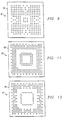
- Figure 6 illustrates a footprint (38), with selective ball depopulation. More specifically, the selective ball depopulated footprint (38) shown in Figure 6 is a footprint for the TI 151 GHZ uStarBGA TM, package, which comprises 151 balls on a 10x10 mm body (40).
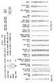
- Figure 7 discloses an Excel spreadsheet incorporating a modeling technique that allows a package designer to quickly determine whether or not a preselected number of balls for a specific body size is feasible. In order for the modeling technique to work, there are some parameter that have to be preselected (or inserted into the spreadsheet's calculation rules) and others that can be entered "on the fly" by a designer.
- a 0.50mm pitch is preselected which is the largest possible matrix with n-1 row depopulated.
- a Viacap rule of 50 um is also preselected which is an overlap of metal from the edge of the via.
- the body size parameter is one which a designer next selects "on the fly” (10mm in the case of Figure 7).
- the matrix parameter is also selected “on the fly” (18 in the case of Figure 7).
- the Ball Pitch is preselected (500um in the case of Figure 7). Next, there are 17 vertical columns of information that must be filled in - most preselected, but a few "on the fly".
- Column 1 is the "Row n-" column. It lists at least the total number of possible rows (four-sided) for the selected body size, starting with “row 0" as the outer most (and therefore largest) row and working up to "row n” as the inner most (and therefore smallest row). While 11 rows are listed (0-10), 9 are the most available in the case of Figure 7. The total number of rows is preselected and will vary depending upon body size and matrix selected.
- Column 2 is the "Ballsites/row” column. Column 2 lists the total possible number of ball sites available for each specific row. While the number for each row is initially preselected, the program will automatically change the numbers as the body and matrix number are changed "on the fly" by a designer. In the case of Figure 7 (10mm body size and matrix of 18), row 0 lists 68 ball sites available. Each additional row lists a correspondingly reduced number of ball sites until row 8, which lists 4 ball sites available. Being that the spreadsheet was designed with substrate design rules in mind (knowledge available to one of ordinary skill in the art), these numbers are changed by the spreadsheet and not by a device designer.
- Column 3 is the "Balls depopulated per side" of a four-sided row. These are selected by a designer "on the fly”. A designer can select from 0 to a full 1/4 of the total number of ball sites, to depopulate on each row.
- Column 4 is the "Remaining balls on row” column which lists the total number of balls remaining in the respective four-sided row. While these numbers will be initially preselected to be the same as their respective “ballsites/row” assuming 0 balls depopulated per side, the spreadsheet will automatically change the numbers as a designer changes the numbers in Column 3 "on the fly”.
- Column 5 is the "Number of reduced size vias/Side”. The numbers in this column are preselected by a designer should be 0 for each row having standard size vias. This number is preset by the design rules and will not change unless the designer prechooses a nonstandard via size.
- Column 8 is the "Reduced via size (um)" column.
- the numbers in this column are preselected by a designer and, if reduced vias are to be used in conjunction with standard size vias, then the designer must prechoose the reduced size. If no reduced size vias are to be selected, then the number should be left the same as in Column 7.
- Column 9 is the "Line width (um)" column.
- the numbers in this column are preselected by a designer and, if the 18um copper rule is selected, the number placed in each row of column 9 is 18. If by change the 25 um copper rule is selected, 28 is the number placed in each row of column 9. While the current invention contemplates two rules to choose from, e.g., the 18 um and 25 um rules for line/space, other can also be used.
- Column 10 is the "Space width (um)" column.
- the numbers in this column are preselected by a designer and, if the 18 um copper rule is selected, the number placed in each row of column 10 is 28. If, on the other hand, the 25 um copper rule is selected, 42 is the number placed in each row of column 10. While the current invention contemplates two rules to choose from, e.g., the 18 um and 25 um rules for line/space, other can also be used.
- Column 11 is the "Traces between standard vias" column.
- the numbers in this column are preselected by a designer and, under currently accepted industry standards, if the 18um line/space rule is selected, 2 is preselected and placed in each row of column 11. If, on the other hand, the 25um line/space rule is selected, 1 is preselected and placed in each row of column 11. As above, this number may change for other line/spacing rules or as industry standards change.
- Column 12 is the "Traces per depopulated ball" column. The numbers in this column are preselected by a designer and, under currently accepted industry spacing standards, if the 18um rule is selected, up to 12 traces per depopulated ball are possible. If the 25um line/spacing rule is selected, up to 8 traces per depopulated ball are possible. As above, this number may change for other line/spacing rules or as industry standards change.
- Column 13 is the "Max traces (balls inside) column. This calculates the total number of metal traces that can be placed between the balls (with or without depopulation) on the given row. This equates to the maximum number of balls that can be placed on the sum of all the rows inside the given row.
- Column 14 is the "Max Traces OK?” column. This checks that the number of allowable traces between the balls on the given column is sufficient to accommodate all the balls currently specified as present on the sum of the rows inside the given row. If not, a warning value of -99999 is calculated, resulting in a non-workable solution. If this non-workable solution is flagged, then more balls can be depopulated in column 3 until a workable solution is found.
- Column 15 is the "Total Possible Balls” column. This shows the number of balls on the given row, if the result in column 14 is workable. If not, it shows the value zero, and subsequently indicates a non-workable total (zero) in the "TOTAL" cell.
- Column 16 is the "Actual Balls Inside” column. This shows the total number of balls currently present inside the given row. This is compared to the theoretical maximum balls possible shown in column 13. If the actual is less than the theoretical maximum, this indicates a workable solution, and is used to calculate the difference between theoretical and actual in column 17.
- Column 17 is the "Delta” column. This calculates the difference between the actual balls inside the given row, and the theoretical maximum number of balls possible inside the given row. The closer to zero, the more difficult the routing is likely to be.
- the outer most row (row 0) on the gird has a maximum potential of 68 ball sites with 6 balls being depopulated on each of the four sides of the outermost row, resulting in a total number of 44 balls remaining for row 0.
- the next row in on the grid (row 1) has a maximum potential of 60 ball sites with 14 balls being depopulated on each of the four sides of the row, resulting in a total number of 4 balls remaining for row 1.
- the next row in on the grid (row 2) has a maximum potential of 52 ball sites with 0 balls being depopulated on each of the four sides of the row, resulting in a total number of 52 balls remaining on row 2.
- the next row in on the grid (row 3) has a maximum potential of 44 ball sites with 0 balls being depopulated on each of the four sides of the row, resulting in a total number of 44 balls remaining on row 3.
- the next row in on the grid (row 4) has a maximum potential of 36 ball sites with 7 balls being depopulated on each of the four sides of the row, resulting in a total number of 44 balls remaining on row 3. No additional rows of ball were selected. Adding all of the balls together results in a package having a footprint with 152 balls (reduced to 151 balls when the ball in the lower left had corner of row 0 is depopulated), as can be seen in Figure 7, which illustrates the results of the selection for this footprint.
- the 151 balls actually selected are not the maximum or minimum that can be obtained for a 10x10 mm package using the selective depopulation of the present teaching. Nevertheless, 151 balls is substantially more than can be obtained on a 10x10 mm package using conventional footprint design techniques requiring the optimum 280 um via size.
- Figure 8 illustrates a routing pattern of a portion of the footprint of Figure 6 along section lines 1-1. The spreadsheet indicates in fact that up to 248 balls could be routed with 280um vias if required (by depopulating on rows 0-5, 6,5,4,2,1 and 1 balls respectively).
- Figure 9 illustrates another footprint (41), with selective ball depopulation. More specifically, the selective ball depopulated footprint (41) shown in Figure 9 is a footprint for the TI 240 GHZ uStarBGA TM, package, which comprises 240 balls on a 10x10 mm body (40).
- the TI 240 GHZ uStarBGA TM, package modeling began with the selection of a 10x10 mm body (based upon combination of size of die and size limitation request of customer). Next a ball grid matrix of 17 (17x17) was selected.
- the outer most row (row 0) on the gird has a maximum potential of 64 ball sites with 3 balls being depopulated on each of the four sides of the outermost row, resulting in a total number of 52 balls remaining for row 0.
- the next row in on the grid (row 1) has a maximum potential of 56 ball sites with 2 balls being depopulated on each of the four sides of the row, resulting in a total number of 48 balls remaining for row 1.
- the next row in on the grid (row 2) has a maximum potential of 48 ball sites with 2 balls being depopulated on each of the four sides of the row, resulting in a total number of 40 balls remaining on row 2.
- the next row in on the grid (row 3) has a maximum potential of 40 ball sites with 1 ball being depopulated on each of the four sides of the row, resulting in a total number of 36 balls remaining on row 3.
- the next row in on the grid (row 4) has a maximum potential of 32 ball sites with 0 balls being depopulated on each of the four sides of the row, resulting in a total number of 32 balls remaining on row 4.
- the next row in on the grid (row 5) has a maximum potential of 24 ball sites with 0 balls being depopulated on each of the four sides of the row, resulting in a total number of 24 balls remaining on row 5.
- the next row in on the grid (row 6) has a maximum potential of 16 ball sites with 4 balls being depopulated on each of the four sides of the row, resulting in a total number of 0 balls remaining on row 6.
- the next row in on the grid (row 7) has a maximum potential of 8 ball sites with 0 balls being depopulated on each of the four sides of the row, resulting in a total number of 8 balls remaining on row 7. No additional rows of ball were selected. Adding all of the balls together results in a package having a footprint with 240 balls, as can be seen in Figure 10, which illustrates the results of the selection for this footprint.
- the 240 balls actually selected are not the maximum or minimum that can be obtained for a 10x10 mm package using the selective depopulation of the present teaching. As above, 240 balls is substantially more than can be obtained on a 10x10 mm package using conventional footprint design techniques requiring the optimum 280 um via size.
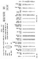
- Figure 11 illustrates yet another footprint (43), with selective ball depopulation. More specifically, the selective ball depopulated footprint (43) shown in Figure 11 is a footprint for the TI 288 GZG uStarBGA TM, package, which comprises 288 balls on a 12x12 mm body (45).
- the TI 288 GZG uStarBGA TM, package modeling began with the selection of a 12x12 mm body (based upon combination of size of die and size limitation request of customer). Next a ball grid matrix of 21 (21x21) was selected.
- the outer most row (row 0) on the gird has a maximum potential of 80 ball sites with 8 balls being depopulated on each of the four sides of the outermost row, resulting in a total number of 48 balls remaining for row 0.
- the next row in on the grid (row 1) has a maximum potential of 72 ball sites with 1 ball being depopulated on each of the four sides of the row, resulting in a total number of 68 balls remaining for row 1.
- the next row in on the grid (row 2) has a maximum potential of 64 ball sites with 0 balls being depopulated on each of the four sides of the row, resulting in a total number of 64 balls remaining on row 2.
- the next row in on the grid (row 3) has a maximum potential of 56 ball sites with 0 balls being depopulated on each of the four sides of the row, resulting in a total number of 56 balls remaining on row 3.
- the next row in on the grid (row 4) has a maximum potential of 48 ball sites with 12 balls being depopulated on each of the four sides of the row, resulting in a total number of 0 balls remaining on row 4.
- the next row in on the grid (row 5) has a maximum potential of 40 ball sites with 10 balls being depopulated on each of the four sides of the row, resulting in a total number of 0 balls remaining on row 5.
- the next row in on the grid (row 6) has a maximum potential of 32 ball sites with 1 ball being depopulated on each of the four sides of the row, resulting in a total number of 28 balls remaining on row 6.
- the next row in on the grid (row 7) has a maximum potential of 24 ball sites with 0 balls being depopulated on each of the four sides of the row, resulting in a total number of 24 balls remaining on row 7.
- the next row in on the grid (row 8) has a maximum potential of 16 ball sites with 4 balls being depopulated on each of the four sides of the row, resulting in a total number of 0 balls remaining on row 8.
- the next row in on the grid (row 9) has a maximum potential of 8 ball sites with 2 balls being depopulated on each of the four sides of the row, resulting in a total number of 0 balls remaining on row 9. No additional rows of ball were selected.
- Adding all of the balls together results in a package having a footprint with 288 balls, as can be seen in Figure 12, which illustrates the results of the selection for this footprint.
- the 288 balls actually selected are not the maximum or minimum that can be obtained for a 12x12 mm package using the selective depopulation of the present teaching. As above, 288 balls is substantially more than can be obtained on a 12x12 mm package using conventional footprint design techniques requiring the optimum 280 um via size.
- Figure 13 illustrates still another footprint (47), with selective ball depopulation. More specifically, the selective ball depopulated footprint (47) shown in Figure 11 is a footprint for the TI 240 GZG uStarBGA TM, package, which comprises 240 balls on a 12x12 mm body (45).
- the TI 240 GZG uStarBGA TM, package modeling began with the selection of a 12x12 mm body (based upon combination of size of die and size limitation request of customer). Next a ball grid matrix of 21 (21x21) was selected.
- the outer most row (row 0) on the gird has a maximum potential of 80 ball sites with 8 balls being depopulated on each of the four sides of the outermost row, resulting in a total number of 48 balls remaining for row 0.
- the next row in on the grid (row 1) has a maximum potential of 72 ball sites with 1 ball being depopulated on each of the four sides of the row, resulting in a total number of 68 balls remaining for row 1.
- the next row in on the grid (row 2) has a maximum potential of 64 ball sites with 2 balls being depopulated on each of the four sides of the row, resulting in a total number of 56 balls remaining on row 2.
- the next row in on the grid (row 3) has a maximum potential of 56 ball sites with 4 balls being depopulated on each of the four sides of the row, resulting in a total number of 40 balls remaining on row 3.
- the next row in on the grid (row 4) has a maximum potential of 48 ball sites with 12 balls being depopulated on each of the four sides of the row, resulting in a total number of 0 balls remaining on row 4.
- the next row in on the grid (row 5) has a maximum potential of 40 ball sites with 10 balls being depopulated on each of the four sides of the row, resulting in a total number of 0 balls remaining on row 5.
- the next row in on the grid (row 6) has a maximum potential of 32 ball sites with 1 ball being depopulated on each of the four sides of the row, resulting in a total number of 28 balls remaining on row 6.
- the next row in on the grid (row 7) has a maximum potential of 24 ball sites with 6 balls being depopulated on each of the four sides of the row, resulting in a total number of 0 balls remaining on row 7.
- the next row in on the grid (row 8) has a maximum potential of 16 ball sites with 4 balls being depopulated on each of the four sides of the row, resulting in a total number of 0 balls remaining on row 8.
- the next row in on the grid (row 9) has a maximum potential of 8 ball sites with 2 balls being depopulated on each of the four sides of the row, resulting in a total number of 0 balls remaining on row 9. No additional rows of ball were selected.
- Adding all of the balls together results in a package having a footprint with 240 balls, as can be seen in Figure 14, which illustrates the results of the selection for this footprint.
- the 240 balls actually selected are not the maximum or minimum that can be obtained for a 12x12 mm package using the selective depopulation of the present teaching. As above, 240 balls is substantially more than can be obtained on a 12x12 mm package using conventional footprint design techniques requiring the optimum 280 um via size.
- Figure 15 illustrates still yet another footprint (49), with selective ball depopulation. More specifically, the selective ball depopulated footprint (49) shown in Figure 15 is a footprint for the TI 256 GZG uStarBGA TM, package, which comprises 256 balls on a 12x12 mm body (45).
- the TI 256 GZG uStarBGA TM, package modeling began with the selection of a 12x12 mm body (based upon combination of size of die and size limitation request of customer). Next a ball grid matrix of 21 (21x21) was selected.
- the outer most row (row 0) on the gird has a maximum potential of 80 ball sites with 8 balls being depopulated on each of the four sides of the outermost row, resulting in a total number of 48 balls remaining for row 0.
- the next row in on the grid (row 1) has a maximum potential of 72 ball sites with 1 ball being depopulated on each of the four sides of the row, resulting in a total number of 68 balls remaining for row 1.
- the next row in on the grid (row 2) has a maximum potential of 64 ball sites with 0 balls being depopulated on each of the four sides of the row, resulting in a total number of 64 balls remaining on row 2.
- the next row in on the grid (row 3) has a maximum potential of 56 ball sites with 2 balls being depopulated on each of the four sides of the row, resulting in a total number of 48 balls remaining on row 3.
- the next row in on the grid (row 4) has a maximum potential of 48 ball sites with 12 balls being depopulated on each of the four sides of the row, resulting in a total number of 0 balls remaining on row 4.
- the next row in on the grid (row 5) has a maximum potential of 40 ball sites with 10 balls being depopulated on each of the four sides of the row, resulting in a total number of 0 balls remaining on row 5.
- the next row in on the grid (row 6) has a maximum potential of 32 ball sites with 1 ball being depopulated on each of the four sides of the row, resulting in a total number of 28 balls remaining on row 6.
- the next row in on the grid (row 7) has a maximum potential of 24 ball sites with 6 balls being depopulated on each of the four sides of the row, resulting in a total number of 0 balls remaining on row 7.
- the next row in on the grid (row 8) has a maximum potential of 16 ball sites with 4 balls being depopulated on each of the four sides of the row, resulting in a total number of 0 balls remaining on row 8.
- the next row in on the grid (row 9) has a maximum potential of 8 ball sites with 2 balls being depopulated on each of the four sides of the row, resulting in a total number of 0 balls remaining on row 9. No additional rows of ball were selected.
- Adding all of the balls together results in a package having a footprint with 256 balls, as can be seen in Figure 16, which illustrates the results of the selection for this footprint.
- the 256 balls actually selected are not the maximum or minimum that can be obtained for a 12x12 mm package using the selective depopulation of the present teaching. As above, 256 balls is substantially more than can be obtained on a 12x12 mm package using conventional footprint design techniques requiring the optimum 280 um via size.
- Table 1 shows the results of the board level reliability (BLR) tests done on both the conventional and 'smart footprints'. Due to the heavy dependence of die size on reliability, the die in both cases was kept constant (6.0x6.0mm). In order to focus on the package reliability, only failures in the package side of the joint are reported: Board level reliability of conventional and 'Smart-Foot'TM packages. Via Diameter (mm) Sample Size Cycles to first failure Conventional Footprint 0.212 28 550 'Smart-Foot'TM Footprint 0.280 31 1450
- the ability to model proposed solutions is invaluable in bringing new packages to market quickly.
- the TI 151 CSP 'Smart-Foot'TM packages was modeled using a two-dimensional finite element analysis tool before any new tooling was committed. The model confirmed the proposed reliability benefit in advance.
- the 151 ball CSP 'Smart-Foot'TM package not only proved as reliable as the model predicted, but all reliability tests passed first time.
- Figure 13 shows the worst case elastic strain prediction for both packages as a function of die size, and clearly shows a much lower strain in the case of the 'Smart-Foot'TM package.
- the 144 TQFP package has been a high running package for these applications.
- the 0.50mm pitch version with a 10x10mm body size needed to be developed.
- a software-controlled programmable processing device such as a Digital Signal Processor, microprocessor, other processing devices, data processing apparatus or computer system
- a computer program for configuring a programmable device, apparatus or system to implement the foregoing described modelling techniques is envisaged as an aspect of the present invention.
- the computer program may be embodied as source code and undergo compilation for implementation on a processing device, apparatus or system, or may be embodied as object code.
- object code The skilled person would readily understand that the term computer in its most general sense encompasses programmable devices such as referred to above, and data processing apparatus and computer systems.
- the computer program is stored on a carrier medium in machine or device readable form, for example in solid-state memory or magnetic memory such as disc or tape and the processing device utilises the program or a part thereof to configure it for operation.
- the computer program may be supplied from a remote source embodied in a communications medium such as an electronic signal, radio frequency carrier wave or optical carrier wave.
- a communications medium such as an electronic signal, radio frequency carrier wave or optical carrier wave.
- carrier media are also envisaged as aspects of the present invention.
Landscapes
- Engineering & Computer Science (AREA)
- Microelectronics & Electronic Packaging (AREA)
- Electric Connection Of Electric Components To Printed Circuits (AREA)
Applications Claiming Priority (2)
| Application Number | Priority Date | Filing Date | Title |
|---|---|---|---|
| US09/400,811 US6689634B1 (en) | 1999-09-22 | 1999-09-22 | Modeling technique for selectively depopulating electrical contacts from a foot print of a grid array (BGA or LGA) package to increase device reliability |
| US400811 | 1999-09-22 |
Publications (2)
| Publication Number | Publication Date |
|---|---|
| EP1087440A2 true EP1087440A2 (fr) | 2001-03-28 |
| EP1087440A3 EP1087440A3 (fr) | 2004-11-10 |
Family
ID=23585125
Family Applications (1)
| Application Number | Title | Priority Date | Filing Date |
|---|---|---|---|
| EP00307830A Withdrawn EP1087440A3 (fr) | 1999-09-22 | 2000-09-11 | Augmentation de la fiabilite par une technique de modelage |
Country Status (4)
| Country | Link |
|---|---|
| US (1) | US6689634B1 (fr) |
| EP (1) | EP1087440A3 (fr) |
| JP (1) | JP2001160602A (fr) |
| TW (1) | TW544878B (fr) |
Cited By (11)
| Publication number | Priority date | Publication date | Assignee | Title |
|---|---|---|---|---|
| EP1246241A2 (fr) * | 2001-03-30 | 2002-10-02 | Kabushiki Kaisha Toshiba | Boítier semi-conducteur |
| EP1434473A3 (fr) * | 2002-12-23 | 2004-08-04 | Nortel Networks Limited | Technique de réduction du nombre de couches dans un dispositif d'acheminement de signaux |
| EP1460690A1 (fr) * | 2003-02-25 | 2004-09-22 | Broadcom Corporation | Optimisation des couches d'acheminement et de l'encombrement sur la plaquette pour un boîtier à réseau de billes |
| US6916995B2 (en) | 2003-02-25 | 2005-07-12 | Broadcom Corporation | Optimization of routing layers and board space requirements for ball grid array package implementations including single and multi-layer routing |
| US7069646B2 (en) | 2000-06-19 | 2006-07-04 | Nortel Networks Limited | Techniques for reducing the number of layers in a multilayer signal routing device |
| US7256354B2 (en) | 2000-06-19 | 2007-08-14 | Wyrzykowska Aneta O | Technique for reducing the number of layers in a multilayer circuit board |
| US7259336B2 (en) | 2000-06-19 | 2007-08-21 | Nortel Networks Limited | Technique for improving power and ground flooding |
| US7281326B1 (en) | 2000-06-19 | 2007-10-16 | Nortel Network Limited | Technique for routing conductive traces between a plurality of electronic components of a multilayer signal routing device |
| US7816247B2 (en) | 2003-02-25 | 2010-10-19 | Broadcom Corporation | Optimization of routing layers and board space requirements for ball grid array package implementations including array corner considerations |
| EP2135279A4 (fr) * | 2007-04-03 | 2015-05-20 | Intel Corp | Boîtier à grille matricielle polaire hybride |
| CN112004323A (zh) * | 2020-08-20 | 2020-11-27 | 之江实验室 | 一种bga封装的mcu与sdram等长布线设计方法 |
Families Citing this family (28)
| Publication number | Priority date | Publication date | Assignee | Title |
|---|---|---|---|---|
| US6417463B1 (en) * | 2000-10-02 | 2002-07-09 | Apple Computer, Inc. | Depopulation of a ball grid array to allow via placement |
| US20060255446A1 (en) * | 2001-10-26 | 2006-11-16 | Staktek Group, L.P. | Stacked modules and method |
| US6914324B2 (en) * | 2001-10-26 | 2005-07-05 | Staktek Group L.P. | Memory expansion and chip scale stacking system and method |
| US6956284B2 (en) | 2001-10-26 | 2005-10-18 | Staktek Group L.P. | Integrated circuit stacking system and method |
| US20040195666A1 (en) * | 2001-10-26 | 2004-10-07 | Julian Partridge | Stacked module systems and methods |
| US7656678B2 (en) * | 2001-10-26 | 2010-02-02 | Entorian Technologies, Lp | Stacked module systems |
| US7485951B2 (en) * | 2001-10-26 | 2009-02-03 | Entorian Technologies, Lp | Modularized die stacking system and method |
| US6576992B1 (en) * | 2001-10-26 | 2003-06-10 | Staktek Group L.P. | Chip scale stacking system and method |
| US6940729B2 (en) * | 2001-10-26 | 2005-09-06 | Staktek Group L.P. | Integrated circuit stacking system and method |
| US20030234443A1 (en) * | 2001-10-26 | 2003-12-25 | Staktek Group, L.P. | Low profile stacking system and method |
| US7371609B2 (en) * | 2001-10-26 | 2008-05-13 | Staktek Group L.P. | Stacked module systems and methods |
| US7310458B2 (en) | 2001-10-26 | 2007-12-18 | Staktek Group L.P. | Stacked module systems and methods |
| US7542304B2 (en) | 2003-09-15 | 2009-06-02 | Entorian Technologies, Lp | Memory expansion and integrated circuit stacking system and method |
| US7107561B2 (en) * | 2004-08-09 | 2006-09-12 | Lsi Logic Corporation | Method of sizing via arrays and interconnects to reduce routing congestion in flip chip integrated circuits |
| US20060043558A1 (en) * | 2004-09-01 | 2006-03-02 | Staktek Group L.P. | Stacked integrated circuit cascade signaling system and method |
| US20060175693A1 (en) * | 2005-02-04 | 2006-08-10 | Staktek Group, L.P. | Systems, methods, and apparatus for generating ball-out matrix configuration output for a flex circuit |
| US7033861B1 (en) * | 2005-05-18 | 2006-04-25 | Staktek Group L.P. | Stacked module systems and method |
| US7417310B2 (en) * | 2006-11-02 | 2008-08-26 | Entorian Technologies, Lp | Circuit module having force resistant construction |
| US8053349B2 (en) * | 2007-11-01 | 2011-11-08 | Texas Instruments Incorporated | BGA package with traces for plating pads under the chip |
| TWM339185U (en) * | 2008-01-15 | 2008-08-21 | Wintek Corp | Bend prevention structure for connection terminal of FPC |
| KR102079795B1 (ko) | 2013-07-19 | 2020-02-21 | 휴렛-팩커드 디벨롭먼트 컴퍼니, 엘.피. | 화상형성장치 및 칩 |
| JP2015159167A (ja) * | 2014-02-24 | 2015-09-03 | イビデン株式会社 | プリント配線板及びプリント配線板の製造方法 |
| US10096582B2 (en) * | 2016-07-08 | 2018-10-09 | Cisco Technology, Inc. | Enhanced power distribution to application specific integrated circuits (ASICS) |
| DE102017215027A1 (de) * | 2017-08-28 | 2019-02-28 | Robert Bosch Gmbh | Halbleiterbauelement und Kontaktieranordnung mit einem Halbleiterbauelement und einer Leiterplatte |
| EP3621104A1 (fr) | 2018-09-05 | 2020-03-11 | Infineon Technologies Austria AG | Boîtier à semi-conducteurs et procédé de fabrication d'un boîtier à semi-conducteurs |
| CN113571480B (zh) * | 2021-08-19 | 2024-05-31 | 北京爱芯科技有限公司 | 一种基板及其封装结构 |
| US20230290715A1 (en) * | 2022-03-09 | 2023-09-14 | Novatek Microelectronics Corp. | Compact ball grid array package for use in touch panel controller and touch panel device utilizing the same |
| CN117390936B (zh) * | 2023-12-12 | 2024-03-15 | 武创芯研科技(武汉)有限公司 | 一种芯片封装可靠性模型求解翘曲度的方法及系统 |
Citations (4)
| Publication number | Priority date | Publication date | Assignee | Title |
|---|---|---|---|---|
| JPH10173087A (ja) * | 1996-12-09 | 1998-06-26 | Hitachi Ltd | 半導体集積回路装置 |
| EP0883182A2 (fr) * | 1997-06-05 | 1998-12-09 | Shinko Electric Industries Co. Ltd. | Arrangement de grilles d'électrodes sur un circuit à multi-couches |
| JPH11102990A (ja) * | 1997-09-29 | 1999-04-13 | Canon Inc | 格子状に配列された複数の接続端子を有する電子部品を実装したプリント配線基板 |
| JPH11251353A (ja) * | 1998-03-03 | 1999-09-17 | Canon Inc | 半導体装置およびその製造方法 |
Family Cites Families (15)
| Publication number | Priority date | Publication date | Assignee | Title |
|---|---|---|---|---|
| US4437141A (en) * | 1981-09-14 | 1984-03-13 | Texas Instruments Incorporated | High terminal count integrated circuit device package |
| US4495377A (en) * | 1982-12-30 | 1985-01-22 | International Business Machines Corporation | Substrate wiring patterns for connecting to integrated-circuit chips |
| US5216278A (en) * | 1990-12-04 | 1993-06-01 | Motorola, Inc. | Semiconductor device having a pad array carrier package |
| JP2872825B2 (ja) * | 1991-05-13 | 1999-03-24 | 三菱電機株式会社 | 半導体装置用パッケージ |
| DE69325770T2 (de) * | 1992-06-02 | 1999-11-18 | Hewlett-Packard Co., Palo Alto | Verfahren zum rechnergestützten entwurf für mehrschichtverbindungen-technologien |
| US5729894A (en) * | 1992-07-21 | 1998-03-24 | Lsi Logic Corporation | Method of assembling ball bump grid array semiconductor packages |
| US5424492A (en) * | 1994-01-06 | 1995-06-13 | Dell Usa, L.P. | Optimal PCB routing methodology for high I/O density interconnect devices |
| US5491364A (en) * | 1994-08-31 | 1996-02-13 | Delco Electronics Corporation | Reduced stress terminal pattern for integrated circuit devices and packages |
| US5627405A (en) * | 1995-07-17 | 1997-05-06 | National Semiconductor Corporation | Integrated circuit assembly incorporating an anisotropic elecctrically conductive layer |
| US5952726A (en) * | 1996-11-12 | 1999-09-14 | Lsi Logic Corporation | Flip chip bump distribution on die |
| US5991161A (en) * | 1997-12-19 | 1999-11-23 | Intel Corporation | Multi-chip land grid array carrier |
| US6297565B1 (en) * | 1998-03-31 | 2001-10-02 | Altera Corporation | Compatible IC packages and methods for ensuring migration path |
| US6194782B1 (en) * | 1998-06-24 | 2001-02-27 | Nortel Networks Limited | Mechanically-stabilized area-array device package |
| US6071801A (en) * | 1999-02-19 | 2000-06-06 | Texas Instruments Incorporated | Method and apparatus for the attachment of particles to a substrate |
| US6285560B1 (en) * | 1999-09-20 | 2001-09-04 | Texas Instruments Incorporated | Method for increasing device reliability by selectively depopulating solder balls from a foot print of a ball grid array (BGA) package, and device so modified |
-
1999
- 1999-09-22 US US09/400,811 patent/US6689634B1/en not_active Expired - Lifetime
-
2000
- 2000-08-09 TW TW089116017A patent/TW544878B/zh not_active IP Right Cessation
- 2000-09-11 EP EP00307830A patent/EP1087440A3/fr not_active Withdrawn
- 2000-09-21 JP JP2000287159A patent/JP2001160602A/ja not_active Abandoned
Patent Citations (4)
| Publication number | Priority date | Publication date | Assignee | Title |
|---|---|---|---|---|
| JPH10173087A (ja) * | 1996-12-09 | 1998-06-26 | Hitachi Ltd | 半導体集積回路装置 |
| EP0883182A2 (fr) * | 1997-06-05 | 1998-12-09 | Shinko Electric Industries Co. Ltd. | Arrangement de grilles d'électrodes sur un circuit à multi-couches |
| JPH11102990A (ja) * | 1997-09-29 | 1999-04-13 | Canon Inc | 格子状に配列された複数の接続端子を有する電子部品を実装したプリント配線基板 |
| JPH11251353A (ja) * | 1998-03-03 | 1999-09-17 | Canon Inc | 半導体装置およびその製造方法 |
Non-Patent Citations (1)
| Title |
|---|
| LAU J H ED - LAU J H (ED): "BALL GRID ARRAY TECHNOLOGY , passage", 1 January 1995, BALL GRID ARRAY TECHNOLOGY; [ELECTRONIC PACKAGING AND INTERCONNECTION SERIES], NEW YORK, MCGRAW-HILL, US, PAGE(S) 125 - 127, ISBN: 978-0-07-036608-4, XP002213624 * |
Cited By (16)
| Publication number | Priority date | Publication date | Assignee | Title |
|---|---|---|---|---|
| US7069650B2 (en) | 2000-06-19 | 2006-07-04 | Nortel Networks Limited | Method for reducing the number of layers in a multilayer signal routing device |
| US7281326B1 (en) | 2000-06-19 | 2007-10-16 | Nortel Network Limited | Technique for routing conductive traces between a plurality of electronic components of a multilayer signal routing device |
| US7259336B2 (en) | 2000-06-19 | 2007-08-21 | Nortel Networks Limited | Technique for improving power and ground flooding |
| US7256354B2 (en) | 2000-06-19 | 2007-08-14 | Wyrzykowska Aneta O | Technique for reducing the number of layers in a multilayer circuit board |
| US7069646B2 (en) | 2000-06-19 | 2006-07-04 | Nortel Networks Limited | Techniques for reducing the number of layers in a multilayer signal routing device |
| EP1246241A2 (fr) * | 2001-03-30 | 2002-10-02 | Kabushiki Kaisha Toshiba | Boítier semi-conducteur |
| EP1434473A3 (fr) * | 2002-12-23 | 2004-08-04 | Nortel Networks Limited | Technique de réduction du nombre de couches dans un dispositif d'acheminement de signaux |
| US7005753B2 (en) | 2003-02-25 | 2006-02-28 | Broadcom Corporation | Optimization of routing layers and board space requirements for a ball grid array land pattern |
| US7009115B2 (en) | 2003-02-25 | 2006-03-07 | Broadcom Corporation | Optimization of routing layers and board space requirements for a ball grid array package |
| US6916995B2 (en) | 2003-02-25 | 2005-07-12 | Broadcom Corporation | Optimization of routing layers and board space requirements for ball grid array package implementations including single and multi-layer routing |
| EP1460690A1 (fr) * | 2003-02-25 | 2004-09-22 | Broadcom Corporation | Optimisation des couches d'acheminement et de l'encombrement sur la plaquette pour un boîtier à réseau de billes |
| US7816247B2 (en) | 2003-02-25 | 2010-10-19 | Broadcom Corporation | Optimization of routing layers and board space requirements for ball grid array package implementations including array corner considerations |
| US7855448B2 (en) | 2003-02-25 | 2010-12-21 | Broadcom Corporation | Optimization of routing layers and board space requirements for ball grid array package implementations including array corner considerations |
| US8695212B2 (en) | 2003-02-25 | 2014-04-15 | Broad Corporation | Method for optimizing routing layers and board space requirements for a ball grid array land pattern |
| EP2135279A4 (fr) * | 2007-04-03 | 2015-05-20 | Intel Corp | Boîtier à grille matricielle polaire hybride |
| CN112004323A (zh) * | 2020-08-20 | 2020-11-27 | 之江实验室 | 一种bga封装的mcu与sdram等长布线设计方法 |
Also Published As
| Publication number | Publication date |
|---|---|
| US6689634B1 (en) | 2004-02-10 |
| JP2001160602A (ja) | 2001-06-12 |
| EP1087440A3 (fr) | 2004-11-10 |
| TW544878B (en) | 2003-08-01 |
Similar Documents
| Publication | Publication Date | Title |
|---|---|---|
| EP1087440A2 (fr) | Augmentation de la fiabilite par une technique de modelage | |
| US6285560B1 (en) | Method for increasing device reliability by selectively depopulating solder balls from a foot print of a ball grid array (BGA) package, and device so modified | |
| US7348662B2 (en) | Composite multi-layer substrate and module using the substrate | |
| US8217522B2 (en) | Printed circuit board with coextensive electrical connectors and contact pad areas | |
| JP4273098B2 (ja) | 多層プリント回路板 | |
| KR100240525B1 (ko) | 반도체장치 및 그것을 사용한 전자장치 | |
| KR100616045B1 (ko) | 컴포넌트 실장용 반도체 부품 및 실장 구조물 | |
| US20020079120A1 (en) | Implementing micro bgatm assembly techniques for small die | |
| EP0594427B1 (fr) | Plaque à circuit imprimé avec des éléments électriques montés dessus | |
| Syed | Thermal fatigue reliability enhancement of plastic ball grid array (PBGA) packages | |
| US20100170709A1 (en) | Electronic carrier board and package structure thereof | |
| US7199478B2 (en) | Printed circuit board having an improved land structure | |
| US20110090662A1 (en) | Method and apparatus for improving power noise of ball grid array package | |
| US6320249B1 (en) | Multiple line grids incorporating therein circuit elements | |
| US7320604B2 (en) | Electronic circuit module and method for fabrication thereof | |
| EP2447994A2 (fr) | Composant et dispositif électroniques | |
| US11764151B2 (en) | Connection of several circuits of an electronic chip | |
| JPH1167947A (ja) | ハイブリッド集積回路装置の表面実装方法及びハイブリッド集積回路装置及びハイブリッド集積回路装置の実装体 | |
| KR20080039995A (ko) | 인덕턴스 값 감소 방법 및 전자 어셈블리 | |
| WO2008100247A1 (fr) | Boîtier de circuit intégré (ci) à plat quadruple sans fil (qfn) doté d'une plaquette modifiée et procédé de conception du boîtier | |
| JP4212880B2 (ja) | 回路基板アセンブリ | |
| JP3576910B2 (ja) | Icパッケージの補強構造 | |
| KR100661653B1 (ko) | 기판조립체 | |
| Leoni et al. | Assessing the Effect of Fine Pitch BGA Packages on Motherboard Design and Board Level Reliability | |
| JPH09307012A (ja) | 半導体パッケージ |
Legal Events
| Date | Code | Title | Description |
|---|---|---|---|
| PUAI | Public reference made under article 153(3) epc to a published international application that has entered the european phase |
Free format text: ORIGINAL CODE: 0009012 |
|
| AK | Designated contracting states |
Kind code of ref document: A2 Designated state(s): AT BE CH CY DE DK ES FI FR GB GR IE IT LI LU MC NL PT SE |
|
| AX | Request for extension of the european patent |
Free format text: AL;LT;LV;MK;RO;SI |
|
| PUAL | Search report despatched |
Free format text: ORIGINAL CODE: 0009013 |
|
| AK | Designated contracting states |
Kind code of ref document: A3 Designated state(s): AT BE CH CY DE DK ES FI FR GB GR IE IT LI LU MC NL PT SE |
|
| AX | Request for extension of the european patent |
Extension state: AL LT LV MK RO SI |
|
| 17P | Request for examination filed |
Effective date: 20050429 |
|
| AKX | Designation fees paid |
Designated state(s): DE FR GB |
|
| 17Q | First examination report despatched |
Effective date: 20060710 |
|
| STAA | Information on the status of an ep patent application or granted ep patent |
Free format text: STATUS: THE APPLICATION IS DEEMED TO BE WITHDRAWN |
|
| 18D | Application deemed to be withdrawn |
Effective date: 20170728 |