EP1089170A2 - Prozessorarchitektur und Verfahren zum Verarbeiten von Verzweigungssteuerungsbefehlen - Google Patents
Prozessorarchitektur und Verfahren zum Verarbeiten von Verzweigungssteuerungsbefehlen Download PDFInfo
- Publication number
- EP1089170A2 EP1089170A2 EP00308562A EP00308562A EP1089170A2 EP 1089170 A2 EP1089170 A2 EP 1089170A2 EP 00308562 A EP00308562 A EP 00308562A EP 00308562 A EP00308562 A EP 00308562A EP 1089170 A2 EP1089170 A2 EP 1089170A2
- Authority
- EP
- European Patent Office
- Prior art keywords
- branch
- instruction
- target
- instructions
- address
- Prior art date
- Legal status (The legal status is an assumption and is not a legal conclusion. Google has not performed a legal analysis and makes no representation as to the accuracy of the status listed.)
- Withdrawn
Links
Images







Classifications
-
- G—PHYSICS
- G06—COMPUTING OR CALCULATING; COUNTING
- G06F—ELECTRIC DIGITAL DATA PROCESSING
- G06F9/00—Arrangements for program control, e.g. control units
- G06F9/06—Arrangements for program control, e.g. control units using stored programs, i.e. using an internal store of processing equipment to receive or retain programs
- G06F9/30—Arrangements for executing machine instructions, e.g. instruction decode
- G06F9/38—Concurrent instruction execution, e.g. pipeline or look ahead
- G06F9/3836—Instruction issuing, e.g. dynamic instruction scheduling or out of order instruction execution
- G06F9/3842—Speculative instruction execution
- G06F9/3846—Speculative instruction execution using static prediction, e.g. branch taken strategy
-
- G—PHYSICS
- G06—COMPUTING OR CALCULATING; COUNTING
- G06F—ELECTRIC DIGITAL DATA PROCESSING
- G06F9/00—Arrangements for program control, e.g. control units
- G06F9/06—Arrangements for program control, e.g. control units using stored programs, i.e. using an internal store of processing equipment to receive or retain programs
- G06F9/30—Arrangements for executing machine instructions, e.g. instruction decode
- G06F9/30003—Arrangements for executing specific machine instructions
- G06F9/3005—Arrangements for executing specific machine instructions to perform operations for flow control
- G06F9/30058—Conditional branch instructions
-
- G—PHYSICS
- G06—COMPUTING OR CALCULATING; COUNTING
- G06F—ELECTRIC DIGITAL DATA PROCESSING
- G06F9/00—Arrangements for program control, e.g. control units
- G06F9/06—Arrangements for program control, e.g. control units using stored programs, i.e. using an internal store of processing equipment to receive or retain programs
- G06F9/30—Arrangements for executing machine instructions, e.g. instruction decode
- G06F9/32—Address formation of the next instruction, e.g. by incrementing the instruction counter
- G06F9/322—Address formation of the next instruction, e.g. by incrementing the instruction counter for non-sequential address
-
- G—PHYSICS
- G06—COMPUTING OR CALCULATING; COUNTING
- G06F—ELECTRIC DIGITAL DATA PROCESSING
- G06F9/00—Arrangements for program control, e.g. control units
- G06F9/06—Arrangements for program control, e.g. control units using stored programs, i.e. using an internal store of processing equipment to receive or retain programs
- G06F9/30—Arrangements for executing machine instructions, e.g. instruction decode
- G06F9/32—Address formation of the next instruction, e.g. by incrementing the instruction counter
- G06F9/322—Address formation of the next instruction, e.g. by incrementing the instruction counter for non-sequential address
- G06F9/323—Address formation of the next instruction, e.g. by incrementing the instruction counter for non-sequential address for indirect branch instructions
-
- G—PHYSICS
- G06—COMPUTING OR CALCULATING; COUNTING
- G06F—ELECTRIC DIGITAL DATA PROCESSING
- G06F9/00—Arrangements for program control, e.g. control units
- G06F9/06—Arrangements for program control, e.g. control units using stored programs, i.e. using an internal store of processing equipment to receive or retain programs
- G06F9/30—Arrangements for executing machine instructions, e.g. instruction decode
- G06F9/38—Concurrent instruction execution, e.g. pipeline or look ahead
-
- G—PHYSICS
- G06—COMPUTING OR CALCULATING; COUNTING
- G06F—ELECTRIC DIGITAL DATA PROCESSING
- G06F9/00—Arrangements for program control, e.g. control units
- G06F9/06—Arrangements for program control, e.g. control units using stored programs, i.e. using an internal store of processing equipment to receive or retain programs
- G06F9/30—Arrangements for executing machine instructions, e.g. instruction decode
- G06F9/38—Concurrent instruction execution, e.g. pipeline or look ahead
- G06F9/3802—Instruction prefetching
- G06F9/3804—Instruction prefetching for branches, e.g. hedging, branch folding
- G06F9/3806—Instruction prefetching for branches, e.g. hedging, branch folding using address prediction, e.g. return stack, branch history buffer
-
- G—PHYSICS
- G06—COMPUTING OR CALCULATING; COUNTING
- G06F—ELECTRIC DIGITAL DATA PROCESSING
- G06F9/00—Arrangements for program control, e.g. control units
- G06F9/06—Arrangements for program control, e.g. control units using stored programs, i.e. using an internal store of processing equipment to receive or retain programs
- G06F9/30—Arrangements for executing machine instructions, e.g. instruction decode
- G06F9/38—Concurrent instruction execution, e.g. pipeline or look ahead
- G06F9/3836—Instruction issuing, e.g. dynamic instruction scheduling or out of order instruction execution
- G06F9/3842—Speculative instruction execution
-
- G—PHYSICS
- G06—COMPUTING OR CALCULATING; COUNTING
- G06F—ELECTRIC DIGITAL DATA PROCESSING
- G06F9/00—Arrangements for program control, e.g. control units
- G06F9/06—Arrangements for program control, e.g. control units using stored programs, i.e. using an internal store of processing equipment to receive or retain programs
- G06F9/30—Arrangements for executing machine instructions, e.g. instruction decode
- G06F9/38—Concurrent instruction execution, e.g. pipeline or look ahead
- G06F9/3854—Instruction completion, e.g. retiring, committing or graduating
-
- G—PHYSICS
- G06—COMPUTING OR CALCULATING; COUNTING
- G06F—ELECTRIC DIGITAL DATA PROCESSING
- G06F9/00—Arrangements for program control, e.g. control units
- G06F9/06—Arrangements for program control, e.g. control units using stored programs, i.e. using an internal store of processing equipment to receive or retain programs
- G06F9/30—Arrangements for executing machine instructions, e.g. instruction decode
- G06F9/38—Concurrent instruction execution, e.g. pipeline or look ahead
- G06F9/3885—Concurrent instruction execution, e.g. pipeline or look ahead using a plurality of independent parallel functional units
Definitions
- the present invention relates generally to the field of high performance computing systems, and methods for improving instruction execution.
- the invention is particularly useful for reducing branch instruction delays in highly pipelined processors.
- pipelined processors can execute one instruction per machine cycle when an well-ordered, sequential instruction stream is being executed. This is accomplished even though the instruction itself may implicate or require a number of separate micro-instructions to be effectuated.
- Pipelined processors operate by breaking up the execution of an instruction into several stages that each require one machine cycle to complete. For example, in a typical system, an instruction could require many machine cycles to complete (fetch, decode, ALU operations, etc.) Latency is reduced in pipelined processors by initiating the processing of a second instruction before the actual execution of the first instruction is completed. In the above example, in fact, multiple instructions can be in various stages of processing at any given time. Thus, the overall instruction execution latency of the system (which, in general, can be thought of as the delay between the time a sequence of instructions is initiated, and the time it is finished executing) can be significantly reduced.
- prior art processors have a single address register for instructions that are to be executed, including a branch target address.
- the branch target address is an address indicating the destination address of the branch instruction.
- the branch instruction is executed quickly by the processor if the correct target address for the branch instruction is already stored in the address register.
- branch instructions can occur arbitrarily within any particular program, and it is not possible to predict with certainty ahead of time whether program flow will be re-directed.
- Various techniques are known in the art for guessing about the outcome of a branch instruction, so that, if flow is to be directed to another set of instructions, the correct target address can be pre-calculated, and a corresponding set of instructions can be prefetched and loaded in advance from memory to reduce memory access latencies. In general, since memory accesses are effectuated much slower than pipeline operations, execution can be delayed pending retrieval of the next instruction.
- a bubble or stall occurs, in general, when the pipeline contains instructions that do not represent the desired program flow (i.e., such as from an incorrectly predicted branch outcome).
- a significant time penalty is thus incurred from having to squash the erroneous instruction, flush the pipeline and re-load it with the correct instruction sequence.
- this penalty can be quite large; to a significant degree, therefore, the desire for long pipeline designs (to increase effective instruction throughput) is counterbalanced by the stall penalty that occurs when such pipeline has to be flushed and re-loaded.
- Branch instructions also fall generally into two classes: conditional, and unconditional. When the branch is always taken it is referred to as an unconditional branch, and the above three operational steps are not required. A conditional branch is taken depending on the result of step (1) above. If the branch is not taken, the next sequential instruction is fetched and executed. If the branch is taken, the branch target address is calculated at step (2), and then control is transferred to such path at step (3).
- conditional branch is taken depending on the result of step (1) above. If the branch is not taken, the next sequential instruction is fetched and executed. If the branch is taken, the branch target address is calculated at step (2), and then control is transferred to such path at step (3).
- the number of penalty cycles associated with a branch instruction can be broken down into two categories: (1) fetch latency of the target instruction from decode of branch; this generally refers to the time required to fetch and place the target instruction of the branch into the pipeline after it has been identified; (2) latency of the branch condition generation; this refers generally to the process by which it is determined if the branch is actually taken or not-taken.
- category (1) penalties since they affect both conditional and unconditional branches, while the category (2) penalties are only associated with conditional branches.
- category (2) penalties can be ameliorated to some extent by well-known techniques, including branch prediction. For example, in U.S. Patent No. 5,742,804 to Yeh et. al.
- a compiler inserts a "branch prediction instruction" sometime before an actual branch instruction.
- This prediction instruction also specifies the target address of the branch, to further save execution time. Instructions are pre-fetched in accordance with the hint provided by the prediction instruction, so that they will be ready for execution when control is transferred. The prediction itself on the branch outcome is made based on information acquired by the compiler at run time. There does not seem to be very optimal handling of mis-predictions in Yeh, however, and these "misses" can be costly from a branch penalty perspective. Accordingly, the approach shown there also appears to have serious limitations.
- time penalty within a particular pipelined computing system, it can be seen to consist of the following: reading the branch operand (0 to 1 cycles); calculating the branch target address (1 - 2 cycles); and accessing the instruction cache and putting the target instruction into the decode stage of the pipeline (1 - 2 cycles).
- a branch instruction latency of 5 cycles can be incurred.
- the average branch instruction penalty can be quite high (an average of 1 cycle per instruction).
- each target instruction entry in a history buffer is associated with a program counter of a branch instruction executed in the past.
- a branch is executed, an entry is filled by the appropriate target instruction.
- the branch target instruction can be prepared by matching the program counter to such entry in the history buffer.
- a large number of entries must be kept around, and for a long time. This, too, requires an undesirable amount of silicon area and power.
- the matching mechanism itself can be a potential source of delay if there are a larger number of entries to compare against.
- This reference discusses a number of common approaches, but is limited by the fact that: (1) It does not use a folded compare approach; thus separate compare and branch instructions are required, and this increases code size, dynamic execution time, etc; (2) the compare result must be recognized by way of an internal flag, instead of a register, and this reduces flexibility; (3) without using a register, such as a link register, execution of function subroutines is more challenging because it is more difficult to save/switch contexts; (4) the disclosure also relies on a kind of complex nomination process, whereby the execution of a loop effects the prediction weighting for a subsequent related loop.
- a related problem in the art arises from the fact that there are often multiple branches included in the program flow. In such case, it is necessary to update the target address in the address register for each branch instruction. This updating requires additional time and thus slows down program execution.
- a general object of the present invention is to overcome as many of the aforementioned disadvantages associated with prior art techniques in this field as possible.
- Another object of the present invention is to provide an improved branch operation instruction format that is both powerful and flexibly implemented by pipelined processors, so that program designers will have a variety of implementation tools available for composing software programs.
- a related object of the present invention is to provide an improved branch operation consisting of separate control and branch instructions, so that access latencies within a pipelined processor can be reduced and/or eliminated in many instances.
- Still another related object is to provide new types of branch instructions which combine multiple instructions, such as compare and branch operations, so that code size can be reduced, and execution speed increased.
- Yet another object is to provide new types of branch instructions which support advanced comparison logic operations, including register to register comparisons, to increase programming flexibility.
- a further related object is to implement such separate control and branch instructions with two distinct prediction and/or target loading parameters in order to improve an overall hit rate for branch target instruction availability.
- Another object of the present invention is to provide an improved computing system for executing the aforementioned branch control/branch instructions in the form of a pipelined processor, so that overall program branch operations can be handled faster and with less latency.
- Still another object is to provide a processor with a pipeline architecture that includes a number of loadable and architecturally visible branch target address registers, so that instructions for multiple program branches can be easily and quickly loaded and made ready for execution.
- a similar object is to provide a processor with a pipeline architecture that includes a number of loadable branch target instruction registers storing target instructions corresponding to the branch target addresses, so that instructions for multiple program branches can be quickly accessed by the pipeline.
- Another object is to provide a processor that can efficiently execute branch instructions from two different instruction sets, in order to simultaneously support legacy software using basic branch instruction formatting, as well as enhanced software using an improved branch instruction as described herein.
- Yet a further object is to provide an intelligent preloading circuit within a computing system, for ensuring that necessary instructions are available for loading within a pipeline as they are needed.
- a related object is to provide that such preloading circuit can use a prioritized scheme for determining which instructions are more likely to be needed than others.
- the control instruction generally includes a first portion (R bit) for specifying whether the program branch includes a first type branch instruction (such as PC based branch) or a second type branch instruction (such as a register based branch).
- a second portion (disp + edisp) of the control instruction is associated with a target address for the program branch instruction.
- a third portion (IARn) specifies a target address register for storing the target address.
- the branch control instruction is configured such that a variable amount of the second portion (either edisp, or disp+edisp) is used by the computing machine to compute the target address, because a direct type of address calculation based on the PC will take more (upto 19 bits) than a register based address calculation (6 bits) to take place.
- the type of addressing is specified in the branch control instruction by a setting in first portion of the control instruction.
- a fourth portion (L bit) of the control instruction has a prediction value specifying the likelihood of the branch target instruction being used as part of the program for at least one branch operation.
- This speculative prediction is derived in a different manner than conventional "hint" bits, since it examines the macro behavior of a number of related program branches, and not just one in isolation. This yields better instruction loading, since the aggregate behavior of the program can be considered.
- the branch control instruction can be associated with two or more separate program branch instructions, thus reducing code size, improving target instruction loading, etc.
- branch analysis a number of target addresses can be computed and made available because of such branch control instructions before the computing machine even executes any of the actual program branch instructions.
- Another aspect of the present invention covers an improved branch instruction that is related to and follows the aforementioned branch control instruction within a program instruction stream, so that the necessary parameters for the former are already set up by the latter in advance within a computing machine pipeline.
- the branch instruction has a folded or combined format, thus combining both a compare and a branch operation into one for faster execution, simpler implementation, etc.
- a first portion of the branch contains branch parameters for performing a branch determination (i.e., such as register identifiers Rm, Rn, and/or operation extensions - BNE, etc.) to decide whether the program branch should be taken or not taken by the computing machine.
- a second portion (IARn) contains branch target address information used by the computing machine for performing re-direction of instruction execution flow to a branch target address when the program branch-is taken.
- branch target address information used by the computing machine for performing re-direction of instruction execution flow to a branch target address when the program branch-is taken.
- one or more branch target address registers are used, and the branch instruction can point to any one of them for the branch target address determination.
- the first portion is taken up by two register specifier fields (Rm, Rn), so that arithmetic/logical operations involving such registers can be evaluated as part of the comparison process.
- logical operations using predicate operands can also be specified as part of the compare operation, so that, for example, a branch can be taken if either a variable A or a variable B identified in the first portion are logically true, or if both are true, etc.
- program branch targets can be configured with a priority value ranging from 1 to n, where n > 2, so that a relative fetching priority of target instructions can be configured witin the processor pipeline as well.
- the priority value can be set by the choice of which branch target address register (i.e., from 0 to 7) is used to store the branch target address.
- a processor that executes the above branch control and branch instructions embodies another of the aspects of of the present invention.
- This processor generally includes a plurality of target address registers, an instruction decoder for decoding an instruction supplied thereto and providing control signals according to results of such decoding, and an an execution unit responsive to the control signals and executing said instruction.
- the branch control instruction serves as a flag or indicator to the processor that a branch instruction will follow later in the instruction stream.
- the branch control instruction has its own operation code field defining a branch control operation, along with an address field used for calculating an address for a branch, and a first register selection for specifying one of the plurality of target address registers to store the branch address after it is calculated.
- the branch instruction which follows includes an operation code field defining a branch operation (as well as a compare operation preferably), and a second register selection field for specifying one of the plurality of address registers that stores the address to be used for the branch operation.
- the branch control instruction has already caused the branch target address to be calculated so that it is available to the branch instruction for re-direction of instruction flow if necessary.
- the branch address can be calculated in a number of different fashions. For example, a displacement relative to a program counter (PC).
- an address field of the branch control instruction further includes a field for immediate data, so that the branch address is calculated by adding the immediate data to contents of said program counter.
- data contained in any one of a plurality of general purpose registers can be specified as the source of the branch address information and then stored in one of the branch target address register.
- both the branch control and branch instruction include bit fields for separate forms of prediction/speculation, in separate bit fields. These are used for complementary purposes, and help to improve target instruction preloading performance. By evaluating these two different kinds of prediction parameters, speculative pre-loads, pre-fetches, etc., can be tailored for a particular architecture.
- the processor can execute branch instructions having different lengths (such as 16 bits and 32 bits), so that two different modes of operation can be supported if need be.
- the preferred embodiment of the processor further includes an exception handling circuit that operates in conjunction with the branch control instruction, so that an exception check on the calculated branch target address occurs prior to storing the branch target address in one of the plurality of branch target address registers.
- an exception handling circuit that operates in conjunction with the branch control instruction, so that an exception check on the calculated branch target address occurs prior to storing the branch target address in one of the plurality of branch target address registers.
- a preferred method of operating a pipeline processor includes branch handling, target instruction loading and target instruction preloading as described above to improve latency handling, so that cache accesses can be essentially hidden from a latency perspective.
- a random access multi-entry address buffer, and a related random access multi-entry target instruction buffer form another useful aspect of the present invention.
- Each of the address entries store an address calculated based on address fields contained in one or more of decoded branch control instructions.
- the target instruction buffer is loaded (or preloaded) based on such target addresses, so that during execution time, a plurality of branch target instructions are kept available in case a corresponding branch operation requires the same.
- the number of address registers is greater than that of the instruction registers.
- each register in the instruction buffer contains two instructions, so as to optimize loadings from an associated cache.
- the target instruction registers are loaded prior to any instructions being executed, if a configure instruction can determine such instructions and load the register accordingly.
- a method of operating the aforementioned branch target address and branch target intruction buffers in the fashion described above constitutes another aspect of the present invention.
- the branch target instruction buffer is preferably loaded under control of a prefetch controller, which represents yet another significant aspect of the present inventions.
- the prefetch controller speculatively loads the branch target instruction buffer based on evaluating a priority of the target address entries in the branch target address buffer. In other words, during any particular cycle, the highest priority target address entry is considered for pre-loading; this means that it is possible that lower priority target address entries might not be considered if there is no cycle time available.
- the prefetch controller performs two kinds of preloading: active and passive. The former attempts to load target instructions even before a corresponding branch requires the same, while the latter makes sure that if a branch is detected, the instruction buffer is at least loaded to avoid latencies in any second iteration of the branch.
- the prefetch controller preferably includes a monitoring means for determining whether branch target instructions already in the instruction buffer might be invalid, as these are the ones most usefully replace with fresh target instructions.
- a selecting means selects a replacement branch target instruction when an invalid branch target instruction is found, by ranking a number of potential branch target addresses in the branch address register set.
- a loading means then replaces the invalid branch target instruction with the replacement branch target instruction by causing the instruction cache to over-write the former in the branch target instruction buffer.
- the monitoring means includes an N bit register acting as a validity loading mask, and which is loaded in accordance with a validity status of N separate branch target instructions stored in an N entry branch target instruction buffer, such that each bit of N bit register identifies whether the corresponding entry in the branch target instruction buffer is valid or invalid.
- the selecting means includes a preload register mask, which register includes a bit identifying whether which if any storage locations holding the potential branch target addresses can be used for loading a replacement branch target instruction.
- a branch instruction hint register mask is also consulted, since it includes a bit for each entry in the branch target address buffer identifying whether a branch target instruction is likely to be needed.
- a prefetch control buffer of the present invention includes the above validity, select and hint masks to serve a prefetch controller to optimize instruction loading in a pipelined processor.
- the ranking of entries is performed by examining a storage location identification for each potential branch target address, such that branch target addresses can be prioritized in accordance with which storage location they are associated with. For example, branch target addresses in higher number registers of a branch target address buffer are considered before lower numbered registers (or vice versa depending on the logic employed.)
- the preloading operation is logically configured so that it does not interfere with normal cache accesses used to keep an instruction buffer supplied with sequential instructions for the instruction stream.
- an additional incremented target address buffer is used by the fetch controller.
- addresses for instructions following the replacement target instruction are stored, so that said incremented target addresses can be used for cache accesses if the replacement target instruction is actually executed later by the pipeline.
- a method of maintaining a supply of instructions to a pipeline in a computing system in the present invention therefore includes the steps of: monitoring a status condition of any branch target instructions already available in the pipeline for execution; ranking a number of potential branch target addresses; selecting a new branch target instruction based on the status condition and said ranking; and then loading a highest ranked new branch target instruction based on said ranking of said potential branch target addresses, so that said highest ranked new branch instruction is available as needed for loading in the pipeline.
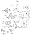
- FIG. 1 is a block diagram illustrating various aspects of the present invention, including an improved computing machine 100 that includes a pipelined processor having the following functional circuits.
- a Fetch Controller (FECTL) 101 operates to control a fetch multiplexer/selector 102 and a onboard cache in a manner described in more detail below.
- This circuitry is involved in the first stage of the processor pipeline, which is responsible generally for fetching (and pre-fetching) instructions to ensure adequate instruction flow throughout the pipeline.
- an address for an instruction to be fetched is stored in a Fetch Instruction Address (FAL) latch 103; this is loaded in accordance with an output from a fetch mux 102 as explained below.
- FAL Fetch Instruction Address
- HB hint bit buffer
- HB includes three distinct control registers: (1) an instruction validity register configured so that each bit indicates a validity of a corresponding entry in an target instruction register set (see below); (2) a pre-load "mask” register, where each bit identifies the status of a hint/prediction bit for a corresponding one of the instruction address registers (see below); and (3) a select "mask” register, which indicates which of the target instruction registers is available for pre-loading.
- An instruction hint bit refers to a prediction, generated in advance by the compiler (or software program at run time) concerning whether a particular instruction is likely to be an actual target of a branch instruction when the latter is executed. Of course, other variations are possible, and may be more preferable for some applications of the present inventions.
- Fetch Instruction Address latch (FAL) 103 are retrieved from an Instruction Cache (IC) and cache controller, generally designated IC 105, during a first phase (F1) of the first stage in the pipeline using control line 106.
- IC 105 can store a plurality of 32-bit width program instructions that can be executed by processor 100.
- the capacity of IC 105 is 32KB, and a cache line size is 32B.
- Such cache can be constructed, for example, as a 4 way set associative cache memory using structures, methods and techniques that are well known in this field. Other approaches may be more desirable depending on the intended performance and hardware characteristics of processor 100.
- a conventional memory access cycle using a bus interface unit (not shown) must be run to retrieve the needed instruction.
- IC 105 would then be updated in a conventional fashion as well.
- IB 110 is Instruction Buffer 110, which stores a plurality of sequential program instructions.
- IB 110 is loaded with two instructions each cycle from IC 105, and includes capacity for four separate entries (4 instructions of 32 bits each, generally identified as ib0, ib1, ib2, ib3 (not shown here)).
- This structure is loaded during the second phase (F2) of the first stage of a pipeline of processor 100.
- F2 the second phase
- the maximum latency associated with this stage is 2 cycles.
- this approach for IB 110 is a compromise between an extremely deep and extremely shallow buffer, and the benefits of the present invention can be realized even if the specific implementation is varied slightly from environment to environment.
- IART Instruction Address Register Target
- IART 115 stores target instructions that have been pre-loaded so that they are ready to be executed as the destination of branch instructions, as explained in further detail below.
- IART has 8 entries, with each entry storing 2 instructions.
- a multiplexer/selector circuit (MUX_D) 118 is a selector that, depending on various parameters described below (including whether a branch instruction has been previously decoded) couples an instruction output from either IB 110 (input A) or IART 115 (input B) and routes it to a Decode Instruction Buffer (D) 120. This buffer is also loaded during the second phase (F2) of the first stage of the pipeline. The instruction stored here in this latch corresponds to a program instruction that is in a subsequent "decoding stage" of the microprocessor pipeline.
- the operating logic for MUX_D 118 is as follows: If (branch instruction) Select input A Else Select input B
- PC-D 128b contains an entry for the program counter (PC) corresponding to the instruction stored in the Decode Instruction Buffer (D) 120.
- PC-D 128b increments by an amount of 4 at incrementer 128 (since each instruction is 4 bytes wide) when a valid instruction path is flowing through the pipeline.
- the correct target address for such branch instruction is also set in PC-D 128b through input A to MUX_PC 128a, so that the correct target instruction will also be loaded within Decode Instruction Buffer 120.
- DEC 125 uses a Decode Unit (DEC) 125, for performing both a pre-decoding and decoding operation during a second pipeline stage.
- DEC 125 generates a number of control signals based on the type of instruction that is predecoded/decoded, and these signals (described below) are passed on by way of control signal bus 129.
- a pre-decode operation is performed very rapidly when the instruction is loaded, to determine if it is a branch instruction. In this way, the branch control handling can be executed very quickly in turn.
- This pre-decode operation can be implemented with any of a variety of standard techniques commonly employed in the art for quickly identifying particular instruction types. As illustrated in FIG.
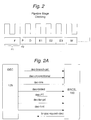
- the pre-decode operation (P) in fact, takes place during (overlaps) the first stage of the pipeline's operation (during the second phase F2 of the F stage) and prior to the second decoding stage (D) to ensure proper timing for the remainder of the branch control circuitry.
- the decoded instruction output from DEC 125 passes to two (2) E1 Operand Buffers (E1) 127a and 127b, respectively for storing operands for program instructions that are being processed in an execution stage (E1 stage in FIG.2) performed by Arithmetic Logic Unit (ALU) 130 as part of a third pipeline stage.
- E1 stage in FIG.2 the execution stage
- ALU Arithmetic Logic Unit
- Data Cache Connected to an output of ALU 130 are a set of General Purpose Registers (GPR) 135, and a load/store address register 138 for storing an address used for a load/store operation with Data Cache 140 as part of a later pipeline stage. These circuits are updated during a W stage shown in FIG. 2.
- GPR General Purpose Registers
- Data Cache includes a 4-way, 32 Byte line associated cache, such that the entire capacity is 32KB.
- An Instruction Address Register set for Addresses of branch targets (IAR.A) 140 stores target addresses for branch instructions as they are computed by ALU 130 and loaded during the W stage. Each of the entries in IARA 140 has a related corresponding entry in IART 110 above. As noted above, by using a branch control (PT) instruction, the target addresses can be prepared in advance, and stored as a 32 bit entity in one of eight (8) entries.
- the output of IAR.A 140 and ALU 130 are both fed to a branch selector/mux 146, which selects one such input based on a control signal provided by Branch Control circuit 150 (BRCTL) on branch control line 151.
- BRCTL Branch Control circuit 150
- BRCTL 150 is generally responsible for executing any branch instructions, as described below. This circuit receives the decoded branch and branch control instructions, determines whether branch condition and target addresses are known, and resolves/predicts the outcome of the branch. If the branch condition is unknown, BRCTL 150 predicts the branch conditionally based on a branch hint bit (BHB) (discussed below) within the branch instruction. At this point, the target address should already be known (as explained below) because of the branch control (PT) instruction. In a number of cases, branch latency can be effectively eliminated if the prediction is correct.
- BHB branch hint bit
- branch control signals generated by BRCTL 150 are also described in more detail below, and in the accompanying figures, which including comprehensive timing diagrams. As the architecture and timing requirements of such circuit are easily gleaned with reference to the present disclosure, and such can be implemented by a variety of suitably configured and connected hardware logic, memory and clocking circuits known in the art, such circuits are not discussed at length herein.
- a Target Instruction Address Register Incremented Address buffer (IAR.IA) 155 stores entries containing incremented target addresses, if the corresponding instruction stored in IART 115 represents a valid target instruction for a branch. In this embodiment, 8 separate entries are provided for IAR.IA 155. This circuit is loaded by reading and incrementing fetch addresses (by +4 or +8) output by Fetch Instruction Latch 103, when such correspond to target instruction addresses for branch instructions.
- control signals shown generally in FIG. 2A, are generated by DEC 125 on decode control line 129 during the pre-decode stage (see FIG. 2) as inputs for use within BRCTL 150:
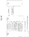
- control signals shown generally in FIG. 2B, are generated by BRCTL 150 on branch control line 152 as inputs for use within FECTL 101:
- BRCTL 150 also generates a "squash” - br_ppc_squash_dec and br_ppc_squash_E1, which are used by a pipeline control unit (not shown) to remove instructions from DEC 125 and ALU 130 when they are no longer valid. This type of instruction squashing operation is well-known in the art, and therefore any conventional implementation compatible with the present invention can be used. BRCTL 150 also receives the branch false signal referred to above, which is identified more specifically in other places in the figures as imu_fcmp_pred_ex1.
- control signals are generated by FECTL 101 on branch control lines 152 as inputs for use within BRCTL 150:
- MUX_BR 146 is a selector for a target address. MUX_BR 146 is controlled by a selector signal output on branch address control line 151 by BRCTL 150, which indicates whether there is an outstanding PT instruction.
- the control logic for this selector is as follows: If (outstanding PT instruction) Select Input A Else Select Input B
- MUX_FE 102 is a selector for a fetch address. MUX_FE 102 is controlled by selector signals from FECTL 101 (indicating whether there is a branch instruction, and whether the IAR.IA entry is valid) on control line 106. The control logic for this selector is as follows: If (branch instruction) If (IAR.IA entry is valid) Select Input A Else Select Input B Else Select Input C
- a fetch address is stored in Instruction Fetch Address latch (IFAL) 103 as discussed earlier.
- IFAL Instruction Fetch Address latch
- icc_fe_command an additional set of fetch command signals, illustrated generally as icc_fe_command in FIG. 2B, are generated by FECTL 101 and sent along as well on line 106 to control the cache access. This includes the following control information:
- processor 100 including the other various inventive aspects of the present invention, can be gleaned with reference to the FIG. 1A, and the examples that follow.
- the overall process employed in the present invention includes the following basic steps: a branch operation is detected first at step 180; in this case, the branch-control (PT) instruction in fact signals this upcoming operation to computing system 100. Then, based on compiler/software analysis, a prediction is made at step 182 concerning whether the branch instruction is likely to be taken or not taken (by setting the hint bit noted earlier).
- branch target address information is prepared at step 184, based on information provided in the PT instruction. As explained below, this information may already be available prior to detecting the branch, due to preloading operations.
- computing system 100 sets up the pipeline to pre-load the appropriate target address registers and target instruction registers at step 186.
- the branch condition is then resolved at step 188, to determine if the branch is actually taken or not-taken. Based on this determination, at step 190 the computing system then determines whether any necessary adjustments need to be made to the pipeline because of a mis-prediction.
- instruction flow is appropriately directed to the correct instruction sequence, based on the fact that any necessary target instructions for a correctly predicten branch will now available for execution. While the aforementioned steps are shown in a particular sequence, it is not necessarily the case that they must be executed in such manner, and the present invention is not limited to any particular arrangement or timing of such steps.
- the branch detection operation (at step 180) is performed within decoding unit DEC 125, but it is usually the case that every branch operation is already predicted (step 182) by that time. Furthermore, as is apparent from the discussions herein, many of these steps take place at the same time, or overlap significantly from a temporal perspective. Thus, it will be understood by those skilled in the art that the above is a simplified explanation of the detailed operation that is described herein and in the accompanying figures, and that it is not intended to portray any required and/or fixed relationship between the various processes employed in the present invention.
- Non branch instruction (Ordinary instruction such as an addition instruction):
- a fetch address is set in FAL 103.
- IC 105 is accessed based on the fetch address, and the read out data is sent to IB 110.
- Two sequential instructions can be sent at once since instruction bus 107 is 64 bits in width.
- IB 110 is read (from the top) and an instruction is then stored in decode buffer 120, also during stage F2.
- IB 110 and D 120 are connected via MUX_D 118 since the previous instruction is not a branch instruction.
- an addition instruction in D is decoded by DEC 125 during a decode (D) stage.
- Any necessary data items are also read out from GPR 135 during the D stage and set in E1 latches 127a and 127b as operands for the addition instruction.
- the operand(s) in E1 127a and 127b are then acted upon byALU 130 during an E1 stage to effectuate an addition operation thereon.
- the result of this calculation is then stored in GPR 135 during a write (W) stage.
- W write
- FIG.1 While not shown explicitly in FIG.1, it is implicit that there are additional pipeline stages (e.g., E2 and E3) within the circuit designated 130, and they are referenced below where necessary to an explanation of the present disclosure. The particulars of the same are omitted here, however, since they are not crucial to an understanding of the present inventions.
- DEC 125 when a branch control (PT) instruction is decoded by DEC 125, any necessary data must be read out from GPR 135, or PC_D 128b (because of the flexible nature of the PT instruction, i.e., that displacements from the PC or register set can be used in computing target addresses) and set in El latch 127b as an operand.
- DEC 125 generates a series of control signals on line 129 to BRCTL, including dec_pt (indicating a decode of a PT instruction), as well as information for the additional parameters associated with the PT instruction, including dec_iar_pd and dec_hint.
- BRCTL 150 invalidates any instruction entry in IART 115 that exists having a target address stored in IARA 140 and pointed to by br_fe_pt_iar. This is done by setting the first (valid) bit in the instruction validity register to zero for such target instruction in HB 104. In addition, the br_fe_pt_hint information is used to set the second (hint) bit in HB 104 for the target instruction.
- the new target address is available for use in preloading, discussed further below.
- the results of ALU 130 including the calculation of the new target address, are stored in the IAR.A 140 entry designated by br_fe_pt_iar.
- FECTL 101 performs a number of important functions in the present invention, including preloading of branch target instructions and fetching of predicted branch target instructions. The latter function is discussed in more detail below in connection with conditional branches, but generally refers to the process of loading instructions from the instruction cache so as to maintain normal program flow, either from sequential execution (fetching instructions to be loaded into IB 110) or branch execution (searching IART 115, and if no target instructions are found, fetching instructions to be loaded).
- Pre-loading refers to a process whereby instructions are identified, retrieved and put into the pipeline ahead of time (i.e., before they are needed) by FECTL 101 during otherwise idle cache periods to ensure a continuous, uninterrupted stream of instructions.
- both active and passive preloading processes are used.
- active preload refers generally to the fact that FECTL speculatively requests instructions from IC 105 based on predicted branch conditions (i.e., taken or not taken). In other words, active preloading attempts to load IART 115 with instructions before the occurrence of the branch instruction.
- the active preloading procedure of the present invention is fairly sophisticated, and is explained in detail below.
- active preload is not synchronized with execution of instructions in the present preferred embodiment, but it is apparent nonetheless that it could be done this way in other applications of the invention.
- FECTL 101 preferably generates a preload request to IC 105 if it is viable to do so (i.e., BRCTL does not require some other operation, such as an instruction fetch for a branch) and when there are sufficient instructions in IB 110 to keep the pipeline full.
- a pre-load is not performed unless there are at least two available instructions in IB 110 ready for decoding; this is a compromise to ensure that the pipeline does not stall from an over-abundance of preload requests interfering with normal instruction fetches.
- a single entry is still preferably chosen, based on a loading priority within HB 104; for example, a simple approach is to use the entry with the smallest index number. Therefore, the select mask register is consulted, and the lowest rank IAR available is selected. After this IAR entry is selected for preload, the corresponding bit in the select mask register is cleared to ensure that there are not subsequent attempts to pre-load this entry again. Because of the limited idle time available for pre-fetching operations, it can seen that, under some circumstances, lower ranked IARs (such as IAR6 or IAR7) may never be reached for an active preload request.
- IAR entries can now be specified at the instruction level (as part of the branch control (PT) instruction), the active pre-loading behavior of the microarchitecture of computing system 100 can be controlled at the code level.
- the compiler can actively rank and prioritize preloading by specifing IARs of different rankings for such instructions.
- a branch control (PT) instruction for a likely branch could specify a low rank IAR, while unlikely branch could be provided with a high rank IAR.
- This prioritization approach has a number of advantages over other schemes, such as FIFO and LIFO. In the former case, no prioritization is possible, as all IARs are given equal opportunity, so there is no ability to influence or control pre-loading behavior.
- the lowest-to-highest ranking methodology is used for pre-loading, with the select mask register indicating which IARs remain available at any instant in time.
- the present approach further incorporates BRCTL 150 in the decision making process for a preload request as well, since the inventors have found that this results in more optimal feeding of instructions to the pipeline stages of processor 100.
- FECTL 101 detects such an available entry for preloading, it asserts fe_br_preload_req on line 152 to initiate a preload request, and also informs BRCTL 150 of the entry number with the preload control data specified in fe_br_preload_iar.
- BRCTL 150 receives fe_br_preload_iar, it reads out a target address from the designated entry of IAR.A based on such signal.
- a pre-load command PRLD
- BRCTL 150 by way of the br_fe_br_command (referred to earlier) and asserted on line 152 to FECTL 101.
- the read out target address is presented at the input of MUX_BR 146.
- the register number designated by fe_br_preload_iar is sent via signal br_fe_br_iarnum [2:0] from BRCTL 150 for storage/entry control of IAR.IA 155.
- FECTL 101 receives the PRLD command embodied in br_fe_br_command, and there is no need to fill IB 110 with more instructions (i.e., when more than two instructions are stored in IB 110) FECTL 101 then begins to execute the preload. That is, FECTL 101 controls MUX_BR 146 to select the target address from IAR.A 140 on line B, and then sets this address in FAL 103 by controlling MUX_FE 102 to select input B presented there.
- signal cache_no_fill is also asserted within the icc_ fe_command by FECTL 101 to IC 105 to prohibit unnecessary accesses to a main memory system (not shown) used by the processor.
- a valid instruction corresponding to the target address is located in IC 105, it is sent by instruction line 107 to be stored in IART 115.
- the contents of FAL are incremented by adder 157 by +4 or +8 (depending on the number of instructions fetched from IC 105) and an entry is then stored in IAR.IA 155.
- the purpose of this latter step is so that additional target instructions can be quickly preloaded during later execution of any branch instruction that uses the instructions in IART 115.
- the above mentioned preload operation is executed anytime after the E2 stage of a corresponding branch control (PT) instruction. If the execution of the PT instruction is not completely finished and the target address is not yet stored in IARA 140, BRCTL 150 detects that there is a PT instruction being executed, and accordingly controls MUX_BR 146 to send the calculation result of ALU 130 (input A) directly as a target address. It will be apparent to those skilled in the art that the determinations made by FECTL 101 in determining when to preload instructions may also be used to prefetch target instructions (i.e., if they are not available in an instruction cache, they must be fetched from main memory) if desired.
- target instructions i.e., if they are not available in an instruction cache, they must be fetched from main memory
- Branch type unconditional or conditional
- Prediction i.e., whether it is expected to be taken or not-taken
- Actual Branch direction i.e., whether it was actually taken or not-taken
- target instruction register conditions i.e., IART having 2 instructions, 1 instruction, 0 instructions, and IAR.A not being ready.
- a fetch address is already set in FAL 103.
- IC 105 is then accessed based on this address during the F1 and F2 stages, and the instructions are sent to IB 110.
- the contents of IB 110 read out (from the top of the buffer) and stored in latch D 120.
- next instruction to be executed does not immediately follow the unconditional branch instruction in the program sequence, it can still be executed that way by virtue of the fact that it has already been pre-loaded based on the decoding/execution of the branch control (PT) instruction above, which, as noted, sets up the appropriate target addresses, target instructions, etc., so that they are immediately ready when the branch instruction is decoded in the pipeline.
- PT branch control
- signal A TKN (branch actually taken) is sent by BRCTL 150 to FECTL 101 using the br_fe_br_command.
- the target address is read out from the entry in IAR.A designated by dec_iar_pd, and is presented as input B to MUX_BR 140.
- the IAR number holding the target address is also sent by br_fe_br_iarnum from BRCTL 150 to FECTL 101.
- FECTL 101 receives the ATKN signal, it then checks the validity of the IART entry pointed to by br_fe_br_iarnum by again checking the first (valid) bit of HB 104 corresponding to such IART entry.
- the pre-fetching operation looks to obtain the instruction immediately following the instruction already stored in IART 115 from IC 105.
- the address for this instruction has already been computed and stored in IAR.IA in the manner described above. Therefore, this next target address is read out from IARIA 155 (instead of IAR.A 140) and is asserted on input A of MUX_FE 102, and then selected by FECTL 101 so that it is sent to FAL 103 as the fetch address for IC 105.
- FECTL 101 accesses IC 105 based on this previously computed (incremented) target address.
- IB 110 is then loaded with the instructions in IC 105 pointed to by this target address.
- the appropriate target instructions are continuously provided in correct sequence to the pipeline, avoiding the conventional penalty cycles incurred in the prior art when a branch instruction is executed, such as from pipeline flushing, re-accessing the instruction cache to load new instructions, re-loading such instructions in the instruction buffer, etc.
- the target instruction, as well as the next instruction are loaded from IART 115, and any following instructions are then loaded from IC 105 to IB 110. It may be desirable, in some environments, to vary the size of IART 115, depending on available layout space, power requirements, etc. In general, however, to achieve good performance, this buffer need only be sufficiently deep (in this embodiment, two entries is sufficient) to offset any instruction cache latency.
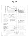
- FIG.3A A timing diagram illustrating the timing relationship between the aforementioned signals for the above scenario is provided in FIG.3A.
- MUX_D 1118 is controlled to select IB 110 on input B.
- FECTL 101 controls MUX_FE 102 so as to select the target address on input B coming from IAR.A 140.
- This target address sent from IAR.A is than loaded in FAL 103, and, as above, an access to IC 105 to locate the appropriate target instruction.
- the valid instruction from IC 105 is then sent and stored into both IB 110 and IART 115. According to this scheme, even if the branch instructions are not available the first time, at least when the same unconditional branch instruction is executed again, IART should probably store the correct target instruction. Therefore, when such instruction is encountered later, the procedure described in the paragraphs immediately above would be carried out, and a number of potential penalty cycles are again saved by virtue of the fact that the appropriate target instructions have now been preloaded.
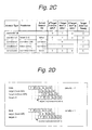
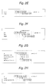
- FIGs. 2D to 2F provide visual snapshots of the state of the pipeline in computing system 100 for the three possible scenarios for unconditional branch instruction execution as it can occur therein. These include: (1) Unconditonal branch, where the target instruction is available in IART 115; (2) Unconditional branch, where the target instruction is not in IART 115; (3) Unconditional branch, where even the target address is not ready (as in the case, for example, where there is not adequate separation in time between a PT instruction and an associated branch instruction). For each case, an indication is given of the pipeline loading, and the maximum latency penalty associated with such branch execution.
- ALU 130 determines that the condition of the branch is false, and informs BRCTL 150 of this fact through signal imu_fcmp_pred_Ex1. BRCTL 150 then generates and asserts signal CNT (continue with predict taken failed) using br_fe_br command to FECTL 101 with a new target address. In this case, if the branch is not taken, the next instruction to be executed should be the one in IB 110 following the branch instruction sequentially in the program flow.
- the new target address is the program counter (PC) of the branch instruction +4 and this is loaded through input C of MUX_BR 146.
- PC program counter
- the information in some of the stages of the pipeline, including latch D 120 and E1 latch 127a are invalidated by BRCTL 150, since they contain instructions loaded from IART 115 which are now incorrect. This results in a small latency penalty because even though the branch is actually not taken, the pipeline still has the appropriate instructions available for processing. All that must be done is that the erroneously loaded instructions must be squashed (removed), and the pipeline must be re-filled with the correct instruction stream. Nonetheless, as the number of mis-predicted branches is expected to be small, this latency penalty is believed to be substantially outweighed by the performance advantages achieved by the overall branch handling architecture described herein.
- FECTL 101 When FECTL 101 receives the CNT signal, it then sends PC+4 to FAL 103 through MUX_D 102 where it is used, in the manner described earlier, to retrieve the appropriate target instruction so that the pipeline can be re-loaded.
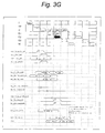
- a timing diagram illustrating the relationship between the relevant control signals for this scenario is provided in FIG.3G.
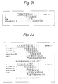
- FIGs. 2G to 2I provide visual snapshots of the state of the pipeline in computing system 100 for the three possible scenarios where a conditional branch instruction is mis-pre-dicted as taken, and it is in fact not-taken. These include: (1) conditonal branch with predict taken, actual not-taken, and where the target instruction is available in IART 115; (2) conditional branch with predict taken, actual not-taken, and where the target instruction is not in IART 115; (3) conditional branch with predict taken, actual not-taken, and where even the target address is not ready. For each case, an indication is given of the pipeline loading, and the maximum latency penalty associated with such branch execution.
- BRCTL 150 reads out target address pointed to in IAR.A 140, and sends the same to FECTL 101 on line B with a control signal PRLD (preload) in the br_fe_br_command. It also sends the IAR.A 140 entry number designated by the branch instruction using the br_fe_br_iarnum signal. If there are no conflicts with an instruction fetch for IB 110 fill, a preload request is sent to IC 105, and the operation then proceeds in the same manner as already described above for the active preload procedure.
- FIGs. 2J to 2L provide visual snapshots of the state of the pipeline in computing system 100 for the three possible scenarios where a conditional branch instruction is mis-pre-dicted as not-taken, and it is in fact taken. These include: (1) conditional branch with predict not taken, actual taken, and where the target instruction is available in IART 115; (2) conditional branch with predict not-taken, actual taken, and where the target instruction is not in IART 115; (3) conditional branch with predict not-taken, actual taken, and where even the target address is not ready. For each case, an indication is given of the pipeline loading, and the maximum latency penalty associated with such branch execution.
- the present invention uses additional attempts to correct even for mis-predictions of this type. This is because, as seen in FIG.2J, IART 115 may still have the branch instructions ready for execution, even if the branch is mis-predicted. Furthermore, even when IART 115 does not have such instructions, BRCTL 150 will still try to load them (even with a predict not-taken status for the branch) with the assistance of FECTL unless there is a higher priority fetch pending. Thus, significant potential latency cycles are avoided.
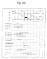
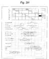
- Figs. 3A to 3G are timing diagrams illustrating the various signals used (and their relationship) during operation of the embodiments described herein, including during a branch instruction handling process. These diagrams particularly describe: (1) the state of the pipeline stages; (2) the progress of the instruction stream therein; (3) the identity and relative timing relationship of the control signals discussed above generated by DEC 125, BRCTL 150, FECTL 101, and other control logic, for a number of particular operational states that may arise within computing system 100.
- the potential states that are described include: (1) FIG. 3A - an unconditional branch instruction being handled when IART 115 is ready with target instructions; (2) FIG.
- FIG. 3B - a conditional branch, with a prediction (hint bit) indicating that the branch will be taken, and IART 115 is ready with target instructions when such branch is actually taken; (3) FIG. 3C - as for FIG. 3B, except IART 115 is not ready; (4) FIG. 3D - a conditional branch, with a prediction (hint bit) indicating that the branch will not be taken, such branch is actually not taken, but IART 115 is not ready with target instructions; (5) FIG. 3E - a conditional branch, with a prediction (hint bit) indicating that the branch will not be taken, IART 115 is ready with target instructions; but such branch is actually taken; (6) FIG.
- FIG. 3F same as 3E, except IART 115 is not ready; (7) FIG. 3G - same as FIG. 3D, except IART 115 is ready with target instructions.
- T0 - T7 refer to the IARs described above, and likewise ib0 refers to IB 110.
- FIG. 3H depicts how an improved branch control (PT) instruction is handled by computing system 100.
- PT branch control
- the microarchitecture described above is specifically designed to coordinate branch handlings using a separated format, whereby a branch control instruction sets up a pipeline in advance so that a later branch instruction can be quickly and efficiently executed.
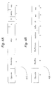
- the following portions of the disclosure are directed more particularly to a preferred embodiment of a structure for a branch control instruction and an associated branch instruction. These embodiments are depicted generally in FIGs. 4A and 4B respectively.
- branch control (PT) instruction is described herein as an entirely separate instruction from the actual branch instruction. While this instruction serves a number of purposes, one of the primary functions, from a simplified perspective, is to alert computing system that it should "prepare to branch" sometime soon in the instruction stream. Thus, while it performs some functions that are not commonly associated with a conventional branch instruction, it can, nonetheless, from an operational/functional perspective, be considered a logical component of the actual branch instruction, since the two are always logically and operationally linked.
- branch control (PT) instruction further improve flexibility and efficient utilization of the branch control logic used in computing system 100.
- the target address is calculated in advance, exception checks can be made before it is actually stored in one of the IARs in IAR.A 140.
- the target address can be checked to ensure it is within the implemented part of the address space, otherwise an exception can be raised.
- the target address can be checked to ensure that it is appropriately aligned for the target instruction, otherwise an exception can be raised.
- Other applications may require additional types of exceptions to be checked as well.
- branch control (PT) instruction can also include its own separate prediction bit; this parameter actually takes into account information quite distinct from that considered for a the branch instruction of the present invention discussed further below. The implications of this are quite significant, in that this adds a separate level of prediction that is believed to be unlike that in the prior art. This is due to the fact that, as seen above, the PT hint bit is typically used to speculatively predict/execute pre-fetch operations within computing system 100, and takes into account the cumulative probability of a number of potential branch operations that may require a particular branch target instruction.
- branch prediction hint This is quite different from the branch prediction hint, as the latter is only used to distinguish the later flow of the instruction stream (taken or not taken).
- a number of competing considerations can be taken into account. For instance, as will be explained below, it is possible that multiple branch instructions will be associated with a single PT instruction. Thus, the PT hint bit must factor the possibility that any one of these potential branches may implicate or require the target instruction. From a high level perspective, therefore, the PT hint essentially predicts whether a particular target instruction is likely to be needed in IART 115. In the applicant's experience, this cumulative accounting of branch probabilities provides a more accurate target instruction prediction process, and ensures that more appropriate instructions are loaded in advance and ready for execution when they are needed.
- FIG.4B A typical example of placement of the use of PT instructions in a conventional program is shown in FIG.4B, where two PT instructions are placed in front of two distinct loops (BEGIN_LOOP and INC). For the reasons set out above, these instructions are hoisted (placed) before their counterpart branch instructions. The most substantial gains are realized when PT instructions are hoisted out of inner loops, as seen in FIG. 4B.
- these branch control instructions are arranged so that there is maximum separation in the dynamic instrution stream from the branch instruction that reads the target address register. Again, this gives the branch mechanism the maximum amount of time to arrange for the flow of instructions to be changed or maintained without penalties.
- the placement of these instructions can be highly optimized using standard compiler techniques such as loop/block - invariant code motion, common sub-expression elimination, register allocation and instruction scheduling. Where more than PT instruction from more than one branch refers to the same target instruction, the PT instructions can be merged; and, as indicated above, the PT hint bit can be adjusted in accordance with an evaluation of the prediction scenario for the multiple branches to better reflect expected instruction flow conditions. From a practical perspective, the only limits on this optimization are based on the particular environment constraints, such as the size of the functions called, the number of address registers used, and any data/control dependencies in the program.
- branch instruction 420 further improve flexibility and efficient utilization of the branch control logic used in computing system 100.
- the now-available parameter fields can be used to effectuate an operation that can be described generaly as "compare-fold.” By this it is meant that a compare instruction commonly used in programs can now be folded (merged) into the branch instruction itself. This, of course, saves significant time by eliminating an entire instruction, and can reduce overall code size considerably.
- the Rm and Rn fields are used as operands (source1, source2) by the type of branch specified in the branch extension field to implement one of many different types of branch instructions, including: BEQ source1, source2, target Branch if equal (64 bit compare) BNE source1, source1, target Branch if not equal (64 bit compare) BGT source1 source1, target Branch if greater (64 bit signed) BGE source1, source2, target Branch if greater than or equal (64 bit signed) BGTU source1, source2, target Branch if greater than (64 bit unsigned) BGEU source1, source2, target Branch if greater than or equal (64 bit unsigned)
- conditional branches can be coded and executed in some applications based on operand (or register) predicate evaluations. In other words, a branch might be taken only if both predicates (Pm, Pn) (which can be register values) were evaluated logically true (or false), or if one or the other had a true condition, etc. Additional methods for constructing additional types of branch instructions that evaluate multiple predicate operands as part of a compare operation will be apparent to those skilled in the art from the present teachings.
- branch operations require a comparison of a branch parameter with zero. If register 63 is permanently assigned to have a zero value, such operations can be replaced by a single branch instruction with R63 set as one of the operands. This simplifies the formatting of the instructions significantly, and improves execution speed.
- Other types of branch instructions will be apparent to those in the art, and can be easily implemented based on the availability and variety of coding fields used for PT instruction 410.
- additional conditional branch instructions that can be implemented in the present invention include those that compare register values with a constant that is not specified in a register.
- conditional branch instructions of the present invention are arranged in sequences throughout the code so that they favor fall-through (i.e., non-redirect of instruction flow) to avoid branch penalties.
- a conditional branch instruction 420 includes a prediction bit (L). This bit helps computing system 100 determine whether it should begin execution of the predicted path, even before the branch condition is resolved.
- Various well-known techniques can be used for setting this bit, based on analyzing standard compiler heuristics, or branch profile information.
- one or more target instructions can be pre-loaded into IART 115 in advance of execution of the program, to enhance branch speed, and improve overall program performance. This can be done by various techniques, including by code scanning (to identify branch instructions) or by explicit register loading through a configuration instruction that can identify and store branch target addresses, target instructions, etc. directly in IAR.T 115 and/or IAR.A 140 prior to executing some portion of the program, such as a loop.
- a configuration instruction may be executed which sets up the architecture of computing machine 100 (including with prospective branch target addresses) so as to be primed for execution of one or more code portions.
- the determination of which branch addresses/instructions to load can be based on any number of considerations by a skilled program designer, and because of varying system characterististics, it is expected that the precise methodology will vary from application to application.
- An unconditional branch instruction 430 has a slightly different format, as seen in Fig. 4D, and can be considered as a branch and link (BLINK) instruction having a format BLINK Target, Link.
- BLINK branch and link
- BLINK writes the target address of the subsequent instruction to a destination register Rd in GPR 135. Since it allows the target instruction sequence to return control back to the instruction sequence that invoked it, this can be considered a linking mechanism. Thus, it can be used to implement standard call and return mechanisms.
- a special register can be dedicated in GPR 135, so that a branch instruction formatted as: BLINK Target, R63 will transfer control the target without writing to a destination register.
- branch control/branch instructions many different types of variations and combinations of the branch control/branch instructions are possible.
- structure/format of such instructions would need to be adjusted slightly to best fit the particular microarchitecture employed. Nonetheless, if such applications utilize the principles and features discussed above, it is expected that they will also benefit significantly from a branch operation performance perspective.
- computing system 100 may, in some instances, be used to support two separate instruction sets, which, for ease of illustration, can be thought of as Set A and Set B.
- the processor executes in two separate modes of operation (i.e, Mode A and Mode B).
- Mode A and Mode B The use of more than one instruction set is helpful in some applications to support programming optimizations (i.e., such as in cases where it is determined that program performance is substantially superior in one mode or the other) or where it might be desirable to support legacy software (i.e., programs containing only more primitive instructions).
- computing system 100 is optimized to execute Mode A instructions, which, as noted below, are 32 bit instructions, but, for the above reasons, it is also capable of supporting instruction Set B as well, which consists of 16 bit instructions.
- Mode A operation is optimized from the perspective that the overall architecture, timing, bus protocols, data paths, specific circuit implementations, etc., are built around supporting the instructions in Set A.
- To execute the Set B instructions it is preferable to emulate them using the other Set A instructions, so that hardware and programming complexity are reduced.
- the present computing system 100 makes no distinction concerning its status as an instruction from set A or set B. This differentiation is made, for example, by Decoder 125 during a decoding or pre-decoding operation.
- Decoder 125 When an instruction from set B is encountered, it can be directed to separate pipeline stage (not shown) and converted (using any of a number of conventional techniques) to one or more set A instructions. These set A replacement instructions are then inserted into the appropriate stage of the pipeline for execution in the normal manner as any other set A instructions.
- At least the Mode A operation of the computing system 100 should use a separated branch process as described above; i.e., a branch instruction coupled with a branch control instruction presented earlier in the program flow that is used to calculate a target address in advance, set up buffers and logic within system 100, and also includes a folded branch condition/direction format for the branch instruction itself (as seen in Fig. 3B).
- instruction set B does not use a separate branch control instruction for computing the target address, and uses a separate compare instruction to resolve the branch condition. Furthermore, a branching process used in this Mode B operation adds a delayed branch instruction that results in executing the instruction following the branch unconditionally.
- the present invention thus emulates a mode B branch instruction by a mode A branch control (PT) instruction, followed by a mode A branch instruction.
- PT mode A branch control
- a back-to-back PT and branch instruction will result in a pipeline bubble, there is inevitably a 1 cycle penalty for mode B branches.
- support for mode B support operation is not expected to be great in most applications, this is in fact a very acceptable result in practice.
- the branch control instruction in this instance is generated by DEC 125 (and not by compiler/software determinations), and therefore the associated hint bit cannot be generated reliably. It is conceivable, however, that the hint bit could be adjusted by additional monitoring logic (not shown) in some environments (based on the path taken by the branch instruction) to similarly imitate the behavior of the compiler determinations made for the mode A instruction based programs.
- the fall-through instruction in Mode A is executed unconditionally.
- BRCTL 150 holds on to the branch target address until FECTL 101 can accept it for initiating a new instruction fetch. This is because a mode B delay-slot instruction may be on a different cache line in IC 105, so it is not necessarily loaded in the correct time location in IB 110. Normally, BRCTL 150 determines the branch direction, and then re-directs the fetch path without waiting. In the case of a delayed branch, however, if the delay slot instruction has missed the cache access, direction of the program flow cannot be changed until it has been fetched.
Landscapes
- Engineering & Computer Science (AREA)
- Software Systems (AREA)
- Theoretical Computer Science (AREA)
- Physics & Mathematics (AREA)
- General Engineering & Computer Science (AREA)
- General Physics & Mathematics (AREA)
- Advance Control (AREA)
- Executing Machine-Instructions (AREA)
Applications Claiming Priority (2)
| Application Number | Priority Date | Filing Date | Title |
|---|---|---|---|
| US410682 | 1989-09-21 | ||
| US09/410,682 US6772325B1 (en) | 1999-10-01 | 1999-10-01 | Processor architecture and operation for exploiting improved branch control instruction |
Publications (2)
| Publication Number | Publication Date |
|---|---|
| EP1089170A2 true EP1089170A2 (de) | 2001-04-04 |
| EP1089170A3 EP1089170A3 (de) | 2004-02-04 |
Family
ID=23625778
Family Applications (1)
| Application Number | Title | Priority Date | Filing Date |
|---|---|---|---|
| EP00308562A Withdrawn EP1089170A3 (de) | 1999-10-01 | 2000-09-29 | Prozessorarchitektur und Verfahren zum Verarbeiten von Verzweigungssteuerungsbefehlen |
Country Status (5)
| Country | Link |
|---|---|
| US (2) | US6772325B1 (de) |
| EP (1) | EP1089170A3 (de) |
| JP (1) | JP2001147807A (de) |
| KR (1) | KR20010050794A (de) |
| TW (1) | TW523711B (de) |
Cited By (5)
| Publication number | Priority date | Publication date | Assignee | Title |
|---|---|---|---|---|
| EP1267255A3 (de) * | 2001-06-11 | 2003-05-02 | Broadcom Corporation | Ausführung bedingter Verzweigungen in einem Mehrfachdatenpfadprozessor |
| US7127593B2 (en) | 2001-06-11 | 2006-10-24 | Broadcom Corporation | Conditional execution with multiple destination stores |
| US7287152B2 (en) | 2001-06-11 | 2007-10-23 | Broadcom Corporation | Conditional execution per lane |
| CN102144232A (zh) * | 2008-09-04 | 2011-08-03 | 爱立信电话股份有限公司 | 使用分支取代的仿真处理器执行 |
| CN111433740A (zh) * | 2018-01-03 | 2020-07-17 | Arm有限公司 | 推测屏障指令 |
Families Citing this family (71)
| Publication number | Priority date | Publication date | Assignee | Title |
|---|---|---|---|---|
| US7171547B1 (en) * | 1999-12-28 | 2007-01-30 | Intel Corporation | Method and apparatus to save processor architectural state for later process resumption |
| US6904057B2 (en) * | 2001-05-04 | 2005-06-07 | Slt Logic Llc | Method and apparatus for providing multi-protocol, multi-stage, real-time frame classification |
| US6901052B2 (en) | 2001-05-04 | 2005-05-31 | Slt Logic Llc | System and method for policing multiple data flows and multi-protocol data flows |
| US6944168B2 (en) * | 2001-05-04 | 2005-09-13 | Slt Logic Llc | System and method for providing transformation of multi-protocol packets in a data stream |
| US20030204705A1 (en) * | 2002-04-30 | 2003-10-30 | Oldfield William H. | Prediction of branch instructions in a data processing apparatus |
| US8719837B2 (en) | 2004-05-19 | 2014-05-06 | Synopsys, Inc. | Microprocessor architecture having extendible logic |
| US7861063B1 (en) * | 2004-06-30 | 2010-12-28 | Oracle America, Inc. | Delay slot handling in a processor |
| US7647487B2 (en) * | 2005-08-29 | 2010-01-12 | Searete, Llc | Instruction-associated processor resource optimization |
| US7739524B2 (en) * | 2005-08-29 | 2010-06-15 | The Invention Science Fund I, Inc | Power consumption management |
| US8214191B2 (en) * | 2005-08-29 | 2012-07-03 | The Invention Science Fund I, Llc | Cross-architecture execution optimization |
| US20070050604A1 (en) * | 2005-08-29 | 2007-03-01 | Searete Llc, A Limited Liability Corporation Of The State Of Delaware | Fetch rerouting in response to an execution-based optimization profile |
| US7779213B2 (en) | 2005-08-29 | 2010-08-17 | The Invention Science Fund I, Inc | Optimization of instruction group execution through hardware resource management policies |
| US8423824B2 (en) | 2005-08-29 | 2013-04-16 | The Invention Science Fund I, Llc | Power sparing synchronous apparatus |
| US8255745B2 (en) | 2005-08-29 | 2012-08-28 | The Invention Science Fund I, Llc | Hardware-error tolerant computing |
| US7539852B2 (en) | 2005-08-29 | 2009-05-26 | Searete, Llc | Processor resource management |
| US8209524B2 (en) * | 2005-08-29 | 2012-06-26 | The Invention Science Fund I, Llc | Cross-architecture optimization |
| US7512842B2 (en) * | 2005-08-29 | 2009-03-31 | Searete Llc | Multi-voltage synchronous systems |
| US7725693B2 (en) * | 2005-08-29 | 2010-05-25 | Searete, Llc | Execution optimization using a processor resource management policy saved in an association with an instruction group |
| US8181004B2 (en) | 2005-08-29 | 2012-05-15 | The Invention Science Fund I, Llc | Selecting a resource management policy for a resource available to a processor |
| US7493516B2 (en) * | 2005-08-29 | 2009-02-17 | Searete Llc | Hardware-error tolerant computing |
| US8516300B2 (en) | 2005-08-29 | 2013-08-20 | The Invention Science Fund I, Llc | Multi-votage synchronous systems |
| US7877584B2 (en) * | 2005-08-29 | 2011-01-25 | The Invention Science Fund I, Llc | Predictive processor resource management |
| US7627739B2 (en) * | 2005-08-29 | 2009-12-01 | Searete, Llc | Optimization of a hardware resource shared by a multiprocessor |
| US20070073925A1 (en) | 2005-09-28 | 2007-03-29 | Arc International (Uk) Limited | Systems and methods for synchronizing multiple processing engines of a microprocessor |
| EP2011018B1 (de) | 2006-04-12 | 2016-07-13 | Soft Machines, Inc. | Vorrichtung und verfahren zur verarbeitung einer instruktionsmatrix zur definition paralleler und abhängiger operationen |
| US7958181B2 (en) * | 2006-09-21 | 2011-06-07 | Intel Corporation | Method and apparatus for performing logical compare operations |
| CN107368285B (zh) | 2006-11-14 | 2020-10-09 | 英特尔公司 | 多线程架构 |
| EP2106584A1 (de) * | 2006-12-11 | 2009-10-07 | Nxp B.V. | Pipeline-prozessor und compiler/planer für branch-delay-slots mit veränderlicher anzahl |
| EP1953959A1 (de) * | 2007-02-01 | 2008-08-06 | British Telecommunications Public Limited Company | Datenkommunikation |
| US8218003B2 (en) * | 2007-10-05 | 2012-07-10 | Seiko Epson Corporation | Optimization strategies for GPU view projection matrix implementation |
| KR101579589B1 (ko) * | 2009-02-12 | 2015-12-22 | 삼성전자 주식회사 | 파이프라인 프로세서를 위한 정적 분기 예측 방법과 이를 위한 컴파일 방법 |
| US8082467B2 (en) * | 2009-12-23 | 2011-12-20 | International Business Machines Corporation | Triggering workaround capabilities based on events active in a processor pipeline |
| US9104399B2 (en) * | 2009-12-23 | 2015-08-11 | International Business Machines Corporation | Dual issuing of complex instruction set instructions |
| US9135005B2 (en) * | 2010-01-28 | 2015-09-15 | International Business Machines Corporation | History and alignment based cracking for store multiple instructions for optimizing operand store compare penalties |
| US8495341B2 (en) * | 2010-02-17 | 2013-07-23 | International Business Machines Corporation | Instruction length based cracking for instruction of variable length storage operands |
| US8938605B2 (en) * | 2010-03-05 | 2015-01-20 | International Business Machines Corporation | Instruction cracking based on machine state |
| US8464030B2 (en) | 2010-04-09 | 2013-06-11 | International Business Machines Corporation | Instruction cracking and issue shortening based on instruction base fields, index fields, operand fields, and various other instruction text bits |
| US8645669B2 (en) | 2010-05-05 | 2014-02-04 | International Business Machines Corporation | Cracking destructively overlapping operands in variable length instructions |
| EP3156896B1 (de) | 2010-09-17 | 2020-04-08 | Soft Machines, Inc. | Mehrfach verzweigte einzelzyklusvorhersage mit einem latenten cache für frühe und entfernte verzweigungsvorhersage |
| CN108108188B (zh) | 2011-03-25 | 2022-06-28 | 英特尔公司 | 用于通过使用由可分区引擎实例化的虚拟核来支持代码块执行的存储器片段 |
| KR101620676B1 (ko) | 2011-03-25 | 2016-05-23 | 소프트 머신즈, 인크. | 분할가능한 엔진에 의해 인스턴스화된 가상 코어를 이용한 코드 블록의 실행을 지원하는 레지스터 파일 세그먼트 |
| CN103547993B (zh) | 2011-03-25 | 2018-06-26 | 英特尔公司 | 通过使用由可分割引擎实例化的虚拟核来执行指令序列代码块 |
| CN107729267B (zh) | 2011-05-20 | 2022-01-25 | 英特尔公司 | 资源的分散分配以及用于支持由多个引擎执行指令序列的互连结构 |
| US9442772B2 (en) | 2011-05-20 | 2016-09-13 | Soft Machines Inc. | Global and local interconnect structure comprising routing matrix to support the execution of instruction sequences by a plurality of engines |
| WO2013077876A1 (en) | 2011-11-22 | 2013-05-30 | Soft Machines, Inc. | A microprocessor accelerated code optimizer |
| KR101703401B1 (ko) * | 2011-11-22 | 2017-02-06 | 소프트 머신즈, 인크. | 다중 엔진 마이크로프로세서용 가속 코드 최적화기 |
| US20130159679A1 (en) * | 2011-12-20 | 2013-06-20 | James E. McCormick, Jr. | Providing Hint Register Storage For A Processor |
| US8806456B2 (en) * | 2012-05-31 | 2014-08-12 | New York University | Configuration-preserving preprocessor and configuration-preserving parser |
| US9135012B2 (en) * | 2012-06-14 | 2015-09-15 | International Business Machines Corporation | Instruction filtering |
| US9104532B2 (en) * | 2012-12-14 | 2015-08-11 | International Business Machines Corporation | Sequential location accesses in an active memory device |
| US10275255B2 (en) | 2013-03-15 | 2019-04-30 | Intel Corporation | Method for dependency broadcasting through a source organized source view data structure |
| US9891924B2 (en) | 2013-03-15 | 2018-02-13 | Intel Corporation | Method for implementing a reduced size register view data structure in a microprocessor |
| US9886279B2 (en) | 2013-03-15 | 2018-02-06 | Intel Corporation | Method for populating and instruction view data structure by using register template snapshots |
| US9904625B2 (en) | 2013-03-15 | 2018-02-27 | Intel Corporation | Methods, systems and apparatus for predicting the way of a set associative cache |
| US10140138B2 (en) | 2013-03-15 | 2018-11-27 | Intel Corporation | Methods, systems and apparatus for supporting wide and efficient front-end operation with guest-architecture emulation |
| WO2014150806A1 (en) | 2013-03-15 | 2014-09-25 | Soft Machines, Inc. | A method for populating register view data structure by using register template snapshots |
| WO2014151043A1 (en) | 2013-03-15 | 2014-09-25 | Soft Machines, Inc. | A method for emulating a guest centralized flag architecture by using a native distributed flag architecture |
| WO2014150971A1 (en) | 2013-03-15 | 2014-09-25 | Soft Machines, Inc. | A method for dependency broadcasting through a block organized source view data structure |
| EP2972845B1 (de) | 2013-03-15 | 2021-07-07 | Intel Corporation | Verfahren zur ausführung von in blöcken gruppierten befehlen aus mehreren threads |
| US9811342B2 (en) | 2013-03-15 | 2017-11-07 | Intel Corporation | Method for performing dual dispatch of blocks and half blocks |
| US9569216B2 (en) | 2013-03-15 | 2017-02-14 | Soft Machines, Inc. | Method for populating a source view data structure by using register template snapshots |
| WO2014150991A1 (en) | 2013-03-15 | 2014-09-25 | Soft Machines, Inc. | A method for implementing a reduced size register view data structure in a microprocessor |
| JP5863855B2 (ja) * | 2014-02-26 | 2016-02-17 | ファナック株式会社 | 分岐命令を高速に処理するためのインストラクションキャッシュを有するプログラマブルコントローラ |
| US9916185B2 (en) | 2014-03-18 | 2018-03-13 | International Business Machines Corporation | Managing processing associated with selected architectural facilities |
| US9582295B2 (en) | 2014-03-18 | 2017-02-28 | International Business Machines Corporation | Architectural mode configuration |
| US9588774B2 (en) | 2014-03-18 | 2017-03-07 | International Business Machines Corporation | Common boot sequence for control utility able to be initialized in multiple architectures |
| KR20160070965A (ko) | 2014-12-11 | 2016-06-21 | 삼성전자주식회사 | 컴파일러 |
| US9507598B1 (en) | 2015-12-15 | 2016-11-29 | International Business Machines Corporation | Auxiliary branch prediction with usefulness tracking |
| US11003454B2 (en) * | 2019-07-17 | 2021-05-11 | Arm Limited | Apparatus and method for speculative execution of instructions |
| KR102268112B1 (ko) * | 2019-12-24 | 2021-06-22 | 한국항공우주연구원 | 위성 커맨드 저장 처리 방법 및 위성 커맨드 저장 처리 시스템 |
| US12190114B2 (en) * | 2020-12-22 | 2025-01-07 | Intel Corporation | Segmented branch target buffer based on branch instruction type |
Citations (2)
| Publication number | Priority date | Publication date | Assignee | Title |
|---|---|---|---|---|
| EP0689131A1 (de) | 1994-06-22 | 1995-12-27 | STMicroelectronics Limited | Rechnersystem zur Ausführung von Verzweigungsbefehlen |
| US5857104A (en) | 1996-11-26 | 1999-01-05 | Hewlett-Packard Company | Synthetic dynamic branch prediction |
Family Cites Families (97)
| Publication number | Priority date | Publication date | Assignee | Title |
|---|---|---|---|---|
| US3573854A (en) * | 1968-12-04 | 1971-04-06 | Texas Instruments Inc | Look-ahead control for operation of program loops |
| JPS549456B2 (de) * | 1972-07-05 | 1979-04-24 | ||
| JPS5927935B2 (ja) * | 1980-02-29 | 1984-07-09 | 株式会社日立製作所 | 情報処理装置 |
| US4332010A (en) * | 1980-03-17 | 1982-05-25 | International Business Machines Corporation | Cache synonym detection and handling mechanism |
| US4400770A (en) * | 1980-11-10 | 1983-08-23 | International Business Machines Corporation | Cache synonym detection and handling means |
| US4704678A (en) * | 1982-11-26 | 1987-11-03 | Inmos Limited | Function set for a microcomputer |
| JPS6051948A (ja) * | 1983-08-31 | 1985-03-23 | Hitachi Ltd | 情報処理装置 |
| US4868742A (en) * | 1984-06-20 | 1989-09-19 | Convex Computer Corporation | Input/output bus for system which generates a new header parcel when an interrupted data block transfer between a computer and peripherals is resumed |
| US4873629A (en) * | 1984-06-20 | 1989-10-10 | Convex Computer Corporation | Instruction processing unit for computer |
| US4763245A (en) * | 1985-10-30 | 1988-08-09 | International Business Machines Corporation | Branch prediction mechanism in which a branch history table is updated using an operand sensitive branch table |
| US4935867A (en) * | 1986-03-04 | 1990-06-19 | Advanced Micro Devices, Inc. | Signal processor memory management unit with indirect addressing using selectable offsets and modulo values for indexed address calculations |
| US4797814A (en) * | 1986-05-01 | 1989-01-10 | International Business Machines Corporation | Variable address mode cache |
| JPS62293434A (ja) * | 1986-06-12 | 1987-12-21 | Nec Corp | 分岐先予測制御方式 |
| US4814981A (en) * | 1986-09-18 | 1989-03-21 | Digital Equipment Corporation | Cache invalidate protocol for digital data processing system |
| JPH0221342A (ja) * | 1987-02-27 | 1990-01-24 | Hitachi Ltd | マルチプロセッサシステム及びマルチプロセッサシステムにおける論理キャッシュメモリのアクセス方法 |
| US4926317A (en) * | 1987-07-24 | 1990-05-15 | Convex Computer Corporation | Hierarchical memory system with logical cache, physical cache, and address translation unit for generating a sequence of physical addresses |
| US5193205A (en) * | 1988-03-01 | 1993-03-09 | Mitsubishi Denki Kabushiki Kaisha | Pipeline processor, with return address stack storing only pre-return processed address for judging validity and correction of unprocessed address |
| JPH02157939A (ja) * | 1988-12-09 | 1990-06-18 | Toshiba Corp | 命令処理方法及び命令処理装置 |
| US5483518A (en) * | 1992-06-17 | 1996-01-09 | Texas Instruments Incorporated | Addressable shadow port and protocol for serial bus networks |
| JPH0666056B2 (ja) * | 1989-10-12 | 1994-08-24 | 甲府日本電気株式会社 | 情報処理システム |
| US5148538A (en) * | 1989-10-20 | 1992-09-15 | International Business Machines Corporation | Translation look ahead based cache access |
| JPH03217949A (ja) * | 1990-01-23 | 1991-09-25 | Hitachi Ltd | 計算機システム |
| US5163140A (en) * | 1990-02-26 | 1992-11-10 | Nexgen Microsystems | Two-level branch prediction cache |
| US5452432A (en) * | 1990-08-14 | 1995-09-19 | Chips And Technologies, Inc. | Partially resettable, segmented DMA counter |
| JP2984463B2 (ja) * | 1991-06-24 | 1999-11-29 | 株式会社日立製作所 | マイクロコンピュータ |
| US5423050A (en) * | 1991-11-27 | 1995-06-06 | Ncr Corporation | Intermodule test across system bus utilizing serial test bus |
| US5724549A (en) * | 1992-04-06 | 1998-03-03 | Cyrix Corporation | Cache coherency without bus master arbitration signals |
| GB2266606B (en) * | 1992-04-27 | 1996-02-14 | Intel Corp | A microprocessor with an external command mode |
| US5448576A (en) * | 1992-10-29 | 1995-09-05 | Bull Hn Information Systems Inc. | Boundary scan architecture extension |
| JP3524110B2 (ja) * | 1992-11-06 | 2004-05-10 | 株式会社ルネサステクノロジ | マイクロコンピュータシステム |
| JP3231429B2 (ja) * | 1992-11-06 | 2001-11-19 | 株式会社日立製作所 | 中央処理装置と乗算器とを有する半導体集積回路装置 |
| JPH06150023A (ja) * | 1992-11-06 | 1994-05-31 | Hitachi Ltd | マイクロコンピュータ及びマイクロコンピュータシステム |
| US5627842A (en) * | 1993-01-21 | 1997-05-06 | Digital Equipment Corporation | Architecture for system-wide standardized intra-module and inter-module fault testing |
| JP2731692B2 (ja) * | 1993-04-28 | 1998-03-25 | 日本電気アイシーマイコンシステム株式会社 | デバッグ装置 |
| DE4345028A1 (de) * | 1993-05-06 | 1994-11-10 | Hewlett Packard Co | Vorrichtung zur Reduzierung von Verzögerungen aufgrund von Verzweigungen |
| JP2596712B2 (ja) * | 1993-07-01 | 1997-04-02 | インターナショナル・ビジネス・マシーンズ・コーポレイション | 近接した分岐命令を含む命令の実行を管理するシステム及び方法 |
| US5598551A (en) * | 1993-07-16 | 1997-01-28 | Unisys Corporation | Cache invalidation sequence system utilizing odd and even invalidation queues with shorter invalidation cycles |
| EP0636976B1 (de) * | 1993-07-28 | 1998-12-30 | Koninklijke Philips Electronics N.V. | Mikrokontroller mit hardwaremässiger Fehlerbeseitigungsunterstützung nach dem Boundary-Scanverfahren |
| US5454117A (en) * | 1993-08-25 | 1995-09-26 | Nexgen, Inc. | Configurable branch prediction for a processor performing speculative execution |
| JP3904244B2 (ja) * | 1993-09-17 | 2007-04-11 | 株式会社ルネサステクノロジ | シングル・チップ・データ処理装置 |
| EP0652516A1 (de) | 1993-11-03 | 1995-05-10 | Advanced Micro Devices, Inc. | Integrierter Mikroprozessor |
| US5596734A (en) * | 1993-12-17 | 1997-01-21 | Intel Corporation | Method and apparatus for programming embedded memories of a variety of integrated circuits using the IEEE test access port |
| US5828825A (en) * | 1993-12-22 | 1998-10-27 | Intel Corporation | Method and apparatus for pseudo-direct access to embedded memories of a micro-controller integrated circuit via the IEEE test access port |
| US5434804A (en) * | 1993-12-29 | 1995-07-18 | Intel Corporation | Method and apparatus for synchronizing a JTAG test control signal to an on-chip clock signal |
| US5488688A (en) * | 1994-03-30 | 1996-01-30 | Motorola, Inc. | Data processor with real-time diagnostic capability |
| JPH07287668A (ja) * | 1994-04-19 | 1995-10-31 | Hitachi Ltd | データ処理装置 |
| JPH082819A (ja) | 1994-06-13 | 1996-01-09 | Murata Mach Ltd | 風綿回収装置のダストコレクター |
| GB9417602D0 (en) * | 1994-09-01 | 1994-10-19 | Inmos Ltd | A controller for implementing scan testing |
| JP3713312B2 (ja) * | 1994-09-09 | 2005-11-09 | 株式会社ルネサステクノロジ | データ処理装置 |
| US5907867A (en) * | 1994-09-09 | 1999-05-25 | Hitachi, Ltd. | Translation lookaside buffer supporting multiple page sizes |
| JP3740195B2 (ja) * | 1994-09-09 | 2006-02-01 | 株式会社ルネサステクノロジ | データ処理装置 |
| JP3672634B2 (ja) * | 1994-09-09 | 2005-07-20 | 株式会社ルネサステクノロジ | データ処理装置 |
| US5848247A (en) * | 1994-09-13 | 1998-12-08 | Hitachi, Ltd. | Microprocessor having PC card interface |
| US5664135A (en) * | 1994-09-28 | 1997-09-02 | Hewlett-Packard Company | Apparatus and method for reducing delays due to branches |
| US5613153A (en) * | 1994-10-03 | 1997-03-18 | International Business Machines Corporation | Coherency and synchronization mechanisms for I/O channel controllers in a data processing system |
| US5751621A (en) * | 1994-11-17 | 1998-05-12 | Hitachi, Ltd. | Multiply-add unit and data processing apparatus using it |
| TW330265B (en) * | 1994-11-22 | 1998-04-21 | Hitachi Ltd | Semiconductor apparatus |
| JP2752592B2 (ja) * | 1994-12-28 | 1998-05-18 | 日本ヒューレット・パッカード株式会社 | マイクロプロセッサ、マイクロプロセッサ−デバッグツール間信号伝送方法及びトレース方法 |
| US5778237A (en) * | 1995-01-10 | 1998-07-07 | Hitachi, Ltd. | Data processor and single-chip microcomputer with changing clock frequency and operating voltage |
| US5664197A (en) * | 1995-04-21 | 1997-09-02 | Intel Corporation | Method and apparatus for handling bus master channel and direct memory access (DMA) channel access requests at an I/O controller |
| US5867726A (en) * | 1995-05-02 | 1999-02-02 | Hitachi, Ltd. | Microcomputer |
| US5570375A (en) * | 1995-05-10 | 1996-10-29 | National Science Council Of R.O.C. | IEEE Std. 1149.1 boundary scan circuit capable of built-in self-testing |
| GB9509989D0 (en) * | 1995-05-17 | 1995-07-12 | Sgs Thomson Microelectronics | Manipulation of data |
| GB9509988D0 (en) * | 1995-05-17 | 1995-07-12 | Sgs Thomson Microelectronics | Matrix transposition |
| US5860127A (en) * | 1995-06-01 | 1999-01-12 | Hitachi, Ltd. | Cache memory employing dynamically controlled data array start timing and a microcomputer using the same |
| US5774701A (en) * | 1995-07-10 | 1998-06-30 | Hitachi, Ltd. | Microprocessor operating at high and low clok frequencies |
| GB9514684D0 (en) * | 1995-07-18 | 1995-09-13 | Sgs Thomson Microelectronics | An arithmetic unit |
| US5708773A (en) * | 1995-07-20 | 1998-01-13 | Unisys Corporation | JTAG interface system for communicating with compliant and non-compliant JTAG devices |
| US5737516A (en) * | 1995-08-30 | 1998-04-07 | Motorola, Inc. | Data processing system for performing a debug function and method therefor |
| US5704034A (en) * | 1995-08-30 | 1997-12-30 | Motorola, Inc. | Method and circuit for initializing a data processing system |
| JP3655403B2 (ja) * | 1995-10-09 | 2005-06-02 | 株式会社ルネサステクノロジ | データ処理装置 |
| JP3623840B2 (ja) * | 1996-01-31 | 2005-02-23 | 株式会社ルネサステクノロジ | データ処理装置及びマイクロプロセッサ |
| US5950012A (en) * | 1996-03-08 | 1999-09-07 | Texas Instruments Incorporated | Single chip microprocessor circuits, systems, and methods for self-loading patch micro-operation codes and patch microinstruction codes |
| US5978874A (en) * | 1996-07-01 | 1999-11-02 | Sun Microsystems, Inc. | Implementing snooping on a split-transaction computer system bus |
| TW334546B (en) * | 1996-03-18 | 1998-06-21 | Hitachi Ltd | Data processor |
| US5742804A (en) * | 1996-07-24 | 1998-04-21 | Institute For The Development Of Emerging Architectures, L.L.C. | Instruction prefetch mechanism utilizing a branch predict instruction |
| JP3579205B2 (ja) * | 1996-08-06 | 2004-10-20 | 株式会社ルネサステクノロジ | 半導体記憶装置、半導体装置、データ処理装置及びコンピュータシステム |
| GB9617033D0 (en) * | 1996-08-14 | 1996-09-25 | Int Computers Ltd | Diagnostic memory access |
| US5768152A (en) * | 1996-08-28 | 1998-06-16 | International Business Machines Corp. | Performance monitoring through JTAG 1149.1 interface |
| KR19980032776A (ko) * | 1996-10-16 | 1998-07-25 | 가나이 츠토무 | 데이타 프로세서 및 데이타 처리시스템 |
| JP3790307B2 (ja) * | 1996-10-16 | 2006-06-28 | 株式会社ルネサステクノロジ | データプロセッサ及びデータ処理システム |
| JP3641327B2 (ja) * | 1996-10-18 | 2005-04-20 | 株式会社ルネサステクノロジ | データプロセッサ及びデータ処理システム |
| GB9622686D0 (en) * | 1996-10-31 | 1997-01-08 | Sgs Thomson Microelectronics | A test port controller and a method of effecting communication using the same |
| US5983017A (en) * | 1996-11-12 | 1999-11-09 | Lsi Logic Corporation | Virtual monitor debugging method and apparatus |
| US5953538A (en) * | 1996-11-12 | 1999-09-14 | Digital Equipment Corporation | Method and apparatus providing DMA transfers between devices coupled to different host bus bridges |
| US5771240A (en) * | 1996-11-14 | 1998-06-23 | Hewlett-Packard Company | Test systems for obtaining a sample-on-the-fly event trace for an integrated circuit with an integrated debug trigger apparatus and an external pulse pin |
| US5956477A (en) * | 1996-11-25 | 1999-09-21 | Hewlett-Packard Company | Method for processing information in a microprocessor to facilitate debug and performance monitoring |
| US6119222A (en) * | 1996-12-23 | 2000-09-12 | Texas Instruments Incorporated | Combined branch prediction and cache prefetch in a microprocessor |
| US5896550A (en) * | 1997-04-03 | 1999-04-20 | Vlsi Technology, Inc. | Direct memory access controller with full read/write capability |
| US5978902A (en) * | 1997-04-08 | 1999-11-02 | Advanced Micro Devices, Inc. | Debug interface including operating system access of a serial/parallel debug port |
| US5944841A (en) * | 1997-04-15 | 1999-08-31 | Advanced Micro Devices, Inc. | Microprocessor with built-in instruction tracing capability |
| JPH1153188A (ja) * | 1997-07-30 | 1999-02-26 | Kobe Nippon Denki Software Kk | 命令キャッシュ制御方式 |
| US5974543A (en) * | 1998-01-23 | 1999-10-26 | International Business Machines Corporation | Apparatus and method for performing subroutine call and return operations |
| GB9802097D0 (en) | 1998-01-30 | 1998-03-25 | Sgs Thomson Microelectronics | DMA controller |
| GB9806184D0 (en) * | 1998-03-23 | 1998-05-20 | Sgs Thomson Microelectronics | A cache coherency mechanism |
| GB9809203D0 (en) * | 1998-04-29 | 1998-07-01 | Sgs Thomson Microelectronics | Packet distribution in a microcomputer |
| US6446197B1 (en) * | 1999-10-01 | 2002-09-03 | Hitachi, Ltd. | Two modes for executing branch instructions of different lengths and use of branch control instruction and register set loaded with target instructions |
-
1999
- 1999-10-01 US US09/410,682 patent/US6772325B1/en not_active Expired - Fee Related
-
2000
- 2000-09-13 JP JP2000278487A patent/JP2001147807A/ja active Pending
- 2000-09-29 EP EP00308562A patent/EP1089170A3/de not_active Withdrawn
- 2000-09-30 TW TW089120503A patent/TW523711B/zh not_active IP Right Cessation
- 2000-09-30 KR KR1020000057686A patent/KR20010050794A/ko not_active Withdrawn
-
2004
- 2004-06-15 US US10/869,760 patent/US7159102B2/en not_active Expired - Fee Related
Patent Citations (2)
| Publication number | Priority date | Publication date | Assignee | Title |
|---|---|---|---|---|
| EP0689131A1 (de) | 1994-06-22 | 1995-12-27 | STMicroelectronics Limited | Rechnersystem zur Ausführung von Verzweigungsbefehlen |
| US5857104A (en) | 1996-11-26 | 1999-01-05 | Hewlett-Packard Company | Synthetic dynamic branch prediction |
Non-Patent Citations (1)
| Title |
|---|
| H. C. YOUNG: "Code Scheduling Methods for Some Architectural Features in PIPE", MICROPROCESSING AND MICROPROGRAMMING, vol. 22, no. 1, 1988, pages 39 - 63 |
Cited By (7)
| Publication number | Priority date | Publication date | Assignee | Title |
|---|---|---|---|---|
| EP1267255A3 (de) * | 2001-06-11 | 2003-05-02 | Broadcom Corporation | Ausführung bedingter Verzweigungen in einem Mehrfachdatenpfadprozessor |
| US7127593B2 (en) | 2001-06-11 | 2006-10-24 | Broadcom Corporation | Conditional execution with multiple destination stores |
| US7287152B2 (en) | 2001-06-11 | 2007-10-23 | Broadcom Corporation | Conditional execution per lane |
| US7861071B2 (en) | 2001-06-11 | 2010-12-28 | Broadcom Corporation | Conditional branch instruction capable of testing a plurality of indicators in a predicate register |
| US8521997B2 (en) | 2001-06-11 | 2013-08-27 | Broadcom Corporation | Conditional execution with multiple destination stores |
| CN102144232A (zh) * | 2008-09-04 | 2011-08-03 | 爱立信电话股份有限公司 | 使用分支取代的仿真处理器执行 |
| CN111433740A (zh) * | 2018-01-03 | 2020-07-17 | Arm有限公司 | 推测屏障指令 |
Also Published As
| Publication number | Publication date |
|---|---|
| US7159102B2 (en) | 2007-01-02 |
| US20040225871A1 (en) | 2004-11-11 |
| JP2001147807A (ja) | 2001-05-29 |
| KR20010050794A (ko) | 2001-06-25 |
| EP1089170A3 (de) | 2004-02-04 |
| US6772325B1 (en) | 2004-08-03 |
| TW523711B (en) | 2003-03-11 |
Similar Documents
| Publication | Publication Date | Title |
|---|---|---|
| US7159102B2 (en) | Branch control memory | |
| US6477639B1 (en) | Branch instruction mechanism for processor | |
| US6324643B1 (en) | Branch prediction and target instruction control for processor | |
| US6523110B1 (en) | Decoupled fetch-execute engine with static branch prediction support | |
| US20110320787A1 (en) | Indirect Branch Hint | |
| US5553255A (en) | Data processor with programmable levels of speculative instruction fetching and method of operation | |
| US6029228A (en) | Data prefetching of a load target buffer for post-branch instructions based on past prediction accuracy's of branch predictions | |
| US6279105B1 (en) | Pipelined two-cycle branch target address cache | |
| US6381692B1 (en) | Pipelined asynchronous processing | |
| JP3096451B2 (ja) | データを転送する方法およびプロセッサ | |
| US6609194B1 (en) | Apparatus for performing branch target address calculation based on branch type | |
| US7917731B2 (en) | Method and apparatus for prefetching non-sequential instruction addresses | |
| US20070288736A1 (en) | Local and Global Branch Prediction Information Storage | |
| US20020087794A1 (en) | Apparatus and method for speculative prefetching after data cache misses | |
| EP1439459B1 (de) | Vorrichtung und Verfahren zur Vermeidung von Befehlsabruf-Verklemmungen in einem Prozessor mit Cache-Speicher für Verzweigungszieladressen | |
| US10338923B2 (en) | Branch prediction path wrong guess instruction | |
| US7984280B2 (en) | Storing branch information in an address table of a processor | |
| US20040225866A1 (en) | Branch prediction in a data processing system | |
| US6738897B1 (en) | Incorporating local branch history when predicting multiple conditional branch outcomes | |
| US6170053B1 (en) | Microprocessor with circuits, systems and methods for responding to branch instructions based on history of prediction accuracy | |
| US7343481B2 (en) | Branch prediction in a data processing system utilizing a cache of previous static predictions | |
| JP2001142707A (ja) | プロセッサおよびそれを用いて実行されるプログラム分岐に対する例外チェックの実行方法 |
Legal Events
| Date | Code | Title | Description |
|---|---|---|---|
| PUAI | Public reference made under article 153(3) epc to a published international application that has entered the european phase |
Free format text: ORIGINAL CODE: 0009012 |
|
| AK | Designated contracting states |
Kind code of ref document: A2 Designated state(s): AT BE CH CY DE DK ES FI FR GB GR IE IT LI LU MC NL PT SE |
|
| AX | Request for extension of the european patent |
Free format text: AL;LT;LV;MK;RO;SI |
|
| RIN1 | Information on inventor provided before grant (corrected) |
Inventor name: WERNER, TONY LEE Inventor name: IRIE, NAOHIKO |
|
| PUAL | Search report despatched |
Free format text: ORIGINAL CODE: 0009013 |
|
| AK | Designated contracting states |
Kind code of ref document: A3 Designated state(s): AT BE CH CY DE DK ES FI FR GB GR IE IT LI LU MC NL PT SE |
|
| AX | Request for extension of the european patent |
Extension state: AL LT LV MK RO SI |
|
| RIC1 | Information provided on ipc code assigned before grant |
Ipc: 7G 06F 9/38 B Ipc: 7G 06F 9/32 A |
|
| 17P | Request for examination filed |
Effective date: 20040728 |
|
| AKX | Designation fees paid |
Designated state(s): DE FR GB IT NL |
|
| 17Q | First examination report despatched |
Effective date: 20080910 |
|
| RAP1 | Party data changed (applicant data changed or rights of an application transferred) |
Owner name: RENESAS TECHNOLOGY CORP. |
|
| RAP1 | Party data changed (applicant data changed or rights of an application transferred) |
Owner name: RENESAS ELECTRONICS CORPORATION |
|
| RIC1 | Information provided on ipc code assigned before grant |
Ipc: G06F 9/38 20060101ALI20111124BHEP Ipc: G06F 9/32 20060101AFI20111124BHEP |
|
| RTI1 | Title (correction) |
Free format text: PROCESSOR ARCHITECTURE FOR PROCESSING BRANCH CONTROL INSTRUCTIONS |
|
| GRAP | Despatch of communication of intention to grant a patent |
Free format text: ORIGINAL CODE: EPIDOSNIGR1 |
|
| STAA | Information on the status of an ep patent application or granted ep patent |
Free format text: STATUS: THE APPLICATION IS DEEMED TO BE WITHDRAWN |
|
| 18D | Application deemed to be withdrawn |
Effective date: 20120613 |