EP1090688A1 - Centrifugeuse à rotor présentant au moins un logement de réception d'un produit à centrifuger et un couvercle associé de fermeture - Google Patents
Centrifugeuse à rotor présentant au moins un logement de réception d'un produit à centrifuger et un couvercle associé de fermeture Download PDFInfo
- Publication number
- EP1090688A1 EP1090688A1 EP00402726A EP00402726A EP1090688A1 EP 1090688 A1 EP1090688 A1 EP 1090688A1 EP 00402726 A EP00402726 A EP 00402726A EP 00402726 A EP00402726 A EP 00402726A EP 1090688 A1 EP1090688 A1 EP 1090688A1
- Authority
- EP
- European Patent Office
- Prior art keywords
- rotor
- centrifuge
- detected
- cover
- housing
- Prior art date
- Legal status (The legal status is an assumption and is not a legal conclusion. Google has not performed a legal analysis and makes no representation as to the accuracy of the status listed.)
- Granted
Links
- 238000005119 centrifugation Methods 0.000 claims abstract description 24
- 239000000443 aerosol Substances 0.000 claims description 7
- 230000004308 accommodation Effects 0.000 claims description 2
- 238000001514 detection method Methods 0.000 description 3
- 230000005494 condensation Effects 0.000 description 1
- 238000009833 condensation Methods 0.000 description 1
- 230000003287 optical effect Effects 0.000 description 1
- 239000000126 substance Substances 0.000 description 1
Images

Classifications
-
- B—PERFORMING OPERATIONS; TRANSPORTING
- B04—CENTRIFUGAL APPARATUS OR MACHINES FOR CARRYING-OUT PHYSICAL OR CHEMICAL PROCESSES
- B04B—CENTRIFUGES
- B04B7/00—Elements of centrifuges
- B04B7/02—Casings; Lids
- B04B7/06—Safety devices ; Regulating
-
- B—PERFORMING OPERATIONS; TRANSPORTING
- B04—CENTRIFUGAL APPARATUS OR MACHINES FOR CARRYING-OUT PHYSICAL OR CHEMICAL PROCESSES
- B04B—CENTRIFUGES
- B04B5/00—Other centrifuges
- B04B5/04—Radial chamber apparatus for separating predominantly liquid mixtures, e.g. butyrometers
- B04B5/0407—Radial chamber apparatus for separating predominantly liquid mixtures, e.g. butyrometers for liquids contained in receptacles
- B04B5/0414—Radial chamber apparatus for separating predominantly liquid mixtures, e.g. butyrometers for liquids contained in receptacles comprising test tubes
- B04B5/0421—Radial chamber apparatus for separating predominantly liquid mixtures, e.g. butyrometers for liquids contained in receptacles comprising test tubes pivotably mounted
Definitions
- the present invention relates to a centrifuge, of the type comprising a rotor, which has at least one housing for receiving a product to centrifuge and an associated cover for closing said housing, the centrifuge also comprising a motor on which the rotor is mounted to drive it rotating around an axis of rotation.
- the invention applies, for example, to the centrifugation of products biological.
- lids are particularly important for centrifugation of dangerous biological products. Indeed, if the containers containing such products are opened or if they break, centrifugation will give birth to an aerosol carrying dangerous substances.
- covers then makes it possible to confine such an aerosol to the within housing.
- This situation is particularly risky for operators who risk inhaling the aerosol when opening the centrifuge chamber, or be contaminated by the aerosol deposited on the walls of the enclosure or on the rotor.
- the invention aims to solve this problem by providing a centrifuge of the aforementioned type making it possible to limit the risks associated with centrifugation a rotor whose housing is not closed by its cover.
- the subject of the invention is a centrifuge of the aforementioned type, characterized in that it comprises means for controlling the presence, for each housing, the associated cover to prevent the execution of a centrifugation cycle in case the cover of a housing is missing.
- the subject of the invention is also an assembly comprising a centrifuge as defined above and several rotors which can be mounted on the centrifuge motor, each rotor having at least one housing for receiving a product to be centrifuged and an associated cover for closing said product housing, characterized in that each rotor has the same number of element (s) to be detected.
- FIG. 1 is a schematic view of a centrifuge 1 which comprises essentially a rotor 2, an electric motor 3 for rotating of the rotor 2 around a vertical axis A, and a microprocessor unit 4 of motor control 3.
- the rotor 2, mounted above the motor 3, comprises two nacelles 6 diametrically opposite and articulated by horizontal shafts on arms 7 rotor 2.
- Each nacelle 6 forms a receptacle for receiving containers of a product to be centrifuged, and comprises a removable closure cover 8.
- the covers 8 ensure a tight closure of the defined housings internally by nacelles 6.
- Each cover 8 is surmounted by a central U-shaped support 10 fixed by its base on the cover 8 considered.
- the upper free ends of supports 10 each carry a magnet 11.
- the four magnets 11 are arranged substantially at the same distance R1 from the axis A.
- these four magnets are arranged substantially on the same geometric circle C1 (FIG. 2) centered on axis A, and of radius R1.
- the centrifuge 1 also includes two magnetoresistive sensors 13 and 14 arranged above the rotor 2.
- the sensor 13 is arranged substantially at the distance R1 from the axis A, as shown in Figure 2, where the angular position of the rotor 2 and sensors 13 and 14 has been changed from that in Figure 1 for reasons of clarity.
- the sensor 14 is arranged in the same radial direction as the sensor 13, but approximately at a distance R2 from the axis A, with R2 ⁇ R1.
- the sensor 14 is also arranged at a level lower than that of the sensor 13 along axis A.
- the sensors 13 and 14 can, for example, be carried by the ends free from an inverted U-shaped support, itself carried by the movable cover an enclosure not shown, inside which the rotor 2 is disposed.
- the control unit 4 is connected to the sensors 13 and 14, thus only to a sensor 16 for measuring the rotation of the rotor 2.
- the sensor 16 is, for example, the sensor usually associated with the motor output shaft 3 for measure the speed of rotation of this shaft during the centrifugation cycles used by the centrifuge 1.
- the unit 4 is also connected to the electric motor 3 to ensure his order in order to execute centrifugation cycles of arranged products in the nacelles 6.
- Unit 4 is notably programmed to ensure, before any cycle centrifugation, a preliminary step to check the presence of lids 8, step which will now be described.
- unit 4 controls the rotational drive, for example for two turns, of the rotor 2 at a speed lower than 50 rpm, and preferably at a speed included between 20 and 30 rpm. At this low speed of rotation, the nacelles 6 retain substantially their positions of Figures 1 and 2, and no aerosol is likely to be form.
- the unit 4 compares the number of magnets 11 detected by the sensor 13.
- the unit 4 controls the execution of the centrifugation cycle planned.
- the unit 4 controls the stopping of the motor 3.
- the cycle centrifugation is then not performed. This case corresponds to the absence of at minus a cover 8.
- the operator must then close the corresponding basket (s) 6 (s).
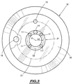
- Figure 3 illustrates the centrifuge of Figure 1 in which the rotor 2 with nacelles 6 has been replaced by a rotor 18 of generally frustoconical shape converging upwards.
- the rotor 18 has several housings 19 for bulbs or other containers intended to contain products to be centrifuged. One accommodation 19 is visible thanks to the cutaway of FIG. 3.
- the rotor 18 is surmounted by a single cover 20 for closing the housings 19.
- the cover 20 is itself surmounted by a central crown 21 supporting four magnets 11. These magnets 11 are regularly distributed angularly and are substantially arranged on a circle C2 centered on the axis A and of radius R2.
- the command 4 ensures, as before, a preliminary step of checking the presence of the cover 20.
- the unit 4 commands the stop of the motor 3. Otherwise, the centrifugation cycle is performed normally.
- the centrifuge 1 therefore makes it possible to limit the risks of centrifugation a rotor in the absence of a closure cover for a receiving housing of product to be centrifuged.
- all the rotors which can be used with the centrifuge 1 are with four magnets, or more generally the same number magnets to simplify the microprocessor programming algorithm of the control unit 4.
- different types of rotor can be equipped with a different number of magnets.
- the centrifuge 1 is then preferably equipped with means for detecting the type of rotor mounted on the motor 3, to determine the number of magnets 11 to be detected per revolution of the rotor, during the prior step of checking for the presence of the cover (s).
- the arrangement of sensors 13 and 14 at different levels relative to to axis A ensures, for the different types of rotor usable with the centrifuge 1, that the distance between the magnets 11 to be detected and the sensor 13 or 14 next to which they will pass is less than about 30 mm. So, the risks that the sensors 13 and 14 do not detect a magnet 11 passing through look of these are weak.
- the number of sensors 13 and 14 can be more important, these sensors being preferably arranged on circles centered on axis A and with different radii, and possibly at different levels with respect to axis A.
- magnetic means 11, 13 and 14 for detecting the presence of cover (s) allows satisfactory detection, even when the rotor is placed in a refrigerated enclosure. Indeed, the functioning of these magnetic detection means is relatively insensitive to phenomena of condensation that may appear in such an enclosure.
- the detection means can however be optical or ultrasonic means and, more generally, the magnets 11 and the sensors 13 and 14 can be replaced by elements to be detected and corresponding sensors, that is to say capable of detecting these elements.
Landscapes
- Centrifugal Separators (AREA)
Abstract
Description
- lesdits moyens de contrôle comprennent au moins un élément à détecter sur chaque couvercle et au moins un capteur correspondant,
- la centrifugeuse comprend une unité de commande du moteur adaptée pour assurer une étape de contrôle de la présence pour chaque logement du couvercle associé, étape au cours de laquelle ladite unité commande l'entraínement en rotation du rotor, compare le nombre d'élément(s) détecté(s) avec le nombre total d'élément(s) à détecter si chaque couvercle était présent, et empêche l'exécution d'un cycle de centrifugation au cas où le nombre d'élément(s) détecté(s) est inférieur au nombre total d'élément(s) à détecter,
- l'unité de commande est adaptée pour assurer l'étape de contrôle avant d'exécuter chaque cycle de centrifugation du rotor,
- pendant ladite étape de contrôle, l'unité de commande commande l'entraínement en rotation du rotor à une vitesse inférieure à environ 50 tr/mn,
- la centrifugeuse comprend des moyens de détection du type du rotor monté sur le moteur, et l'unité de commande est adaptée pour déterminer le nombre total d'élément(s) à détecter en fonction du type du rotor détecté,
- l'unité de commande comprend des moyens de mémorisation dans lesquels est stocké un nombre total fixe d'élément(s) à détecter quel que soit le type du rotor monté sur le moteur,
- lesdits moyens de contrôle comprennent plusieurs capteurs disposés à des distances différentes de l'axe de rotation,
- plusieurs desdits capteurs sont disposés à des niveaux différents par rapport à l'axe de rotation,
- chaque élément à détecter est un aimant.
- la figure 1 est une vue schématique latérale d'une centrifugeuse selon l'invention,
- la figure 2 est une vue schématique de dessus et agrandie, illustrant la position radiale respective du rotor et des capteurs de la centrifugeuse de la figure 1, et
- la figure 3 est une vue analogue à la figure 2, partiellement arrachée, illustrant l'utilisation dans la centrifugeuse de la figure 1 d'un autre type de rotor.
Claims (11)
- Centrifugeuse (1), du type comprenant un rotor (2 ; 18), qui présente au moins un logement (6 ; 19) de réception d'un produit à centrifuger et un couvercle associé (8 ; 20) de fermeture dudit logement, la centrifugeuse comprenant également un moteur (3) sur lequel le rotor est monté pour l'entraíner en rotation autour d'un axe de rotation (A), caractérisée en ce qu'elle comprend des moyens (4, 11, 13, 14, 16) de contrôle de la présence, pour chaque logement (6 ; 19), du couvercle associé pour empêcher l'exécution d'un cycle de centrifugation au cas où le couvercle (8 ; 20) d'un logement serait absent.
- Centrifugeuse selon la revendication 1, caractérisée en ce que lesdits moyens de contrôle comprennent au moins un élément (11) à détecter sur chaque couvercle (8 ; 20) et au moins un capteur correspondant.
- Centrifugeuse selon la revendication 2, caractérisée en ce qu'elle comprend une unité (4) de commande du moteur (3) adaptée pour assurer une étape de contrôle de la présence pour chaque logement (6 ; 19) du couvercle (8 ; 20) associé, étape au cours de laquelle ladite unité (4) commande l'entraínement en rotation du rotor (2 ; 18), compare le nombre d'élément(s) (11) détecté(s) avec le nombre total d'élément(s) à détecter si chaque couvercle (8 ; 20) était présent, et empêche l'exécution d'un cycle de centrifugation au cas où le nombre d'élément(s) détecté(s) (11) est inférieur au nombre total d'élément(s) (11) à détecter.
- Centrifugeuse selon la revendication 3, caractérisée en ce que l'unité de commande (4) est adaptée pour assurer l'étape de contrôle avant d'exécuter chaque cycle de centrifugation du rotor.
- Centrifugeuse selon la revendication 3 ou 4, caractérisée en ce que, pendant ladite étape de contrôle, l'unité de commande (4) commande l'entraínement en rotation du rotor à une vitesse où aucun aérosol ne risque de se former.
- Centrifugeuse selon l'une quelconque des revendications 3 à 5, caractérisée en ce qu'elle comprend des moyens de détection du type du rotor monté sur le moteur (3), et en ce que l'unité de commande (4) est adaptée pour déterminer le nombre total d'élément(s) (11) à détecter en fonction du type du rotor détecté.
- Centrifugeuse selon l'une quelconque des revendications 2 à 6, caractérisée en ce que l'unité de commande (4) comprend des moyens de mémorisation dans lesquels est stocké un nombre total fixe d'élément(s) (11) à détecter quel que soit le type du rotor monté sur le moteur (3).
- Centrifugeuse selon l'une quelconque des revendications 2 à 7, caractérisée en ce que lesdits moyens de contrôle comprennent plusieurs capteurs (13, 14) disposés à des distances (R1, R2) différentes de l'axe de rotation (A).
- Centrifugeuse selon la revendication 8, caractérisée en ce que plusieurs desdits capteurs (13, 14) sont disposés à des niveaux différents par rapport à l'axe de rotation (A).
- Centrifugeuse selon l'une quelconque des revendications 2 à 9, caractérisée en ce que chaque élément (11) à détecter est un aimant.
- Ensemble comprenant une centrifugeuse selon l'une quelconque des revendications 2 à 10 et plusieurs rotors pouvant être montés sur le moteur (3) de la centrifugeuse (1), chaque rotor présentant au moins un logement (6 ; 19) de réception d'un produit à centrifuger et un couvercle associé (8 ; 20) de fermeture dudit logement, caractérisé en ce que chaque rotor (2 ; 18) comprend le même nombre d'élément(s) (11) à détecter.
Applications Claiming Priority (2)
| Application Number | Priority Date | Filing Date | Title |
|---|---|---|---|
| FR9912580 | 1999-10-08 | ||
| FR9912580A FR2799395B1 (fr) | 1999-10-08 | 1999-10-08 | Centrifugeuse a rotor presentant au moins un logement de reception d'un produit a centrifuger et un couvercle associe de fermeture, et ensemble comprenant une telle centrifugeuse et plusieurs rotors |
Publications (2)
| Publication Number | Publication Date |
|---|---|
| EP1090688A1 true EP1090688A1 (fr) | 2001-04-11 |
| EP1090688B1 EP1090688B1 (fr) | 2005-08-17 |
Family
ID=9550720
Family Applications (1)
| Application Number | Title | Priority Date | Filing Date |
|---|---|---|---|
| EP00402726A Expired - Lifetime EP1090688B1 (fr) | 1999-10-08 | 2000-10-04 | Centrifugeuse à rotor présentant au moins un logement de réception d'un produit à centrifuger et un couvercle associé de fermeture |
Country Status (6)
| Country | Link |
|---|---|
| US (1) | US6383126B1 (fr) |
| EP (1) | EP1090688B1 (fr) |
| JP (1) | JP2001157856A (fr) |
| AT (1) | ATE302066T1 (fr) |
| DE (1) | DE60021974T2 (fr) |
| FR (1) | FR2799395B1 (fr) |
Cited By (4)
| Publication number | Priority date | Publication date | Assignee | Title |
|---|---|---|---|---|
| FR2951965A1 (fr) * | 2009-11-04 | 2011-05-06 | Bms Internat | Centrifugeuse integrant des moyens tachymetriques montes dans une partie superieure de l'enceinte, en particulier montes sur le couvercle |
| FR2951963A1 (fr) * | 2009-11-04 | 2011-05-06 | Bms Internat | Centrifugeuse comprenant des moyens de detection d'un defaut d'horizontalite susceptibles |
| DE10303249B4 (de) * | 2002-02-01 | 2014-03-20 | Hitachi Koki Co., Ltd. | Zentrifuge |
| CN113058756A (zh) * | 2021-03-18 | 2021-07-02 | 凡亚坤 | 一种可自动调节的生物实验装置 |
Families Citing this family (7)
| Publication number | Priority date | Publication date | Assignee | Title |
|---|---|---|---|---|
| EP1270078B1 (fr) * | 2001-06-22 | 2004-09-15 | Jouan Italia S.R.L. | Appareil et procédé pour charger et décharger, automatiquement de godets pour centrifugeuse |
| US7837607B2 (en) * | 2006-12-13 | 2010-11-23 | Thermo Fisher Scientific Inc. | Centrifuge rotor assembly and method of connection thereof |
| CN106102921B (zh) * | 2014-01-22 | 2019-10-18 | 赛拉诺斯知识产权有限责任公司 | 用于对小体积样品进行高速离心的方法 |
| JP6572009B2 (ja) * | 2015-06-19 | 2019-09-04 | 株式会社久保田製作所 | 遠心分離機のスイング型ロータ用バケット |
| EP3755160B1 (fr) * | 2018-04-20 | 2021-11-03 | Pacotrade AG | Dispositif pour broyer des denrées alimentaires surgelées se présentant sous la forme d'un bloc |
| CN111804445B (zh) * | 2020-07-14 | 2021-06-11 | 无锡市妇幼保健院 | 一种离心机运行中自动锁定的生物细胞试管架 |
| CN112354689A (zh) * | 2020-11-12 | 2021-02-12 | 李治明 | 一种提高安全性的旋转式生物离心机 |
Citations (3)
| Publication number | Priority date | Publication date | Assignee | Title |
|---|---|---|---|---|
| US4342419A (en) * | 1980-10-31 | 1982-08-03 | Beckman Instruments, Inc. | Safety cover for centrifuge bucket |
| US4464161A (en) * | 1982-02-19 | 1984-08-07 | Kabushiki Kaisha Kubota Seisakusho | Safety device for centrifugal separators |
| WO1996001697A1 (fr) * | 1994-07-07 | 1996-01-25 | Beckman Instruments, Inc. | Identification automatique d'un rotor basee sur un signal emis par le rotor |
Family Cites Families (9)
| Publication number | Priority date | Publication date | Assignee | Title |
|---|---|---|---|---|
| US2779537A (en) * | 1950-08-01 | 1957-01-29 | Samuel D Jarvis | Fluid contacting apparatus |
| US3970245A (en) * | 1975-05-21 | 1976-07-20 | Dr. Molter Gmbh | Universal centrifuge |
| FI864811L (fi) * | 1985-12-11 | 1987-06-12 | Kontron Holding Ag | Centrifug. |
| EP0334897B1 (fr) * | 1986-12-10 | 1993-09-15 | E.I. Du Pont De Nemours And Company | Systeme de reconnaissance de rotors |
| US5235864A (en) * | 1990-12-21 | 1993-08-17 | E. I. Du Pont De Nemours And Company | Centrifuge rotor identification system based on rotor velocity |
| US5221250A (en) * | 1991-01-07 | 1993-06-22 | Beckman Instruments, Inc. | Coding of maximum operating speed on centrifuge rotors and detection thereof |
| JP2514554B2 (ja) * | 1992-12-28 | 1996-07-10 | 株式会社久保田製作所 | 遠心機 |
| JPH09117695A (ja) * | 1995-10-26 | 1997-05-06 | Hitachi Koki Co Ltd | 遠心機 |
| US5649893A (en) * | 1996-05-22 | 1997-07-22 | Hitachi Koki Co., Ltd. | Centrifugal apparatus having series-implemented protection means |
-
1999
- 1999-10-08 FR FR9912580A patent/FR2799395B1/fr not_active Expired - Fee Related
-
2000
- 2000-10-04 AT AT00402726T patent/ATE302066T1/de not_active IP Right Cessation
- 2000-10-04 DE DE60021974T patent/DE60021974T2/de not_active Expired - Fee Related
- 2000-10-04 EP EP00402726A patent/EP1090688B1/fr not_active Expired - Lifetime
- 2000-10-05 US US09/679,644 patent/US6383126B1/en not_active Expired - Fee Related
- 2000-10-10 JP JP2000309039A patent/JP2001157856A/ja not_active Withdrawn
Patent Citations (3)
| Publication number | Priority date | Publication date | Assignee | Title |
|---|---|---|---|---|
| US4342419A (en) * | 1980-10-31 | 1982-08-03 | Beckman Instruments, Inc. | Safety cover for centrifuge bucket |
| US4464161A (en) * | 1982-02-19 | 1984-08-07 | Kabushiki Kaisha Kubota Seisakusho | Safety device for centrifugal separators |
| WO1996001697A1 (fr) * | 1994-07-07 | 1996-01-25 | Beckman Instruments, Inc. | Identification automatique d'un rotor basee sur un signal emis par le rotor |
Cited By (5)
| Publication number | Priority date | Publication date | Assignee | Title |
|---|---|---|---|---|
| DE10303249B4 (de) * | 2002-02-01 | 2014-03-20 | Hitachi Koki Co., Ltd. | Zentrifuge |
| FR2951965A1 (fr) * | 2009-11-04 | 2011-05-06 | Bms Internat | Centrifugeuse integrant des moyens tachymetriques montes dans une partie superieure de l'enceinte, en particulier montes sur le couvercle |
| FR2951963A1 (fr) * | 2009-11-04 | 2011-05-06 | Bms Internat | Centrifugeuse comprenant des moyens de detection d'un defaut d'horizontalite susceptibles |
| WO2011054901A1 (fr) * | 2009-11-04 | 2011-05-12 | Awel International | Centrifugeuse intégrant des moyens tachymétriques montés dans une partie supérieure de l'enceinte, en particulier montés sur le couvercle |
| CN113058756A (zh) * | 2021-03-18 | 2021-07-02 | 凡亚坤 | 一种可自动调节的生物实验装置 |
Also Published As
| Publication number | Publication date |
|---|---|
| EP1090688B1 (fr) | 2005-08-17 |
| DE60021974T2 (de) | 2006-05-18 |
| JP2001157856A (ja) | 2001-06-12 |
| US6383126B1 (en) | 2002-05-07 |
| DE60021974D1 (de) | 2005-09-22 |
| ATE302066T1 (de) | 2005-09-15 |
| FR2799395B1 (fr) | 2001-12-21 |
| FR2799395A1 (fr) | 2001-04-13 |
Similar Documents
| Publication | Publication Date | Title |
|---|---|---|
| EP1090688B1 (fr) | Centrifugeuse à rotor présentant au moins un logement de réception d'un produit à centrifuger et un couvercle associé de fermeture | |
| EP0962249B1 (fr) | Agitateur à entraínement magnétique | |
| EP1953095B1 (fr) | Dispositif de remplissage d'au moins deux bacs de collecte de déchets | |
| EP2496355B1 (fr) | Centrifugeuse intégrant des moyens tachymétriques montés dans une partie supérieure de l'enceinte, en particulier montés sur le couvercle | |
| EP1533465B1 (fr) | Dispositif d'entraînement d'un écran de fermeture ou de protection solaire et installation comportant un tel dispositif | |
| FR2810407A1 (fr) | Appareil pour l'analyse d'echantillons | |
| FR2982586A1 (fr) | Compartiment a bagages pour avion avec support a bagages | |
| EP0287484B1 (fr) | Perfectionnements aux machines industrielles de traitement à cuve tournante | |
| FR2858251A1 (fr) | Procede pour equilibrer un plateau rotatif d'une centrifugeuse et centrifugeuse mettant en oeuvre le procede | |
| WO2013189594A1 (fr) | Nacelle de centrifugeuse dotee d'un couvercle et centrifugeuse destinee a recevoir ladite nacelle | |
| FR2629370A1 (fr) | Installation robotisee d'analyses comportant une centrifugeuse | |
| CA2072402C (fr) | Dispositif pour prelever et restituer une quantite predeterminee et constante d'un liquide | |
| EP1137491A1 (fr) | Dispositif de centrifugation pour automate de laboratoire | |
| EP0983924B1 (fr) | Dispositif de volant de manoeuvre | |
| FR2675902A1 (fr) | Installation de prelevement d'echantillons fluides dans une zone confinee. | |
| FR2897290A1 (fr) | Outil de coupe perfectionne pour appareil de preparation alimentaire, et appareil comportant un tel outil | |
| EP1064528B1 (fr) | Dispositif pour l'equilibrage d'un element tournant de machine en cours de rotation | |
| FR2674331A1 (fr) | Equilibreuse de roues ou analogues. | |
| FR2650889A1 (fr) | Appareil pour la detection du balourd d'une roue d'automobile en vue de l'equilibrage de celle-ci, et capteur potentiometrique destine a equiper un tel appareil | |
| FR2552742A1 (fr) | Dispositif de transfert d'elements, en particulier de conteneurs pour produits pharmaceutiques | |
| EP1996489A1 (fr) | Conteneur securise pour la reception de dechets | |
| FR2531777A1 (fr) | Appareil de prelevement d'echantillons de produits pulverulents ou granuleux | |
| FR2797657A1 (fr) | Systeme de volet comportant un volet roulant | |
| BE1019435A3 (fr) | Plateau tournant pour roulette automatique et dispositif de roulette comportant un tel plateau. | |
| FR3072941A3 (fr) | Dispositif de liaison et d'articulation des plateaux cycliques d'helicoptere sur un coulisseau lie par cannelures a l'arbre rotor |
Legal Events
| Date | Code | Title | Description |
|---|---|---|---|
| PUAI | Public reference made under article 153(3) epc to a published international application that has entered the european phase |
Free format text: ORIGINAL CODE: 0009012 |
|
| AK | Designated contracting states |
Kind code of ref document: A1 Designated state(s): AT BE CH CY DE DK ES FI FR GB GR IE IT LI LU MC NL PT SE |
|
| AX | Request for extension of the european patent |
Free format text: AL;LT;LV;MK;RO;SI |
|
| 17P | Request for examination filed |
Effective date: 20011004 |
|
| AKX | Designation fees paid |
Free format text: AT BE CH CY DE DK ES FI FR GB GR IE IT LI LU MC NL PT SE |
|
| GRAP | Despatch of communication of intention to grant a patent |
Free format text: ORIGINAL CODE: EPIDOSNIGR1 |
|
| GRAS | Grant fee paid |
Free format text: ORIGINAL CODE: EPIDOSNIGR3 |
|
| GRAA | (expected) grant |
Free format text: ORIGINAL CODE: 0009210 |
|
| AK | Designated contracting states |
Kind code of ref document: B1 Designated state(s): AT BE CH CY DE DK ES FI FR GB GR IE IT LI LU MC NL PT SE |
|
| PG25 | Lapsed in a contracting state [announced via postgrant information from national office to epo] |
Ref country code: AT Free format text: LAPSE BECAUSE OF FAILURE TO SUBMIT A TRANSLATION OF THE DESCRIPTION OR TO PAY THE FEE WITHIN THE PRESCRIBED TIME-LIMIT Effective date: 20050817 Ref country code: NL Free format text: LAPSE BECAUSE OF FAILURE TO SUBMIT A TRANSLATION OF THE DESCRIPTION OR TO PAY THE FEE WITHIN THE PRESCRIBED TIME-LIMIT Effective date: 20050817 Ref country code: FI Free format text: LAPSE BECAUSE OF FAILURE TO SUBMIT A TRANSLATION OF THE DESCRIPTION OR TO PAY THE FEE WITHIN THE PRESCRIBED TIME-LIMIT Effective date: 20050817 Ref country code: IE Free format text: LAPSE BECAUSE OF FAILURE TO SUBMIT A TRANSLATION OF THE DESCRIPTION OR TO PAY THE FEE WITHIN THE PRESCRIBED TIME-LIMIT Effective date: 20050817 |
|
| REG | Reference to a national code |
Ref country code: GB Ref legal event code: FG4D Free format text: NOT ENGLISH |
|
| REG | Reference to a national code |
Ref country code: CH Ref legal event code: EP |
|
| REG | Reference to a national code |
Ref country code: IE Ref legal event code: FG4D Free format text: LANGUAGE OF EP DOCUMENT: FRENCH |
|
| REF | Corresponds to: |
Ref document number: 60021974 Country of ref document: DE Date of ref document: 20050922 Kind code of ref document: P |
|
| PG25 | Lapsed in a contracting state [announced via postgrant information from national office to epo] |
Ref country code: CY Free format text: LAPSE BECAUSE OF FAILURE TO SUBMIT A TRANSLATION OF THE DESCRIPTION OR TO PAY THE FEE WITHIN THE PRESCRIBED TIME-LIMIT Effective date: 20051004 |
|
| PG25 | Lapsed in a contracting state [announced via postgrant information from national office to epo] |
Ref country code: MC Free format text: LAPSE BECAUSE OF NON-PAYMENT OF DUE FEES Effective date: 20051031 Ref country code: BE Free format text: LAPSE BECAUSE OF NON-PAYMENT OF DUE FEES Effective date: 20051031 Ref country code: CH Free format text: LAPSE BECAUSE OF NON-PAYMENT OF DUE FEES Effective date: 20051031 Ref country code: LU Free format text: LAPSE BECAUSE OF NON-PAYMENT OF DUE FEES Effective date: 20051031 Ref country code: LI Free format text: LAPSE BECAUSE OF NON-PAYMENT OF DUE FEES Effective date: 20051031 |
|
| PG25 | Lapsed in a contracting state [announced via postgrant information from national office to epo] |
Ref country code: SE Free format text: LAPSE BECAUSE OF FAILURE TO SUBMIT A TRANSLATION OF THE DESCRIPTION OR TO PAY THE FEE WITHIN THE PRESCRIBED TIME-LIMIT Effective date: 20051117 Ref country code: DK Free format text: LAPSE BECAUSE OF FAILURE TO SUBMIT A TRANSLATION OF THE DESCRIPTION OR TO PAY THE FEE WITHIN THE PRESCRIBED TIME-LIMIT Effective date: 20051117 Ref country code: GR Free format text: LAPSE BECAUSE OF FAILURE TO SUBMIT A TRANSLATION OF THE DESCRIPTION OR TO PAY THE FEE WITHIN THE PRESCRIBED TIME-LIMIT Effective date: 20051117 |
|
| PG25 | Lapsed in a contracting state [announced via postgrant information from national office to epo] |
Ref country code: ES Free format text: LAPSE BECAUSE OF FAILURE TO SUBMIT A TRANSLATION OF THE DESCRIPTION OR TO PAY THE FEE WITHIN THE PRESCRIBED TIME-LIMIT Effective date: 20051128 |
|
| GBT | Gb: translation of ep patent filed (gb section 77(6)(a)/1977) |
Effective date: 20051111 |
|
| PG25 | Lapsed in a contracting state [announced via postgrant information from national office to epo] |
Ref country code: PT Free format text: LAPSE BECAUSE OF FAILURE TO SUBMIT A TRANSLATION OF THE DESCRIPTION OR TO PAY THE FEE WITHIN THE PRESCRIBED TIME-LIMIT Effective date: 20060117 |
|
| NLV1 | Nl: lapsed or annulled due to failure to fulfill the requirements of art. 29p and 29m of the patents act | ||
| REG | Reference to a national code |
Ref country code: IE Ref legal event code: FD4D |
|
| REG | Reference to a national code |
Ref country code: CH Ref legal event code: PL |
|
| PLBE | No opposition filed within time limit |
Free format text: ORIGINAL CODE: 0009261 |
|
| STAA | Information on the status of an ep patent application or granted ep patent |
Free format text: STATUS: NO OPPOSITION FILED WITHIN TIME LIMIT |
|
| 26N | No opposition filed |
Effective date: 20060518 |
|
| BERE | Be: lapsed |
Owner name: JOUAN Effective date: 20051031 |
|
| PGFP | Annual fee paid to national office [announced via postgrant information from national office to epo] |
Ref country code: DE Payment date: 20081027 Year of fee payment: 9 |
|
| PGFP | Annual fee paid to national office [announced via postgrant information from national office to epo] |
Ref country code: IT Payment date: 20081030 Year of fee payment: 9 |
|
| PGFP | Annual fee paid to national office [announced via postgrant information from national office to epo] |
Ref country code: FR Payment date: 20081030 Year of fee payment: 9 |
|
| PGFP | Annual fee paid to national office [announced via postgrant information from national office to epo] |
Ref country code: GB Payment date: 20081029 Year of fee payment: 9 |
|
| REG | Reference to a national code |
Ref country code: FR Ref legal event code: ST Effective date: 20100630 |
|
| PG25 | Lapsed in a contracting state [announced via postgrant information from national office to epo] |
Ref country code: FR Free format text: LAPSE BECAUSE OF NON-PAYMENT OF DUE FEES Effective date: 20091102 Ref country code: DE Free format text: LAPSE BECAUSE OF NON-PAYMENT OF DUE FEES Effective date: 20100501 |
|
| PG25 | Lapsed in a contracting state [announced via postgrant information from national office to epo] |
Ref country code: GB Free format text: LAPSE BECAUSE OF NON-PAYMENT OF DUE FEES Effective date: 20091004 |
|
| PG25 | Lapsed in a contracting state [announced via postgrant information from national office to epo] |
Ref country code: IT Free format text: LAPSE BECAUSE OF NON-PAYMENT OF DUE FEES Effective date: 20091004 |