EP1092585A2 - Siège de véhicule doté d'un dispositif de protection du cou en cas de choc arrière - Google Patents
Siège de véhicule doté d'un dispositif de protection du cou en cas de choc arrière Download PDFInfo
- Publication number
- EP1092585A2 EP1092585A2 EP01102204A EP01102204A EP1092585A2 EP 1092585 A2 EP1092585 A2 EP 1092585A2 EP 01102204 A EP01102204 A EP 01102204A EP 01102204 A EP01102204 A EP 01102204A EP 1092585 A2 EP1092585 A2 EP 1092585A2
- Authority
- EP
- European Patent Office
- Prior art keywords
- frame
- backrest
- back frame
- connecting rod
- angular position
- Prior art date
- Legal status (The legal status is an assumption and is not a legal conclusion. Google has not performed a legal analysis and makes no representation as to the accuracy of the status listed.)
- Granted
Links
- 230000004224 protection Effects 0.000 title description 2
- 230000007246 mechanism Effects 0.000 claims abstract description 35
- 230000033001 locomotion Effects 0.000 claims description 12
- 239000002184 metal Substances 0.000 claims description 9
- 229910052751 metal Inorganic materials 0.000 claims description 9
- 238000006073 displacement reaction Methods 0.000 claims description 8
- 238000010521 absorption reaction Methods 0.000 claims description 6
- 229920003023 plastic Polymers 0.000 claims description 3
- 239000004033 plastic Substances 0.000 claims description 3
- 238000012550 audit Methods 0.000 claims description 2
- 230000008093 supporting effect Effects 0.000 claims description 2
- 210000000056 organ Anatomy 0.000 claims 1
- 230000000903 blocking effect Effects 0.000 abstract description 5
- 230000005540 biological transmission Effects 0.000 description 10
- 230000002427 irreversible effect Effects 0.000 description 6
- 230000036961 partial effect Effects 0.000 description 5
- 230000035939 shock Effects 0.000 description 5
- 230000002829 reductive effect Effects 0.000 description 2
- 206010039203 Road traffic accident Diseases 0.000 description 1
- 208000027418 Wounds and injury Diseases 0.000 description 1
- 230000006378 damage Effects 0.000 description 1
- 230000000694 effects Effects 0.000 description 1
- 208000014674 injury Diseases 0.000 description 1
- 210000004197 pelvis Anatomy 0.000 description 1
- 230000000750 progressive effect Effects 0.000 description 1
Images



Classifications
-
- B—PERFORMING OPERATIONS; TRANSPORTING
- B60—VEHICLES IN GENERAL
- B60N—SEATS SPECIALLY ADAPTED FOR VEHICLES; VEHICLE PASSENGER ACCOMMODATION NOT OTHERWISE PROVIDED FOR
- B60N2/00—Seats specially adapted for vehicles; Arrangement or mounting of seats in vehicles
- B60N2/24—Seats specially adapted for vehicles; Arrangement or mounting of seats in vehicles for particular purposes or particular vehicles
- B60N2/42—Seats specially adapted for vehicles; Arrangement or mounting of seats in vehicles for particular purposes or particular vehicles the seat constructed to protect the occupant from the effect of abnormal g-forces, e.g. crash or safety seats
-
- B—PERFORMING OPERATIONS; TRANSPORTING
- B60—VEHICLES IN GENERAL
- B60N—SEATS SPECIALLY ADAPTED FOR VEHICLES; VEHICLE PASSENGER ACCOMMODATION NOT OTHERWISE PROVIDED FOR
- B60N2/00—Seats specially adapted for vehicles; Arrangement or mounting of seats in vehicles
- B60N2/02—Seats specially adapted for vehicles; Arrangement or mounting of seats in vehicles the seat or part thereof being movable, e.g. adjustable
- B60N2/22—Seats specially adapted for vehicles; Arrangement or mounting of seats in vehicles the seat or part thereof being movable, e.g. adjustable the back-rest being adjustable
- B60N2/2222—Seats specially adapted for vehicles; Arrangement or mounting of seats in vehicles the seat or part thereof being movable, e.g. adjustable the back-rest being adjustable the back-rest having two or more parts
-
- B—PERFORMING OPERATIONS; TRANSPORTING
- B60—VEHICLES IN GENERAL
- B60N—SEATS SPECIALLY ADAPTED FOR VEHICLES; VEHICLE PASSENGER ACCOMMODATION NOT OTHERWISE PROVIDED FOR
- B60N2/00—Seats specially adapted for vehicles; Arrangement or mounting of seats in vehicles
- B60N2/80—Head-rests
- B60N2/806—Head-rests movable or adjustable
- B60N2/838—Tiltable
- B60N2/841—Tiltable characterised by their locking devices
- B60N2/847—Tiltable characterised by their locking devices with stepwise positioning
-
- B—PERFORMING OPERATIONS; TRANSPORTING
- B60—VEHICLES IN GENERAL
- B60N—SEATS SPECIALLY ADAPTED FOR VEHICLES; VEHICLE PASSENGER ACCOMMODATION NOT OTHERWISE PROVIDED FOR
- B60N2/00—Seats specially adapted for vehicles; Arrangement or mounting of seats in vehicles
- B60N2/80—Head-rests
- B60N2/806—Head-rests movable or adjustable
- B60N2/838—Tiltable
- B60N2/853—Tiltable characterised by their adjusting mechanisms, e.g. electric motors
-
- B—PERFORMING OPERATIONS; TRANSPORTING
- B60—VEHICLES IN GENERAL
- B60N—SEATS SPECIALLY ADAPTED FOR VEHICLES; VEHICLE PASSENGER ACCOMMODATION NOT OTHERWISE PROVIDED FOR
- B60N2/00—Seats specially adapted for vehicles; Arrangement or mounting of seats in vehicles
- B60N2/80—Head-rests
- B60N2/888—Head-rests with arrangements for protecting against abnormal g-forces, e.g. by displacement of the head-rest
Definitions
- the present invention relates to the seats of vehicles with neck protection devices in case of rear shock.
- the invention relates to a vehicle seat with a backrest which is surmounted a headrest and which has a rigid frame supporting a padding, this file presenting a face front which is intended to serve as support for the back of a passenger, the backrest frame being formed in two parts movable relative to each other, namely from a on the one hand, a lower part and on the other hand an upper part wearing the headrest, this upper part being pivotally mounted on the lower part around a axis of rotation between first and second positions angular, respectively inclined as far back as possible and as far forward as possible with respect to the part lower, the front side of the backrest presenting itself two upper and lower overlapping areas which are attached respectively to the lower and upper parts of the back frame, the upper part of the back frame having a support member which is arranged in the file below the level of the axis of rotation of said upper part so that when the vehicle is rear impacted, passenger back is pressed backwards on said support member by sinking into the padding of the file, so as to solicit the party
- WO-A-97/10117 describes an example of vehicle seat of the aforementioned type.
- the object of the present invention is in particular to improve seats of the genre in question.
- a seat of the kind in question is characterized in that the blocking device includes an adjustment mechanism driven by a control, this adjustment mechanism being adapted to move the upper part of the back frame between its first and second angular positions as a function of actuation of the control member, and to block said upper part of the back frame when the control member is not actuated, as long as said member support does not undergo a force directed towards the rear and greater than said predetermined value.
- FIG. 1 represents a vehicle seat 1, in particular a front seat of a motor vehicle, which comprises, on the one hand, a seat 2 mounted on the floor 3 of the vehicle, and on the other hand, a backrest 4 pivotally mounted on the seat 2 around a transverse horizontal axis X.
- Backrest 4 includes a rigid metal frame which supports a padding 4a, and which carries a headrest 5.
- folder 4 has one side front 6 which is intended to serve as support for the back of a passenger, this front panel subdividing itself into a lower zone 7 and an upper zone 8 whose inclination may vary when the vehicle is rear impacted, as will be explained below.
- the frame 9 of the backrest is formed in two movable parts one in relation to the other, namely on the one hand, a lower part 10 which is pivotally mounted on the seat 2 around the transverse axis X and which is integral with the lower part 7 of the front face of the backrest, and other apart, an upper part 11 which is pivotally mounted on the lower part 10 around an imaginary pivot axis X '( Figure 1) and which is integral with the upper zone 8 from the front of the backrest.
- the part lower 10 of the back frame has two flanges vertical side panels 12 which are pivotally mounted on the seat 2 around the transverse axis X and which are connected between them by a bottom rail.
- the flanges 12 have two lower grooves 14, of which only one is visible in FIG. 2, these lower grooves 14 being arranged in correspondence with each other on either side of the backrest and extending each up and back from a first end 15 to a second end 16.
- the two flanges 12 further comprise two upper grooves 17 which are arranged in correspondence with each other on either side of the file, and which each extend up and forward from a first end 18 to a second end 19.
- the upper part 11 of the frame of the backrest comprises a metal profile, for example tubular, which is folded into a general U shape, with a cross upper and two side branches 21 which are connected to each other toward their lower ends by a rigid cross member 22 (FIG. 2), slightly curved towards the back.
- a metal profile for example tubular, which is folded into a general U shape, with a cross upper and two side branches 21 which are connected to each other toward their lower ends by a rigid cross member 22 (FIG. 2), slightly curved towards the back.
- the crosspiece 22 is arranged inside the backrest 4, slightly above the level of the seat 2 and below of the level of the imaginary pivot axis X 'of the upper part 11 of the back frame (see figure 1).
- the frame 9 of the backrest further includes a blocking device which normally holds the part upper 11 of this frame in the position described above, called the first angular position.
- one of the lower grooves 14 is provided with teeth 30 which forms one of the longitudinal edges of this groove.
- the pivot 23 which moves in the groove 14 comprises a rotary member with two fingers 31 which extend parallel to axes X and X 'and which can be driven in rotation by a handle 32.
- an elastic metal wire 34 mounted on the flange 12 which includes the toothed groove 14, presses in permanently on the socket 33 so as to stress the fingers 31 towards the bottom of the teeth 30.
- the teeth 30, the fingers 31, the handle 32, the sleeve 33 and spring 34 thus constitute a mechanism maneuver 35 which allows, by rotating the handle 32, to adjust the inclination of the upper part 11 of the back frame in relation to the lower part 10.
- the operating mechanism 35 is irreversible, that is, it normally remains blocked as long as the handle 32 is not actuated.
- the plastic deformation progressive toothing 30 absorbs part of the energy of the shock, and the upper zone 8 of the front face of the backrest moves forward and upward with headrest 5, as explained above.
- the grooves 14, 17 are all devoid of notches, and the pivot 23 of one grooves 14 is secured with a connecting rod 36 provided of a rack 37 engaged with a pinion 38.
- This pinion 38 is pivotally mounted on the flange 12 corresponding, and it is coupled to a transmission mechanism irreversible 39, known per se in the state of the art, this transmission mechanism being itself controlled by a rotary handle 40.
- the connecting rod 36, its rack 37, the pinion 38, the transmission mechanism 39 and the handle 40 constitute thus an irreversible operating mechanism 41 which allows to vary, by actuating the handle 40, the distance between the pinion 38 and the pivot 23.
- the pinion 38 remains blocked as long as the handle 40 is not actuated, even if an effort is exerted on the upper part 11 of the backrest.
- the connecting rod 36 is suitable for gradually deform plastically allowing the upper part 11 of the backrest to pivot until it second angular position when this upper has not already been adjusted in said second angular position, as explained above next to the first embodiment.
- the connecting rod 36 is advantageously in the form of a sheet metal plate with a wedge-shaped slot 42 which extends between, on the one hand a first end 43 forming an enlarged portion in which the pivot 23 is received without game, and on the other hand a thinner end 44, the part 45 of the slot 42, which is located between the pivot 23 and the end 44, being narrow enough to prevent normally the passage of the pivot 23.
- the slot 42 is arranged substantially in correspondence with the adjacent slot 14 when the upper part 11 of the back frame is in its first angular position ( Figure 6).
- the side flanges 12 of the lower part of the back frame always have upper grooves 17 extending up and forward and each receiving a pivot 24 secured to the upper part 11 of the frame of the folder.
- these upper grooves 17 are smooth.
- the angular position of the upper part 11 of the backrest frame can be adjusted by means of a rotary handle 40 which drives a mechanism transmission 39 of "irreversible" type known in oneself.
- the transmission mechanism 39 can for example be of the type disclosed in DE-37 34363 in document US-5,593,210, in document FR-843,668, or also in document US-1,529,248.
- the housing 39a of this transmission mechanism is fixed on the flange 12, while the input shaft 39b of said mechanism is secured to the handle 40, the shaft of outlet 39c of said mechanism being secured with a pinion 50 which meshes with a toothing 51 in an arc, formed at one end of a connecting rod 52 whose other end is swivel mounted on the flange 12.
- connecting rod 52 is connected to the lower end of the upper part 11 of the back frame via a pivot 54 which, preferably, also secures the crosspiece 22 with said end lower part of upper part 11 of the backrest.
- a similar connecting rod (without teeth) is provided on the other side of the seat, with a connecting bar between the two connecting rods to synchronize their movement.
- the transmission mechanism 39 is adapted to immobilize the pinion 50 in the absence of actuation of the handle 40, as long as a predetermined torque is not applied said pinion 50.
- the rod 56 is biased in its direction of rotation corresponding to the displacement of the pivot 55 towards the front, by means of a spring 58, for example a spring of traction of which one end is fixed to a hook 59 of the rod and the other end of which is fixed in a hole 60 of an intermediate metal piece 61 secured with the upper part 11 of the backrest.
- a spring 58 for example a spring of traction of which one end is fixed to a hook 59 of the rod and the other end of which is fixed in a hole 60 of an intermediate metal piece 61 secured with the upper part 11 of the backrest.
- the angular position of the rod 56, and therefore the angular position of the upper frame 11 of the backrest, is adjusted by means of an adjustment mechanism 41 comprising a handle 40, an irreversible transmission mechanism 39 and a pinion 50 identical or similar to those described above with reference to Figures 13 and 14.
- the pinion 50 meshes with a circular toothing 62 a cam 63 pivotally mounted on the flange 12 around a pivot 64, this cam 63 having a bearing edge 65 rear-facing, which is in contact with pivot 55 of the rod 56, at the lower end of the upper part 11 of the back frame.
- spring 58 is strong enough to hold the pivot 55 in abutment against the bearing edge 65 of the cam 63.
- the impact energy is also absorbed, at the end of movement of the upper part 11 of the back frame, by the intermediate pieces 61 above, welded to the top 11 of the back frame at the pivots 24 and 55, on either side of the file.
- Intermediate parts can consist of example in U-shaped sections whose branches 66 are oriented towards the upper part 11 of the frame of the file and whose base 67 has a cutout leg 68 in sheet metal part 61.
- Each tab 68 is preferably folded 180 ° from so as to extend substantially horizontally forward parallel to the flange 12.
- each tab 68 has a hole 69 or the like. fixing means for fixing the pivot 24 or 55 corresponding.
- the intermediate parts 61 first resist during that the upper part 11 of the back frame passes in its second angular position. Then when the pivots 24 and 55 are in the stop position, the legs 68 tear the sheet metal of the base 67 of the U-sections constituting intermediate parts 61, which makes it possible to still absorb part of the shock energy.
- the pinion 50 could if necessary be driven by a totally irreversible control mechanism, especially powered by an electric motor.
- the upper grooves 17 and the associated pivots 24 could be replaced by links by rods.
Landscapes
- Engineering & Computer Science (AREA)
- Aviation & Aerospace Engineering (AREA)
- Transportation (AREA)
- Mechanical Engineering (AREA)
- Seats For Vehicles (AREA)
- Chairs For Special Purposes, Such As Reclining Chairs (AREA)
- Chair Legs, Seat Parts, And Backrests (AREA)
Abstract
Description
- d'une part, l'appui-tête se rapproche de la nuque du passager en la retenant de façon plus efficace,
- et d'autre part, on diminue l'inclinaison vers l'arrière de la partie haute du dossier : ainsi, le passager du siège a moins tendance à être projeté vers le haut par effet de rampe, ce qui évite que la nuque du passager ne se retrouve au-dessus du niveau de l'appui-tête.
- la partie supérieure de l'armature du dossier est montée sur la partie inférieure pour se déplacer vers le haut en même temps qu'elle pivote vers l'avant ;
- la partie supérieure de l'armature du dossier se présente sous la forme d'un cadre qui comporte une traverse inférieure horizontale, laquelle traverse constitue ledit organe d'appui ;
- le mécanisme de réglage comprend au moins un organe d'entraínement rotatif en prise avec une denture, cet organe d'entraínement et cette denture étant reliés l'un à la partie supérieure de l'armature du dossier et l'autre à la partie inférieure de cette armature pour qu'un déplacement de l'organe d'entraínement sur la denture corresponde à une variation d'inclinaison de la partie supérieure de l'armature du dossier, et la denture étant adaptée pour se déformer progressivement plastiquement en permettant à l'organe d'entraínement de se déplacer sans rotation le long de ladite denture en cas de choc arrière, cette denture constituant ainsi les moyens d'absorption d'énergie ;
- la partie supérieure de l'armature du dossier est montée pivotante sur la partie inférieure de cette armature au moyen de pivots coulissant dans des glissières, au moins un de ces pivots comprenant ledit organe d'entraínement, et ladite denture étant formée dans la glissière correspondante ;
- la partie supérieure de l'armature du dossier est montée pivotante sur la partie inférieure de cette armature au moyen de pivots coulissant dans des glissières, au moins un de ces pivots étant solidarisé avec une bielle, ce pivot et la glissière correspondante étant solidaires l'une de la partie supérieure de l'armature du dossier, et l'autre de la partie inférieure de cette armature, la bielle étant déplaçable au moyen dudit mécanisme de réglage par rapport à la partie de l'armature du dossier qui comprend ladite glissière, de façon qu'un déplacement de la bielle entraíne un déplacement concomitant des pivots dans leurs glissières, et la bielle étant déformable plastiquement en cas de choc arrière en constituant ainsi les moyens d'absorption d'énergie ;
- le mécanisme de réglage comprend un pignon monté rotatif sur la partie de l'armature du dossier qui comprend la glissière correspondant à la bielle, ce pignon étant en prise avec une crémaillère formée dans la bielle;
- la bielle se présente sous la forme d'une plaque de tôle qui est pourvue d'une fente s'étendant entre des première et deuxième extrémités, cette fente comportant une partie élargie à sa première extrémité et une partie resserrée qui s'étend depuis ladite partie élargie jusqu'à la deuxième extrémité de la fente, le pivot qui est solidarisé avec la bielle étant engagé sensiblement sans jeu dans ladite partie élargie, ladite fente étant disposée sensiblement en correspondance avec la glissière dans laquelle coulisse ledit pivot au moins lorsque la partie supérieure de l'armature du dossier est dans sa première position angulaire, et la fente étant adaptée pour se déformer plastiquement progressivement en permettant audit pivot de se déplacer vers la deuxième extrémité de la fente lorsque la partie supérieure de l'armature du dossier est déplacée vers sa deuxième position angulaire en cas de choc arrière ;
- le mécanisme de réglage est porté par la partie inférieure de l'armature du dossier et entraíne un pignon qui est en prise avec une bielle dentée montée pivotante sur la partie inférieure du dossier et articulée à la partie supérieure du dossier, le mécanisme de réglage étant adapté pour laisser tourner le pignon en le freinant en l'absence d'actionnement de l'organe de commande, lorsque ledit pignon subit un couple de rotation supérieur à une valeur prédéterminée, en cas de choc arrière ;
- le mécanisme de réglage entraíne un pignon qui est monté sur la partie inférieure de l'armature du dossier et qui entraíne une came dentée elle-même montée pivotante sur ladite partie inférieure, cette came présentant un bord d'appui qui est en contact avec un élément solidaire de la partie supérieure de l'armature du dossier de façon à permettre uniquement un déplacement de ladite partie supérieure vers sa deuxième position angulaire, et ladite partie supérieure de l'armature du dossier étant sollicitée élastiquement vers sa première position angulaire ;
- l'élément solidaire de la partie supérieure de l'armature du dossier relie ladite partie supérieure à une biellette qui est montée pivotante sur la partie inférieure de l'armature du dossier.
- la figure 1 est une vue schématique d'un siège selon l'invention,
- la figure 2 est une vue éclatée en perspective montrant une partie de l'armature du dossier appartenant au siège de la figure 1, selon une première forme de réalisation de l'invention,
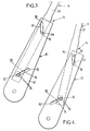
- les figures 3 et 4 sont des vues schématiques partielles de l'armature de dossier de la figure 2, respectivement dans les deux positions angulaires extrêmes de la partie supérieure de cette armature,
- la figure 5 est une vue en perspective partielle de l'armature du dossier appartenant au siège de la figure 1, selon une deuxième forme de réalisation de l'invention,
- les figures 6 et 7 sont des vues schématiques partielles de l'armature de la figure 5, respectivement dans les deux positions angulaires extrêmes de la partie supérieure de cette armature,
- la figure 8 est une vue schématique partielle de l'armature du dossier appartenant au siège de la figure 1, selon une troisième forme de réalisation de l'invention,
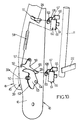
- la figure 9 est une vue de détail en coupe de l'armature de la figure 8, montrant le mécanisme de commande de cette armature,
- et la figure 10 est une vue en perspective partielle de l'armature du dossier appartenant au siège de la figure 1 selon une quatrième forme de réalisation de l'invention.
- un pivot inférieur 23 qui est engagé dans la rainure inférieure 14 correspondante et qui se trouve normalement à la première extrémité 15 de cette rainure,
- et un pivot supérieur 24 qui est engagé dans la rainure 17 correspondante.
- d'une part, la première position angulaire susmentionnée de l'armature 11, lorsque les doigts 31 se trouvent à la première extrémité 15 de la rainure 14 correspondante (figure 3),
- et d'autre part, la deuxième position angulaire susmentionnée de l'armature 11, lorsque les doigts 31 se trouvent à la deuxième extrémité 16 de la rainure 14 correspondante (figure 4).
- d'une part, la première extrémité 15 de ladite rainure 14, ce qui correspond à la première position angulaire susmentionnée de la partie supérieure 11 de l'armature du dossier (figure 6),
- et d'autre part, la deuxième extrémité 16 de la rainure 14, ce qui correspond à la deuxième position angulaire susmentionnée de la partie supérieure 11 de l'armature du dossier (figure 7).
- d'un pivot 24 supérieur coulissant dans une lumière oblique 17 orientée vers le haut et vers l'avant, comme dans la quatrième forme de réalisation,
- et d'un pivot 55 solidaire d'une biellette 56, elle-même reliée au flasque 12 par un pivot 57.
Claims (11)
- Siège de véhicule comportant un dossier (4) qui est surmonté d'un appui-tête (5) et qui est doté d'une armature rigide (9) supportant une matelassure (4a), ce dossier présentant une face avant (6) qui est destinée à servir d'appui pour le dos d'un passager, l'armature (9) du dossier étant formée en deux parties déplaçables l'une par rapport à l'autre, savoir d'une part, une partie inférieure (10) et, d'autre part, une partie supérieure (11) qui porte l'appui-tête (5), cette partie supérieure étant montée pivotante sur la partie inférieure autour d'un axe de rotation (X') entre des première et deuxième positions angulaires, respectivement inclinées au maximum vers l'arrière et au maximum vers l'avant par rapport à la partie inférieure (10), la face avant (6) du dossier présentant elle-même deux zones superposées inférieure (7) et supérieure (8) qui sont solidaires respectivement des parties inférieure (10) et supérieure (11) de l'armature du dossier, la partie supérieure (11) de l'armature du dossier présentant un organe d'appui (22) qui est disposé dans le dossier (4) au-dessous du niveau de l'axe de rotation (X') de ladite partie supérieure (11) pour que, lorsque le véhicule subit un choc arrière, le dos du passager appuie vers l'arrière sur ledit organe d'appui en s'enfonçant dans la matelassure (4a) du dossier, de façon à solliciter la partie supérieure (11) de l'armature du dossier vers sa deuxième position angulaire, les parties supérieure (11) et inférieure (10) de l'armature du dossier étant reliées entre elles par l'intermédiaire d'un dispositif de blocage (35;41) qui empêche normalement le pivotement involontaire de la partie supérieure (11), ce dispositif de blocage étant dimensionné pour céder lorsque la partie supérieure (11) du dossier n'est pas dans sa deuxième position angulaire et que ledit organe d'appui (22) subit une force dirigée vers l'arrière et supérieure à une valeur prédéterminée, en cas de choc arrière, et l'appui-tête (5) étant monté sur la partie supérieure (11) du dossier de façon à subir le même mouvement que ladite partie supérieure (11) en cas de choc arrière,
caractérisé en ce que le dispositif de blocage comprend un mécanisme de réglage (35;41) entraíné par un organe de commande (32;40), ce mécanisme de réglage étant adapté pour déplacer la partie supérieure (11) de l'armature du dossier entre ses première et deuxième positions angulaires en fonction de l'actionnement de l'organe de commande (32;40), et pour bloquer ladite partie supérieure de l'armature du dossier lorsque l'organe de commande n'est pas actionné, tant que ledit organe d'appui (22) ne subit pas une force dirigée vers l'arrière et supérieure à ladite valeur prédéterminée. - Siège selon la revendication 1, dans lequel la partie supérieure (11) de l'armature du dossier est montée sur la partie inférieure (10) pour se déplacer vers le haut en même temps qu'elle pivote vers l'avant.
- Siège selon l'une quelconque des revendications 1 et 2, dans lequel la partie supérieure (11) de l'armature du dossier se présente sous la forme d'un cadre qui comporte une traverse inférieure horizontale (22), laquelle traverse constitue ledit organe d'appui.
- Siège selon l'une quelconque des revendications précédentes, dans lequel le mécanisme de réglage comprend au moins un organe d'entraínement rotatif (31) en prise avec une denture (30), cet organe d'entraínement et cette denture étant reliés l'un à la partie supérieure (11) de l'armature du dossier et l'autre à la partie inférieure (10) de cette armature pour qu'un déplacement de l'organe d'entraínement (31) sur la denture (30) corresponde à une variation d'inclinaison de la partie supérieure (11) de l'armature du dossier, et la denture (30) étant adaptée pour se déformer progressivement plastiquement en permettant à l'organe d'entraínement (31) de se déplacer sans rotation le long de ladite denture en cas de choc arrière, cette denture constituant ainsi les moyens d'absorption d'énergie.
- Siège selon la revendication 4, dans lequel la partie supérieure (10) de l'armature du dossier est montée pivotante sur la partie inférieure (11) de cette armature au moyen de pivots (23,24) coulissant dans des glissières (14,17), au moins un de ces pivots (23) comprenant ledit organe d'entraínement (31), et ladite denture (30) étant formée dans la glissière (14) correspondante.
- Siège selon l'une quelconque des revendications 1 à 3, dans lequel la partie supérieure (11) de l'armature du dossier est montée pivotante sur la partie inférieure (10) de cette armature au moyen de pivots (23,24) coulissants dans des glissières (14,17), au moins un de ces pivots (23) étant solidarisé avec une bielle (36), ce pivot (23) et la glissière (14) correspondante étant solidaires l'une de la partie supérieure (11) de l'armature du dossier, et l'autre de la partie inférieure (10) de cette armature, la bielle (36) étant déplaçable au moyen dudit mécanisme de réglage (41) par rapport à la partie (10) de l'armature du dossier qui comprend ladite glissière, de façon qu'un déplacement de la bielle (36) entraíne un déplacement concomitant des pivots (23,24) dans leurs glissières (14,17), et la bielle (36) étant déformable plastiquement en cas de choc arrière en constituant ainsi les moyens d'absorption d'énergie.
- Siège selon la revendication 6, dans lequel le mécanisme de réglage (41) comprend un pignon (38) monté rotatif sur la partie (10) de l'armature du dossier qui comprend la glissière correspondant à la bielle, ce pignon étant en prise avec une crémaillère (37) formée dans la bielle (36).
- Siège selon l'une quelconque des revendications 6 et 7, dans lequel la bielle se présente sous la forme d'une plaque de tôle qui est pourvue d'une fente (42) s'étendant entre des première et deuxième extrémités (43,44), cette fente comportant une partie élargie à sa première extrémité et une partie resserrée (45) qui s'étend depuis ladite partie élargie jusqu'à la deuxième extrémité (44) de la fente, le pivot (23) qui est solidarisé avec la bielle (36) étant engagé sensiblement sans jeu dans ladite partie élargie, ladite fente (42) étant disposée sensiblement en correspondance avec la glissière (14) dans laquelle coulisse ledit pivot (23) au moins lorsque la partie supérieure (11) de l'armature du dossier est dans sa première position angulaire, et la fente (42) étant adaptée pour se déformer plastiquement progressivement en permettant audit pivot (23) de se déplacer vers la deuxième extrémité (44) de la fente lorsque la partie supérieure (11) de l'armature du dossier est déplacée vers sa deuxième position angulaire en cas de choc arrière.
- Siège selon l'une quelconque des revendications 1 à 3, dans lequel le mécanisme de réglage (41) est porté par la partie inférieure (10) de l'armature du dossier et entraíne un pignon (50) qui est en prise avec une bielle dentée (52) montée pivotante sur la partie inférieure (10) du dossier et articulée à la partie supérieure (11) du dossier, le mécanisme de réglage étant adapté pour laisser tourner le pignon (50) en le freinant en l'absence d'actionnement de l'organe de commande (40), lorsque ledit pignon (50) subit un couple de rotation supérieur à une valeur prédéterminée, en cas de choc arrière.
- Siège selon l'une quelconque des revendications 1 à 3, dans lequel le mécanisme de réglage entraíne un pignon (50) qui est monté sur la partie inférieure (10) de l'armature du dossier et qui entraíne une came dentée (63) elle-même montée pivotante sur ladite partie inférieure (10), cette came (63) présentant un bord d'appui (65) qui est en contact avec un élément (55) solidaire de la partie supérieure (11) de l'armature du dossier de façon à permettre uniquement un déplacement de ladite partie supérieure (11) vers sa deuxième position angulaire, et ladite partie supérieure (11) de l'armature du dossier étant sollicitée élastiquement vers sa première position angulaire.
- Siège selon la revendication 10, dans lequel l'élément (55) solidaire de la partie supérieure (11) de l'armature du dossier relie ladite partie supérieure (11) à une biellette (56) qui est montée pivotante sur la partie inférieure (10) de l'armature du dossier.
Applications Claiming Priority (3)
| Application Number | Priority Date | Filing Date | Title |
|---|---|---|---|
| FR9708435A FR2765533B1 (fr) | 1997-07-03 | 1997-07-03 | Siege de vehicule dote d'un dispositif de protection du cou en cas de choc arriere |
| FR9708435 | 1997-07-03 | ||
| EP98401626A EP0888926B1 (fr) | 1997-07-03 | 1998-06-30 | Siège de véhicule doté d'un dispositif de protection du cou en cas de choc arrière |
Related Parent Applications (1)
| Application Number | Title | Priority Date | Filing Date |
|---|---|---|---|
| EP98401626A Division EP0888926B1 (fr) | 1997-07-03 | 1998-06-30 | Siège de véhicule doté d'un dispositif de protection du cou en cas de choc arrière |
Publications (3)
| Publication Number | Publication Date |
|---|---|
| EP1092585A2 true EP1092585A2 (fr) | 2001-04-18 |
| EP1092585A3 EP1092585A3 (fr) | 2004-11-03 |
| EP1092585B1 EP1092585B1 (fr) | 2005-08-31 |
Family
ID=9508817
Family Applications (2)
| Application Number | Title | Priority Date | Filing Date |
|---|---|---|---|
| EP98401626A Expired - Lifetime EP0888926B1 (fr) | 1997-07-03 | 1998-06-30 | Siège de véhicule doté d'un dispositif de protection du cou en cas de choc arrière |
| EP01102204A Expired - Lifetime EP1092585B1 (fr) | 1997-07-03 | 1998-06-30 | Siège de véhicule doté d'un dispositif de protection du cou en cas de choc arrière |
Family Applications Before (1)
| Application Number | Title | Priority Date | Filing Date |
|---|---|---|---|
| EP98401626A Expired - Lifetime EP0888926B1 (fr) | 1997-07-03 | 1998-06-30 | Siège de véhicule doté d'un dispositif de protection du cou en cas de choc arrière |
Country Status (9)
| Country | Link |
|---|---|
| US (1) | US6024406A (fr) |
| EP (2) | EP0888926B1 (fr) |
| JP (2) | JPH1170828A (fr) |
| KR (1) | KR100337001B1 (fr) |
| AR (1) | AR013177A1 (fr) |
| BR (1) | BR9802346A (fr) |
| DE (2) | DE69831430T2 (fr) |
| ES (1) | ES2172096T3 (fr) |
| FR (1) | FR2765533B1 (fr) |
Cited By (2)
| Publication number | Priority date | Publication date | Assignee | Title |
|---|---|---|---|---|
| FR2898307A1 (fr) * | 2006-03-07 | 2007-09-14 | Faurecia Sieges Automobile | Siege de vehicule dote d'un equipage mobile monte sur une armature de support. |
| US8894144B2 (en) | 2004-09-27 | 2014-11-25 | Lear Corporation | Vehicle seat having active head restraint |
Families Citing this family (173)
| Publication number | Priority date | Publication date | Assignee | Title |
|---|---|---|---|---|
| GB2316442B (en) * | 1996-08-16 | 2000-02-23 | Autoliv Dev | Improvements in or relating to a seat back support mechanism |
| GB2347345B (en) * | 1996-09-06 | 2000-10-18 | Autoliv Dev | Improvements in or relating to a safety seat |
| DE19831218C2 (de) * | 1998-07-02 | 2003-02-06 | Brose Fahrzeugteile | Fahrzeugsitz mit einer Rückenlehne, an der eine Kopfstütze höhenverstellbar geführt ist |
| EP0995631B1 (fr) * | 1998-08-28 | 2004-10-27 | Ikeda Bussan Co., Ltd. | Dossier de siège pour automobile |
| WO2000035707A1 (fr) | 1998-12-14 | 2000-06-22 | Lear Corporation | Appui-tete pivotant pour vehicules |
| US6523892B1 (en) * | 1999-05-20 | 2003-02-25 | Mazda Motor Corporation | Seat structure for vehicle |
| IT1306152B1 (it) * | 1999-06-02 | 2001-05-30 | Aviointeriors Spa | Poltrona con movimento a culla perfezionato, in particolare peraeromobili. |
| JP3760979B2 (ja) * | 1999-09-17 | 2006-03-29 | マツダ株式会社 | 車両用シート装置 |
| DE29918761U1 (de) | 1999-10-25 | 2000-01-20 | Fehrer F S Gmbh & Co Kg | Kopfstützenanordnung für einen Fahrzeugsitz |
| DE19951820A1 (de) * | 1999-10-27 | 2001-05-03 | Hammerstein Gmbh C Rob | Fahrzeugsitz für ein Kraftfahrzeug mit einer Rückenlehne |
| DE10001329B4 (de) * | 2000-10-05 | 2004-07-08 | Faurecia Autositze Gmbh & Co. Kg | Rückenlehne eines Kraftfahrzeugsitzes |
| DE10001326C1 (de) * | 2000-01-14 | 2001-08-16 | Faurecia Autositze Gmbh & Co | Rückenlehne eines Kraftfahrzeugsitzes |
| JP4152061B2 (ja) * | 2000-05-15 | 2008-09-17 | 日産自動車株式会社 | 乗物用乗員拘束装置 |
| US6416125B1 (en) | 2000-05-23 | 2002-07-09 | Lear Corporation | Vehicle seat connection assembly |
| JP3467568B2 (ja) * | 2000-09-25 | 2003-11-17 | 日本発条株式会社 | 車両用シートバックフレーム |
| DE10051344C1 (de) * | 2000-10-16 | 2001-11-29 | Faurecia Autositze Gmbh & Co | Rückenlehne eines Kraftfahrzeugsitzes mit einer Kopfstütze |
| DE10060764C1 (de) * | 2000-12-07 | 2002-01-17 | Faurecia Autositze Gmbh & Co | Kraftfahrzeugsitz |
| DE60201884T2 (de) * | 2001-01-23 | 2005-11-03 | Autoliv Development Ab | Fahrzeugsitz |
| US6719368B1 (en) | 2001-02-28 | 2004-04-13 | Magna Seating Systems Inc. | Vehicle seat assembly having a cradle seat back |
| DE10113091B4 (de) * | 2001-03-17 | 2006-01-12 | Faurecia Autositze Gmbh & Co. Kg | Kraftfahrzeugsitz mit einer crashaktiven Kopfstütze |
| DE10127633C1 (de) * | 2001-06-07 | 2002-09-12 | Faurecia Autositze Gmbh & Co | Kraftfahrzeugsitz |
| US6631955B2 (en) * | 2001-06-29 | 2003-10-14 | Lear Corporation | Variable movement headrest arrangement |
| GB2377370B (en) * | 2001-07-10 | 2005-03-23 | Autoliv Dev | Improvements in or relating to a head-rest arrangement |
| DE10139763B4 (de) * | 2001-08-13 | 2004-11-04 | Faurecia Autositze Gmbh & Co. Kg | Kraftfahrzeugsitz |
| JP2005502520A (ja) | 2001-09-10 | 2005-01-27 | ジョンソン・コントロールズ・ゲー・エム・ベー・ハー | 車輌シートのバックレスト |
| FR2830219B1 (fr) * | 2001-10-01 | 2003-12-05 | Faurecia Sieges Automobile | Siege de vehicule dote d'un dispositif de securite mobile |
| ES2192476B2 (es) * | 2002-01-18 | 2004-06-01 | Sebastian Aramburu Echevarria | Sillon reclinable. |
| JP4014938B2 (ja) * | 2002-06-06 | 2007-11-28 | 本田技研工業株式会社 | 車両用乗員保護装置 |
| JP4133059B2 (ja) * | 2002-07-18 | 2008-08-13 | 日本発条株式会社 | 前方可動式ヘッドレストを有する車両用シート |
| KR100461104B1 (ko) * | 2002-08-08 | 2004-12-13 | 현대자동차주식회사 | 자동차용 프론트시트의 리클라이너 잠금장치 |
| FR2843343B1 (fr) | 2002-08-12 | 2005-04-01 | Renault Sa | Appuie-tete actif pour siege de vehicule roulant |
| FR2844489B1 (fr) | 2002-09-16 | 2005-06-10 | Faurecia Sieges Automobile | Siege de vehicule dote d'un dispositif de protection du cou en cas de choc arriere |
| DE10246475B4 (de) * | 2002-09-27 | 2006-10-19 | Brose Fahrzeugteile Gmbh & Co. Kommanditgesellschaft, Coburg | Kopfstützenanordnung für einen Kraftfahrzeugsitz |
| US6709053B1 (en) * | 2002-09-30 | 2004-03-23 | Lear Corporation | Vehicle seat assembly with energy managing member |
| KR100461147B1 (ko) * | 2002-10-12 | 2004-12-14 | 현대자동차주식회사 | 목 상해 방지용 자동차 시트 |
| GB2395114B (en) * | 2002-11-08 | 2005-04-13 | Autoliv Dev | Improvements in or relating to a head-rest arrangement |
| KR20040042388A (ko) * | 2002-11-14 | 2004-05-20 | 현대자동차주식회사 | 차량용 시트백 프레임 구조 |
| US7134716B2 (en) * | 2002-11-27 | 2006-11-14 | Lear Corporation | Headrest seat-back arrangement |
| US6789846B2 (en) | 2002-12-20 | 2004-09-14 | Lear Corporation | Vehicle seat having a movable head restraint |
| FR2849812B1 (fr) | 2003-01-14 | 2006-02-17 | Faurecia Sieges Automobile | Siege de vehicule protegeant un utilisateur contre les effets d'un choc arriere |
| US7097242B2 (en) * | 2003-02-06 | 2006-08-29 | Lear Corporation | Anti-backdriving active head restraint |
| US6840560B2 (en) * | 2003-02-18 | 2005-01-11 | Ford Global Technologies, Llc | Vehicular seat assembly having a movable headrest and a vehicle which incorporates the vehicular seat assembly |
| KR20040104993A (ko) * | 2003-06-03 | 2004-12-14 | 현대자동차주식회사 | 액티브 헤드레스트 |
| GB2403137B (en) | 2003-06-24 | 2006-03-08 | Autoliv Dev | Improvements in or relating to a vehicle seat |
| US6749256B1 (en) | 2003-09-08 | 2004-06-15 | Lear Corporation | Vehicle seat having a movable head restraint |
| JP4348255B2 (ja) * | 2003-10-08 | 2009-10-21 | デルタ工業株式会社 | 車両用シート |
| DE10355819B4 (de) | 2003-11-28 | 2008-08-21 | Keiper Gmbh & Co.Kg | Fahrzeugsitz, insbesondere Kraftfahrzeugsitz |
| JP2005186670A (ja) * | 2003-12-24 | 2005-07-14 | Delta Kogyo Co Ltd | 車両用シート |
| US20050156456A1 (en) * | 2004-01-16 | 2005-07-21 | Robinson David L. | Vehicle seat headrest adjustment apparatus |
| US6880890B1 (en) | 2004-02-05 | 2005-04-19 | Fisher Dynamics Corporation | Multi-position headrest for vehicle seat |
| US7055901B2 (en) * | 2004-02-26 | 2006-06-06 | International Truck Intellectual Property Company, Llc | School bus passenger seat with integrated restraints |
| FR2867725B1 (fr) * | 2004-03-16 | 2007-06-15 | Faurecia Sieges Automobile | Siege de vehicule automobile dote d'un dispositif de protection du cou en cas de choc arriere |
| DE102004016474B3 (de) | 2004-03-31 | 2005-08-11 | Johnson Controls Gmbh | Kopfstütze, insbesondere für ein Kraftfahrzeug |
| JP4815111B2 (ja) * | 2004-08-19 | 2011-11-16 | 日本発條株式会社 | 車両用シート |
| JP2006087556A (ja) * | 2004-09-22 | 2006-04-06 | T S Tec Kk | ヘッドレスト |
| US7044544B2 (en) * | 2004-09-27 | 2006-05-16 | Lear Corporation | Vehicle seat assembly having active head restraint system |
| GB2418843B (en) * | 2004-10-11 | 2008-07-16 | Autoliv Dev | Improvements in or relating to a recliner mechanism |
| GB2421277B (en) * | 2004-12-20 | 2009-10-14 | Autoliv Dev | Improvements in or relating to a seat back support mechanism |
| US7185950B2 (en) * | 2004-12-28 | 2007-03-06 | Fisher Dynamics Corporation | Head restraint system |
| US20060138817A1 (en) * | 2004-12-29 | 2006-06-29 | Gorman Patrick J | Energy absorbing seat recliner assembly |
| JP4860932B2 (ja) * | 2005-02-04 | 2012-01-25 | テイ・エス テック株式会社 | 衝撃吸収可能な自動車用シート |
| US20060226686A1 (en) * | 2005-03-22 | 2006-10-12 | Shihong Yu | Spinal protection system for automotive seat |
| JP4721334B2 (ja) * | 2005-06-17 | 2011-07-13 | テイ・エス テック株式会社 | 車両用シート |
| KR100776917B1 (ko) * | 2006-03-09 | 2007-11-15 | 다이모스(주) | 자동차 시트의 목 상해 방지장치 |
| JP4643480B2 (ja) * | 2006-03-23 | 2011-03-02 | トヨタ自動車株式会社 | 車両用シートバックフレーム |
| JP4151984B2 (ja) * | 2006-07-13 | 2008-09-17 | 株式会社タチエス | 車両用シートのシートバック構造 |
| US20080030061A1 (en) * | 2006-08-04 | 2008-02-07 | Srinivas Pejathaya | Multi-position adjustment mechanism |
| JP4900926B2 (ja) * | 2006-08-29 | 2012-03-21 | 株式会社タチエス | 車両用シートのシートバック構造 |
| US7530633B2 (en) * | 2006-10-17 | 2009-05-12 | Tachi-S Co., Ltd. | Seat back structure of vehicle seat |
| US7677659B2 (en) * | 2007-02-06 | 2010-03-16 | Lear Corporation | Active head restraint systems for vehicle seats |
| US7441838B2 (en) * | 2007-02-22 | 2008-10-28 | Lear Corporation | Back support mechanism for vehicle seat |
| DE102007018715A1 (de) * | 2007-04-20 | 2008-10-23 | Faurecia Autositze Gmbh | Fahrzeugsitz |
| WO2009001491A1 (fr) * | 2007-06-27 | 2008-12-31 | Toyota Boshoku Kabushiki Kaisha | Mécanisme d'embrayage |
| US7850235B2 (en) * | 2007-10-17 | 2010-12-14 | Lear Corporation | Active head restraint system with actuating system for a vehicle seat |
| KR100992540B1 (ko) * | 2007-12-14 | 2010-11-08 | 현대자동차주식회사 | 차량용 폴딩 헤드레스트 장치 |
| JP5181790B2 (ja) * | 2008-04-02 | 2013-04-10 | トヨタ紡織株式会社 | ヘッドレスト作動装置 |
| FR2931403B1 (fr) * | 2008-05-22 | 2010-04-23 | Sicma Aero Seat | Dispositif d'absorption de choc et siege comportant un tel dispositif |
| US8205941B2 (en) * | 2008-07-30 | 2012-06-26 | Trw Vehicle Safety Systems Inc. | Active head restraint for a vehicle seat |
| WO2010050963A1 (fr) * | 2008-10-31 | 2010-05-06 | Lear Corporation | Ensemble appui-tête |
| US8226163B1 (en) * | 2009-02-06 | 2012-07-24 | Goodrich Corporation | Aircraft divan |
| DE102009008736A1 (de) * | 2009-02-12 | 2010-09-09 | Lear Corp., Southfield | Fahrzeugsitzanordnung mit bequemem Rückenlehnenabschnitt |
| FR2943957B1 (fr) * | 2009-04-02 | 2012-12-21 | Faurecia Sieges Automobile | Siege de vehicule automobile a deplacement controle du dossier en cas de choc arriere |
| JP5654273B2 (ja) * | 2009-09-04 | 2015-01-14 | デルタ工業株式会社 | 車両用シートバックフレームの構造 |
| JP5593680B2 (ja) | 2009-11-12 | 2014-09-24 | マツダ株式会社 | 車両用シート装置 |
| JP5550972B2 (ja) * | 2010-04-14 | 2014-07-16 | 株式会社タチエス | シートバックのフレーム構造体 |
| JP5685026B2 (ja) * | 2010-07-30 | 2015-03-18 | 日本テクニカ株式会社 | ヘッドレストブラケットの支持構造 |
| EP2616272B1 (fr) | 2010-09-14 | 2017-06-21 | Basf Se | Support à absorption d'énergie destiné au siège d'un véhicule |
| CN102085817B (zh) * | 2011-01-20 | 2012-10-10 | 浙江吉利汽车研究院有限公司 | 一种可调节的汽车座椅结构 |
| DE102012108352A1 (de) * | 2012-09-07 | 2014-03-13 | Recaro Aircraft Seating Gmbh & Co. Kg | Sitzenergieabsorptionsvorrichtung |
| FR2995264B1 (fr) * | 2012-09-11 | 2015-05-15 | Renault Sa | Siege de vehicule dote d'un dossier securise |
| US9126504B2 (en) | 2013-01-24 | 2015-09-08 | Ford Global Technologies, Llc | Integrated thin flex composite headrest assembly |
| US9902293B2 (en) | 2013-01-24 | 2018-02-27 | Ford Global Technologies, Llc | Independent cushion extension with optimized leg-splay angle |
| US9216677B2 (en) | 2013-01-24 | 2015-12-22 | Ford Global Technologies, Llc | Quick-connect trim carrier attachment |
| US9096157B2 (en) | 2013-01-24 | 2015-08-04 | Ford Global Technologies, Llc | Seating assembly with air distribution system |
| US9016783B2 (en) | 2013-01-24 | 2015-04-28 | Ford Global Technologies, Llc | Thin seat flex rest composite cushion extension |
| US9409504B2 (en) | 2013-01-24 | 2016-08-09 | Ford Global Technologies, Llc | Flexible seatback system |
| US9415713B2 (en) | 2013-01-24 | 2016-08-16 | Ford Global Technologies, Llc | Flexible seatback system |
| US8727374B1 (en) | 2013-01-24 | 2014-05-20 | Ford Global Technologies, Llc | Vehicle seatback with side airbag deployment |
| US9126508B2 (en) | 2013-01-24 | 2015-09-08 | Ford Global Technologies, Llc | Upper seatback pivot system |
| US9399418B2 (en) | 2013-01-24 | 2016-07-26 | Ford Global Technologies, Llc | Independent cushion extension and thigh support |
| US9061616B2 (en) | 2013-01-24 | 2015-06-23 | Ford Global Technologies, Llc | Articulating headrest assembly |
| US9016784B2 (en) | 2013-01-24 | 2015-04-28 | Ford Global Technologies, Llc | Thin seat leg support system and suspension |
| US9193284B2 (en) | 2013-06-11 | 2015-11-24 | Ford Global Technologies, Llc | Articulating cushion bolster for ingress/egress |
| US9527418B2 (en) | 2013-09-12 | 2016-12-27 | Ford Global Technologies, Llc | Semi rigid push/pull vented envelope system |
| US8905431B1 (en) | 2013-09-24 | 2014-12-09 | Ford Global Technologies, Llc | Side airbag assembly for a vehicle seat |
| US9187019B2 (en) | 2013-10-17 | 2015-11-17 | Ford Global Technologies, Llc | Thigh support for customer accommodation seat |
| US9505322B2 (en) | 2013-10-25 | 2016-11-29 | Ford Global Technologies, Llc | Manual lumbar pump assembly |
| US9315130B2 (en) | 2013-11-11 | 2016-04-19 | Ford Global Technologies, Llc | Articulating head restraint |
| US9566884B2 (en) | 2013-11-11 | 2017-02-14 | Ford Global Technologies, Llc | Powered head restraint electrical connector |
| US9365143B2 (en) | 2013-12-12 | 2016-06-14 | Ford Global Technologies, Llc | Rear seat modular cushion |
| US9315131B2 (en) | 2014-01-23 | 2016-04-19 | Ford Global Technologies, Llc | Suspension seat back and cushion system having an inner suspension panel |
| US9649963B2 (en) | 2014-03-04 | 2017-05-16 | Ford Global Technologies, Pllc | Trim and foam assembly for a vehicle seat |
| DE102014206983B4 (de) * | 2014-03-14 | 2020-06-10 | Adient Luxembourg Holding S.À R.L. | Fahrzeugsitz und Verfahren zur Energieabsorption bei Unfällen |
| US9527419B2 (en) | 2014-03-31 | 2016-12-27 | Ford Global Technologies, Llc | Vehicle seating assembly with manual cushion tilt |
| US9421894B2 (en) | 2014-04-02 | 2016-08-23 | Ford Global Technologies, Llc | Vehicle seating assembly with manual independent thigh supports |
| US9302643B2 (en) | 2014-04-02 | 2016-04-05 | Ford Global Technologies, Llc | Vehicle seating assembly with side airbag deployment |
| US9694741B2 (en) | 2014-08-25 | 2017-07-04 | Ford Global Technologies, Llc | Ambient functional lighting of a seat |
| US10471874B2 (en) | 2014-09-02 | 2019-11-12 | Ford Global Technologies, Llc | Massage bladder matrix |
| US9333882B2 (en) | 2014-10-03 | 2016-05-10 | Ford Global Technologies, Llc | Manual upper seatback support |
| US9789790B2 (en) | 2014-10-03 | 2017-10-17 | Ford Global Technologies, Llc | Tuned flexible support member and flexible suspension features for comfort carriers |
| US9776533B2 (en) | 2014-10-03 | 2017-10-03 | Ford Global Technologies, Llc | Torsion bar upper seatback support assembly |
| US9771003B2 (en) | 2014-10-29 | 2017-09-26 | Ford Global Technologies, Llc | Apparatus for customizing a vehicle seat for an occupant |
| US9517777B2 (en) | 2014-11-06 | 2016-12-13 | Ford Global Technologies, Llc | Lane departure feedback system |
| US9340131B1 (en) | 2014-11-06 | 2016-05-17 | Ford Global Technologies, Llc | Head restraint with a multi-cell bladder assembly |
| WO2016079713A1 (fr) * | 2014-11-19 | 2016-05-26 | Zodiac Seats France | Cinématique de siège de pilote de confort |
| US10065570B2 (en) | 2014-12-10 | 2018-09-04 | Ford Global Technologies, Llc | Electronic device holder for a vehicle seat |
| US9593642B2 (en) | 2014-12-19 | 2017-03-14 | Ford Global Technologies, Llc | Composite cam carrier |
| US9663000B2 (en) | 2015-01-16 | 2017-05-30 | Ford Global Technologies, Llc | Vehicle seat configured to improve access |
| US9707877B2 (en) | 2015-01-20 | 2017-07-18 | Ford Global Technologies, Llc | Independent thigh extension and support trim carrier |
| US9365142B1 (en) | 2015-01-20 | 2016-06-14 | Ford Global Technologies, Llc | Manual independent thigh extensions |
| US9566930B2 (en) | 2015-03-02 | 2017-02-14 | Ford Global Technologies, Llc | Vehicle seat assembly with side-impact airbag deployment mechanism |
| US9802535B2 (en) | 2015-04-27 | 2017-10-31 | Ford Global Technologies, Llc | Seat having ambient lighting |
| US10046682B2 (en) | 2015-08-03 | 2018-08-14 | Ford Global Technologies, Llc | Back cushion module for a vehicle seating assembly |
| US9718387B2 (en) | 2015-08-03 | 2017-08-01 | Ford Global Technologies, Llc | Seat cushion module for a vehicle seating assembly |
| US9688174B2 (en) | 2015-08-07 | 2017-06-27 | Ford Global Technologies, Llc | Multi-cell seat cushion assembly |
| US9573528B1 (en) | 2015-08-25 | 2017-02-21 | Ford Global Technologies, Llc | Integrated seatback storage |
| US9616776B1 (en) | 2015-11-16 | 2017-04-11 | Ford Global Technologies, Llc | Integrated power thigh extender |
| JP6555102B2 (ja) * | 2015-11-20 | 2019-08-07 | テイ・エス テック株式会社 | 乗物用シート |
| US9809131B2 (en) | 2015-12-04 | 2017-11-07 | Ford Global Technologies, Llc | Anthropomorphic pivotable upper seatback support |
| US9931999B2 (en) | 2015-12-17 | 2018-04-03 | Ford Global Technologies, Llc | Back panel lower clip anchorage features for dynamic events |
| US10093214B2 (en) | 2016-01-14 | 2018-10-09 | Ford Global Technologies, Llc | Mechanical manual leg tilt |
| US9914421B2 (en) | 2016-01-15 | 2018-03-13 | Ford Global Technologies, Llc | Seatback flexible slip plane joint for side air bag deployment |
| US9756408B2 (en) | 2016-01-25 | 2017-09-05 | Ford Global Technologies, Llc | Integrated sound system |
| US10052990B2 (en) | 2016-01-25 | 2018-08-21 | Ford Global Technologies, Llc | Extended seatback module head restraint attachment |
| US10035442B2 (en) | 2016-01-25 | 2018-07-31 | Ford Global Technologies, Llc | Adjustable upper seatback module |
| US9776543B2 (en) | 2016-01-25 | 2017-10-03 | Ford Global Technologies, Llc | Integrated independent thigh supports |
| US10286818B2 (en) | 2016-03-16 | 2019-05-14 | Ford Global Technologies, Llc | Dual suspension seating assembly |
| US10046681B2 (en) | 2016-04-12 | 2018-08-14 | Ford Global Technologies, Llc | Articulating mechanical thigh extension composite trim payout linkage system |
| US9849817B2 (en) | 2016-03-16 | 2017-12-26 | Ford Global Technologies, Llc | Composite seat structure |
| US9994135B2 (en) | 2016-03-30 | 2018-06-12 | Ford Global Technologies, Llc | Independent cushion thigh support |
| US10220737B2 (en) | 2016-04-01 | 2019-03-05 | Ford Global Technologies, Llc | Kinematic back panel |
| US9889773B2 (en) | 2016-04-04 | 2018-02-13 | Ford Global Technologies, Llc | Anthropomorphic upper seatback |
| US9802512B1 (en) | 2016-04-12 | 2017-10-31 | Ford Global Technologies, Llc | Torsion spring bushing |
| US10081279B2 (en) | 2016-04-12 | 2018-09-25 | Ford Global Technologies, Llc | Articulating thigh extension trim tensioning slider mechanism |
| US10625646B2 (en) | 2016-04-12 | 2020-04-21 | Ford Global Technologies, Llc | Articulating mechanical thigh extension composite trim payout linkage system |
| US9845029B1 (en) | 2016-06-06 | 2017-12-19 | Ford Global Technologies, Llc | Passive conformal seat with hybrid air/liquid cells |
| US9834166B1 (en) | 2016-06-07 | 2017-12-05 | Ford Global Technologies, Llc | Side airbag energy management system |
| US9849856B1 (en) | 2016-06-07 | 2017-12-26 | Ford Global Technologies, Llc | Side airbag energy management system |
| US10166895B2 (en) | 2016-06-09 | 2019-01-01 | Ford Global Technologies, Llc | Seatback comfort carrier |
| US10377279B2 (en) | 2016-06-09 | 2019-08-13 | Ford Global Technologies, Llc | Integrated decking arm support feature |
| US10286824B2 (en) | 2016-08-24 | 2019-05-14 | Ford Global Technologies, Llc | Spreader plate load distribution |
| US10279714B2 (en) | 2016-08-26 | 2019-05-07 | Ford Global Technologies, Llc | Seating assembly with climate control features |
| US10239431B2 (en) | 2016-09-02 | 2019-03-26 | Ford Global Technologies, Llc | Cross-tube attachment hook features for modular assembly and support |
| US10391910B2 (en) | 2016-09-02 | 2019-08-27 | Ford Global Technologies, Llc | Modular assembly cross-tube attachment tab designs and functions |
| US9914378B1 (en) | 2016-12-16 | 2018-03-13 | Ford Global Technologies, Llc | Decorative and functional upper seatback closeout assembly |
| FR3062610B1 (fr) * | 2017-02-08 | 2019-04-19 | Expliseat | Siege pour vehicule avec dossier basculant |
| US10596936B2 (en) | 2017-05-04 | 2020-03-24 | Ford Global Technologies, Llc | Self-retaining elastic strap for vent blower attachment to a back carrier |
| DE102018101706A1 (de) * | 2018-01-25 | 2019-07-25 | Faurecia Autositze Gmbh | Fahrzeugsitz |
| DE102018222808B4 (de) * | 2018-09-21 | 2023-05-17 | Adient Us Llc | Träger für eine Kopfstütze und Kopfstütze |
| US11279488B2 (en) * | 2020-02-20 | 2022-03-22 | B/E Aerospace, Inc. | Seat assembly with sacrificial backrest breakover feature |
| FR3110117B1 (fr) | 2020-05-12 | 2022-06-10 | Faurecia Sieges Dautomobile | Siège pour véhicule automobile muni d’une interface de contrôle d’un mouvement d’une articulation du siège |
| JP7575045B2 (ja) * | 2020-10-28 | 2024-10-29 | 備前発条株式会社 | ヘッドレスト |
| US11833937B2 (en) | 2021-09-08 | 2023-12-05 | Faurecia Automotive Seating, Llc | Occupant support |
Citations (5)
| Publication number | Priority date | Publication date | Assignee | Title |
|---|---|---|---|---|
| US1529248A (en) | 1924-03-26 | 1925-03-10 | W G Nagel Electric Company | Automatic clutch |
| FR843668A (fr) | 1938-03-15 | 1939-07-07 | Dispositif de réglage angulaire et ses applications | |
| DE3734363A1 (de) | 1987-10-10 | 1989-04-20 | Burger Soehne | Vorrichtung zum verstellen eines kraftfahrzeugsitzes |
| US5593210A (en) | 1994-05-24 | 1997-01-14 | Schwarzbich; Joerg | Adjusting mechanism for a vehicle seat back |
| WO1997010117A1 (fr) | 1995-09-14 | 1997-03-20 | Autoliv Development Ab | Siege pour vehicule |
Family Cites Families (19)
| Publication number | Priority date | Publication date | Assignee | Title |
|---|---|---|---|---|
| US3578376A (en) * | 1968-09-20 | 1971-05-11 | Toyota Motor Co Ltd | Seat construction of a vehicle |
| US3802737A (en) * | 1972-07-07 | 1974-04-09 | Heizer K | Safety seat, particularly for automotive vehicles |
| US3998291A (en) * | 1975-08-06 | 1976-12-21 | Edwin George Davis | Automotive safety seat |
| FR2602133B1 (fr) * | 1986-08-01 | 1988-10-21 | Boulay Maurice | Siege dynamique dont l'inclinaison du dossier et de l'appui-tete varie en fonction des accelerations et decelerations du vehicule |
| FR2590529B1 (fr) * | 1985-11-22 | 1988-06-10 | Boulay Maurice | Fauteuil dynamique dont l'inclinaison du dossier et de l'appui-tete varie en fonction des accelerations et des decelerations du vehicule |
| EP0249605A1 (fr) * | 1985-11-22 | 1987-12-23 | BOULAY, Maurice | Siege dynamique dont l'inclinaison du dossier et de l'appui-tete varie en fonction des accelerations et des decelerations du vehicule |
| DE4020057C2 (de) * | 1990-06-23 | 1996-05-09 | Bayer Ag | Fahrzeugsitz |
| ES2029783T1 (es) * | 1990-08-31 | 1992-10-01 | Trw Repa Gmbh | Fijacion de un herraje de anclaje giratorio a la altura de la zona de la cabeza de un ocupante de un vehiculo. |
| US5366269A (en) * | 1992-08-20 | 1994-11-22 | Life Force Associates, L.P. | Apparatus for restraining a passenger in a vehicle |
| US5437494A (en) * | 1992-10-29 | 1995-08-01 | Life Force Associates, L.P. | Rearward moving seat |
| US5378043A (en) * | 1993-06-01 | 1995-01-03 | General Motors Corporation | Vehicle pivotal headrest |
| US5462332A (en) * | 1994-10-03 | 1995-10-31 | General Motors Corporation | High strength vehicle recliner seat |
| US5509716A (en) * | 1994-11-08 | 1996-04-23 | General Motors Corporation | Vehicle seat with perimeter frame and pelvic catcher |
| FR2736312B1 (fr) * | 1995-07-03 | 1997-09-19 | Faure Bertrand Equipements Sa | Armature de dossier pour siege de vehicule et siege comportant une telle armature de dossier |
| US5676421A (en) * | 1996-06-20 | 1997-10-14 | Lear Corporation | Vehicle seat energy absorbing mechanism |
| GB2318045B (en) * | 1996-10-09 | 2000-08-09 | Delphi Automotive Systems Gmbh | Vehicle seat and headrest arrangement |
| US5738407A (en) * | 1997-01-14 | 1998-04-14 | Lear Corporation | Head restraint airbag assembly |
| US5772280A (en) * | 1997-05-08 | 1998-06-30 | Lear Corporation | Dynamic actuation system for an articulated headrest portion of an automotive seat |
| US5927804A (en) * | 1998-02-11 | 1999-07-27 | Trw Inc. | Vehicle occupant protection apparatus |
-
1997
- 1997-07-03 FR FR9708435A patent/FR2765533B1/fr not_active Expired - Fee Related
-
1998
- 1998-06-30 EP EP98401626A patent/EP0888926B1/fr not_active Expired - Lifetime
- 1998-06-30 DE DE69831430T patent/DE69831430T2/de not_active Expired - Fee Related
- 1998-06-30 ES ES98401626T patent/ES2172096T3/es not_active Expired - Lifetime
- 1998-06-30 DE DE69803815T patent/DE69803815T2/de not_active Expired - Fee Related
- 1998-06-30 EP EP01102204A patent/EP1092585B1/fr not_active Expired - Lifetime
- 1998-07-01 US US09/108,280 patent/US6024406A/en not_active Expired - Fee Related
- 1998-07-02 BR BR9802346-2A patent/BR9802346A/pt not_active IP Right Cessation
- 1998-07-03 JP JP10189055A patent/JPH1170828A/ja active Pending
- 1998-07-03 KR KR1019980026901A patent/KR100337001B1/ko not_active Expired - Fee Related
- 1998-07-03 AR ARP980103262A patent/AR013177A1/es unknown
-
2001
- 2001-06-05 JP JP2001169366A patent/JP2002012073A/ja active Pending
Patent Citations (5)
| Publication number | Priority date | Publication date | Assignee | Title |
|---|---|---|---|---|
| US1529248A (en) | 1924-03-26 | 1925-03-10 | W G Nagel Electric Company | Automatic clutch |
| FR843668A (fr) | 1938-03-15 | 1939-07-07 | Dispositif de réglage angulaire et ses applications | |
| DE3734363A1 (de) | 1987-10-10 | 1989-04-20 | Burger Soehne | Vorrichtung zum verstellen eines kraftfahrzeugsitzes |
| US5593210A (en) | 1994-05-24 | 1997-01-14 | Schwarzbich; Joerg | Adjusting mechanism for a vehicle seat back |
| WO1997010117A1 (fr) | 1995-09-14 | 1997-03-20 | Autoliv Development Ab | Siege pour vehicule |
Cited By (2)
| Publication number | Priority date | Publication date | Assignee | Title |
|---|---|---|---|---|
| US8894144B2 (en) | 2004-09-27 | 2014-11-25 | Lear Corporation | Vehicle seat having active head restraint |
| FR2898307A1 (fr) * | 2006-03-07 | 2007-09-14 | Faurecia Sieges Automobile | Siege de vehicule dote d'un equipage mobile monte sur une armature de support. |
Also Published As
| Publication number | Publication date |
|---|---|
| EP0888926B1 (fr) | 2002-02-13 |
| US6024406A (en) | 2000-02-15 |
| DE69803815D1 (de) | 2002-03-21 |
| JPH1170828A (ja) | 1999-03-16 |
| KR19990013600A (ko) | 1999-02-25 |
| FR2765533A1 (fr) | 1999-01-08 |
| EP0888926A1 (fr) | 1999-01-07 |
| DE69831430T2 (de) | 2006-06-29 |
| DE69803815T2 (de) | 2002-09-19 |
| EP1092585B1 (fr) | 2005-08-31 |
| KR100337001B1 (ko) | 2002-08-22 |
| ES2172096T3 (es) | 2002-09-16 |
| JP2002012073A (ja) | 2002-01-15 |
| EP1092585A3 (fr) | 2004-11-03 |
| FR2765533B1 (fr) | 1999-09-03 |
| DE69831430D1 (de) | 2005-10-06 |
| AR013177A1 (es) | 2000-12-13 |
| BR9802346A (pt) | 1999-10-13 |
Similar Documents
| Publication | Publication Date | Title |
|---|---|---|
| EP1092585B1 (fr) | Siège de véhicule doté d'un dispositif de protection du cou en cas de choc arrière | |
| EP0756962B1 (fr) | Armature de dossier pour siège de véhicule | |
| CA2298342C (fr) | Mecanisme d'articulation pour siege de vehicule et siege equipe d'un tel mecanisme | |
| EP0755860B1 (fr) | Siège transformable en couchette pour aéronef | |
| FR2606337A1 (fr) | Dispositif de reglage d'inclinaison, notamment pour siege de vehicule automobile | |
| FR2851211A1 (fr) | Siege rabattable et vehicule comportant un tel siege | |
| FR2820696A1 (fr) | Siege de vehicule dote d'un dossier rabattable | |
| EP0537057B1 (fr) | Glissière pour siège de véhicule à position de retour fixe | |
| FR2841838A1 (fr) | Siege de vehicule equipe d'un mecanisme d'articulation | |
| FR2737868A1 (fr) | Siege de vehicule presentant une assise reglable en hauteur | |
| FR2832961A1 (fr) | Siege de vehicule | |
| FR2857305A1 (fr) | Siege de vehicule automobile a dossier articule comportant des moyens de blocage du dossier en cas de choc frontal | |
| EP0800952A1 (fr) | Siège de véhicule, déplaçable vers l'avant pour accéder à un espace arrière | |
| EP0522939B1 (fr) | Vérin monogalet permettant le verrouillage de deux éléments articulés entre eux | |
| FR2824796A1 (fr) | Dispositif pour fixer un long mecanisme de glissieres a un vehicule | |
| EP3436314A1 (fr) | Structure d'assise réglable d'un siège de véhicule comportant un brin boucle de ceinture de sécurité | |
| FR2750185A1 (fr) | Mecanisme pour commander un organe de sortie rotatif au moyen d'un poignee, et siege comportant un tel mecanisme | |
| FR2564045A1 (fr) | Appui-tete pivotant perfectionne | |
| FR2766430A1 (fr) | Siege ergonomique pour vehicule | |
| CA2330446C (fr) | Mecanisme d'articulation pour siege de vehicule et siege equipe d'un tel mecanisme | |
| FR2801850A1 (fr) | Mecanisme d'articulation pour siege de vehicule et siege equipe d'un tel mecanisme | |
| FR2832960A1 (fr) | Siege de vehicule | |
| EP2184202B1 (fr) | Siège pour un véhicule automobile | |
| EP4477465A1 (fr) | Véhicule comprenant un siège arrière doté d'un dossier orientable suivant au moins quatre positions | |
| FR3160656A1 (fr) | Dispositif d’accrochage de boucle de ceinture de sécurité |
Legal Events
| Date | Code | Title | Description |
|---|---|---|---|
| PUAI | Public reference made under article 153(3) epc to a published international application that has entered the european phase |
Free format text: ORIGINAL CODE: 0009012 |
|
| 17P | Request for examination filed |
Effective date: 20010131 |
|
| AC | Divisional application: reference to earlier application |
Ref document number: 888926 Country of ref document: EP |
|
| AK | Designated contracting states |
Kind code of ref document: A2 Designated state(s): DE ES FR GB IT |
|
| PUAL | Search report despatched |
Free format text: ORIGINAL CODE: 0009013 |
|
| AK | Designated contracting states |
Kind code of ref document: A3 Designated state(s): DE ES FR GB IT |
|
| GRAP | Despatch of communication of intention to grant a patent |
Free format text: ORIGINAL CODE: EPIDOSNIGR1 |
|
| GRAS | Grant fee paid |
Free format text: ORIGINAL CODE: EPIDOSNIGR3 |
|
| GRAA | (expected) grant |
Free format text: ORIGINAL CODE: 0009210 |
|
| AKX | Designation fees paid |
Designated state(s): DE ES FR GB IT |
|
| AC | Divisional application: reference to earlier application |
Ref document number: 0888926 Country of ref document: EP Kind code of ref document: P |
|
| AK | Designated contracting states |
Kind code of ref document: B1 Designated state(s): DE ES FR GB IT |
|
| PG25 | Lapsed in a contracting state [announced via postgrant information from national office to epo] |
Ref country code: IT Free format text: LAPSE BECAUSE OF FAILURE TO SUBMIT A TRANSLATION OF THE DESCRIPTION OR TO PAY THE FEE WITHIN THE PRESCRIBED TIME-LIMIT;WARNING: LAPSES OF ITALIAN PATENTS WITH EFFECTIVE DATE BEFORE 2007 MAY HAVE OCCURRED AT ANY TIME BEFORE 2007. THE CORRECT EFFECTIVE DATE MAY BE DIFFERENT FROM THE ONE RECORDED. Effective date: 20050831 Ref country code: GB Free format text: LAPSE BECAUSE OF FAILURE TO SUBMIT A TRANSLATION OF THE DESCRIPTION OR TO PAY THE FEE WITHIN THE PRESCRIBED TIME-LIMIT Effective date: 20050831 |
|
| REG | Reference to a national code |
Ref country code: GB Ref legal event code: FG4D Free format text: NOT ENGLISH |
|
| REF | Corresponds to: |
Ref document number: 69831430 Country of ref document: DE Date of ref document: 20051006 Kind code of ref document: P |
|
| PG25 | Lapsed in a contracting state [announced via postgrant information from national office to epo] |
Ref country code: ES Free format text: LAPSE BECAUSE OF FAILURE TO SUBMIT A TRANSLATION OF THE DESCRIPTION OR TO PAY THE FEE WITHIN THE PRESCRIBED TIME-LIMIT Effective date: 20051212 |
|
| GBV | Gb: ep patent (uk) treated as always having been void in accordance with gb section 77(7)/1977 [no translation filed] |
Effective date: 20050831 |
|
| PLBE | No opposition filed within time limit |
Free format text: ORIGINAL CODE: 0009261 |
|
| STAA | Information on the status of an ep patent application or granted ep patent |
Free format text: STATUS: NO OPPOSITION FILED WITHIN TIME LIMIT |
|
| 26N | No opposition filed |
Effective date: 20060601 |
|
| PGFP | Annual fee paid to national office [announced via postgrant information from national office to epo] |
Ref country code: DE Payment date: 20070530 Year of fee payment: 10 |
|
| PG25 | Lapsed in a contracting state [announced via postgrant information from national office to epo] |
Ref country code: DE Free format text: LAPSE BECAUSE OF NON-PAYMENT OF DUE FEES Effective date: 20090101 |
|
| PGFP | Annual fee paid to national office [announced via postgrant information from national office to epo] |
Ref country code: FR Payment date: 20090630 Year of fee payment: 12 |
|
| REG | Reference to a national code |
Ref country code: FR Ref legal event code: ST Effective date: 20110228 |
|
| PG25 | Lapsed in a contracting state [announced via postgrant information from national office to epo] |
Ref country code: FR Free format text: LAPSE BECAUSE OF NON-PAYMENT OF DUE FEES Effective date: 20100630 |