EP1094202A2 - Verfahren zum Härten vom Hubventilkopf - Google Patents
Verfahren zum Härten vom Hubventilkopf Download PDFInfo
- Publication number
- EP1094202A2 EP1094202A2 EP00101170A EP00101170A EP1094202A2 EP 1094202 A2 EP1094202 A2 EP 1094202A2 EP 00101170 A EP00101170 A EP 00101170A EP 00101170 A EP00101170 A EP 00101170A EP 1094202 A2 EP1094202 A2 EP 1094202A2
- Authority
- EP
- European Patent Office
- Prior art keywords
- lobe
- valve
- face
- valve face
- pressing
- Prior art date
- Legal status (The legal status is an assumption and is not a legal conclusion. Google has not performed a legal analysis and makes no representation as to the accuracy of the status listed.)
- Withdrawn
Links
- 238000000034 method Methods 0.000 title claims description 14
- 238000003825 pressing Methods 0.000 claims abstract description 7
- 229910045601 alloy Inorganic materials 0.000 claims description 2
- 239000000956 alloy Substances 0.000 claims description 2
- 230000003247 decreasing effect Effects 0.000 claims 1
- 238000002485 combustion reaction Methods 0.000 abstract description 3
- 238000005242 forging Methods 0.000 description 11
- 230000007423 decrease Effects 0.000 description 5
- 239000000463 material Substances 0.000 description 4
- 229910000990 Ni alloy Inorganic materials 0.000 description 3
- 238000005336 cracking Methods 0.000 description 2
- 238000010438 heat treatment Methods 0.000 description 2
- 229910000531 Co alloy Inorganic materials 0.000 description 1
- 229910000831 Steel Inorganic materials 0.000 description 1
- 230000006835 compression Effects 0.000 description 1
- 238000007906 compression Methods 0.000 description 1
- 238000001816 cooling Methods 0.000 description 1
- 239000000446 fuel Substances 0.000 description 1
- 238000012986 modification Methods 0.000 description 1
- 230000004048 modification Effects 0.000 description 1
- 239000010959 steel Substances 0.000 description 1
Images



Classifications
-
- F—MECHANICAL ENGINEERING; LIGHTING; HEATING; WEAPONS; BLASTING
- F01—MACHINES OR ENGINES IN GENERAL; ENGINE PLANTS IN GENERAL; STEAM ENGINES
- F01L—CYCLICALLY OPERATING VALVES FOR MACHINES OR ENGINES
- F01L3/00—Lift-valve, i.e. cut-off apparatus with closure members having at least a component of their opening and closing motion perpendicular to the closing faces; Parts or accessories thereof
- F01L3/20—Shapes or constructions of valve members, not provided for in preceding subgroups of this group
-
- F—MECHANICAL ENGINEERING; LIGHTING; HEATING; WEAPONS; BLASTING
- F16—ENGINEERING ELEMENTS AND UNITS; GENERAL MEASURES FOR PRODUCING AND MAINTAINING EFFECTIVE FUNCTIONING OF MACHINES OR INSTALLATIONS; THERMAL INSULATION IN GENERAL
- F16K—VALVES; TAPS; COCKS; ACTUATING-FLOATS; DEVICES FOR VENTING OR AERATING
- F16K27/00—Construction of housing; Use of materials therefor
-
- F—MECHANICAL ENGINEERING; LIGHTING; HEATING; WEAPONS; BLASTING
- F01—MACHINES OR ENGINES IN GENERAL; ENGINE PLANTS IN GENERAL; STEAM ENGINES
- F01L—CYCLICALLY OPERATING VALVES FOR MACHINES OR ENGINES
- F01L3/00—Lift-valve, i.e. cut-off apparatus with closure members having at least a component of their opening and closing motion perpendicular to the closing faces; Parts or accessories thereof
- F01L3/02—Selecting particular materials for valve-members or valve-seats; Valve-members or valve-seats composed of two or more materials
-
- Y—GENERAL TAGGING OF NEW TECHNOLOGICAL DEVELOPMENTS; GENERAL TAGGING OF CROSS-SECTIONAL TECHNOLOGIES SPANNING OVER SEVERAL SECTIONS OF THE IPC; TECHNICAL SUBJECTS COVERED BY FORMER USPC CROSS-REFERENCE ART COLLECTIONS [XRACs] AND DIGESTS
- Y10—TECHNICAL SUBJECTS COVERED BY FORMER USPC
- Y10T—TECHNICAL SUBJECTS COVERED BY FORMER US CLASSIFICATION
- Y10T29/00—Metal working
- Y10T29/49—Method of mechanical manufacture
- Y10T29/49229—Prime mover or fluid pump making
- Y10T29/49298—Poppet or I.C. engine valve or valve seat making
Definitions
- the present invention relates to a method of hardening a valve face of a poppet valve to obtain high hardness and stable quality.
- a valve face of an intake or exhaust valve used in an internal combustion engine is repeatedly engaged on a valve seat, keeping airtightness, and therefore requires wear resistance.
- combustion residue gets into the valve face to cause pressed traces to decrease sealability. So high hardness is required.
- Co or Ni alloy is padded and hardened on the valve face of the poppet valve to improve wear resistance.
- padding material is different from the valve material. So the padding material is likely to peel off or cracking occurs owing to difference in thermal expansion rate.
- the padding material which contains rare Co increases cost in a large-sized poppet valve.
- valve face is strongly pressed by forging, or using a press or a roller and plastically deformed, so that deformation resistance or hardness against plastic sliding increases.
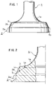
- Fig. 1 illustrates a valve head 1a of an exhaust poppet valve intermediate 1 before working.
- the valve intermediate 1 is made of austenitic heat-resistant steel, such as SUH 37 or Ni heat-resistant alloy such as NCF 80A and NCF 751, and solution treatment is thus made thereon.
- the external diameter of a marginal portion 1b of the valve head 1a of the poppet valve intermediate 1 is slightly smaller than the external diameter of a marginal portion 2a of a poppet valve 2 after working as shown by a dotted line.
- An isosceles-triangle-sectioned lobe 3 is formed on the valve head 1a at a position which is corresponding to a tapered valve face 2b of the worked poppet valve 2.
- the lobe 3 is plastically deformed into the tapered valve face 2b.
- a working rate is expressed by percentage and is difference in height between the lobe 3 and the valve face 2b divided by height of the lobe 3. As shown in Fig. 2, the difference is “L 1 " in the middle of the lobe, and “L 2 " near the inner circumferential end of the lobe 3.
- the working rate is the maximum in the middle and gradually decreases towards inner and outer circumferential ends of the lobe 3. There is no difference in height between the lobe 3 and valve face at the outer circumferential end "S" of the valve face 2b and its working rate becomes zero.
- the working rate is 30 to 60% in the middle of the lobe 3 and is 5 to 10% at the inner circumferential end of the lobe 3.
- valve head 1a of the intermediate 1 is heated at temperature between 530 and 620°C, preferably between 550 and 600°C, and forged by a forging device as shown in Fig. 3.
- Fig. 7 is a graph which illustrates relationship between forging temperature and deformation resistance.
- deformation resistance is high. So, to harden the lobe 3 by plastic deformation, it requires a high energy, and to work a big poppet valve, it requires a large-sized forging device which provides high compression force. If heating temperature exceeds 620°C, deformation resistance decreases, and sufficient hardness by hardening cannot be obtained, so that craking occurs. In view of safety, the upper limit is set to 620°C.
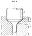
- the intermediate 1 heated to the above temperature is vertically inserted into a bore 4a of a die of the forging device, putting the valve head 1a as top.
- the bore of the die 4 is matched with the valve head 1 of the poppet valve 2 in figure.
- a punch 5 is moved up and down by a predetermined stroke with respect to the bore 4a.
- the intermediate 1 is put in the bore 4a of the die 4, and then, as shown in Fig. 4, the punch 5 is lowered to forge the intermediate 1, so that the final poppet valve 2 is obtained.
- the lobe 3 of the intermediate 1 is deformed in directions of inner and outer circumference as shown by arrows from the middle which has the maximum working rate and the marginal portion 1b of the valve head 1a is deformed in an outward radial direction.
- the whole valve face 2b of the worked poppet valve 2 is uniformly hardened at a fixed depth, thereby obtaining high wear-resistant poppet valve 2 which does not cause local wear.
- Heat resistant Ni alloy NCF80A is employed. Working rates in the middle, and at the outer and inner circumferential end of the lobe are set to about 45%, 0 and about 7% respectively at about 580°C and forged by the foregoing procedures. After working, Vickers hardness at the surface of the valve face 2b of an obtained product ranges 470 to 480Hv at any points without any significant variation. Cracking does not occur not only on the surface but also inside of the valve face 2b, and a high quality poppet valve 2 is thus obtained.
- Age treatment such as air cooling at 700°C for 10 hours may be further carried out to the forged poppet valve 2, thereby increasing hardness of the valve face 2b.
- the forging device to deform the lobe 3 of the intermediate plastically and harden it, the forging device is employed, but the lobe 3 is pressed from the inside to the outside and deformed plastically in a poppet valve which does not require so high pressing force.
- the lobe 3 may be compressed several times vertically by a hammer of a forging device while the intermediate is rotated around a vertical axis slowly, so that it is gradually deformed every circumferential section.
- a hammer of a forging device may be rotated around a vertical axis slowly, so that it is gradually deformed every circumferential section.
Landscapes
- Engineering & Computer Science (AREA)
- General Engineering & Computer Science (AREA)
- Mechanical Engineering (AREA)
- Physics & Mathematics (AREA)
- Geometry (AREA)
- Forging (AREA)
- Lift Valve (AREA)
Applications Claiming Priority (4)
| Application Number | Priority Date | Filing Date | Title |
|---|---|---|---|
| JP29804999 | 1999-10-20 | ||
| JP29804999A JP2001115808A (ja) | 1999-10-20 | 1999-10-20 | エンジンバルブにおける弁フェース部の硬化方法 |
| JP30228599 | 1999-10-25 | ||
| JP30228599A JP4361649B2 (ja) | 1999-10-25 | 1999-10-25 | エンジンバルブにおける弁フェース部の硬化方法 |
Publications (2)
| Publication Number | Publication Date |
|---|---|
| EP1094202A2 true EP1094202A2 (de) | 2001-04-25 |
| EP1094202A3 EP1094202A3 (de) | 2002-08-14 |
Family
ID=26561356
Family Applications (1)
| Application Number | Title | Priority Date | Filing Date |
|---|---|---|---|
| EP00101170A Withdrawn EP1094202A3 (de) | 1999-10-20 | 2000-01-21 | Verfahren zum Härten vom Hubventilkopf |
Country Status (4)
| Country | Link |
|---|---|
| US (1) | US6295731B1 (de) |
| EP (1) | EP1094202A3 (de) |
| KR (1) | KR20010039528A (de) |
| CN (1) | CN1305051A (de) |
Cited By (1)
| Publication number | Priority date | Publication date | Assignee | Title |
|---|---|---|---|---|
| EP3088776A4 (de) * | 2014-08-27 | 2017-04-05 | Nittan Valve Co., Ltd. | Kegelventil und verfahren zur herstellung davon |
Families Citing this family (6)
| Publication number | Priority date | Publication date | Assignee | Title |
|---|---|---|---|---|
| US6385847B1 (en) * | 2000-09-13 | 2002-05-14 | Eaton Corporation | Seat faced engine valves and method of making seat faced engine valves |
| US20090084155A1 (en) * | 2007-09-28 | 2009-04-02 | Ryan Chase | Method to Form Pin Having Void Reducing Pin Head and Flattening Head to Perform the Method |
| US8978248B2 (en) * | 2011-10-14 | 2015-03-17 | Nittan Valve Co., Ltd. | Method of manufacturing a valve for an internal combustion engine |
| IN2014CN03160A (de) | 2011-10-14 | 2015-07-03 | Nittan Valva | |
| KR101426786B1 (ko) * | 2012-06-14 | 2014-08-05 | 니탄 밸브 가부시키가이샤 | 포펫 밸브의 페이스부의 형성 방법 및 이 형성 방법에 의한 페이스부를 가지는 포펫 밸브 |
| DK177960B1 (en) * | 2014-04-08 | 2015-02-02 | Man Diesel & Turbo Deutschland | An exhaust valve for an internal combustion engine |
Family Cites Families (7)
| Publication number | Priority date | Publication date | Assignee | Title |
|---|---|---|---|---|
| US1984751A (en) * | 1932-11-28 | 1934-12-18 | Thompson Prod Inc | Method of making hollow valves |
| US3319321A (en) * | 1964-01-10 | 1967-05-16 | Eaton Mfg Co | Method of making engine valve |
| US3649380A (en) * | 1969-04-14 | 1972-03-14 | Trw Inc | Method of manufacturing hard faced exhaust valves |
| US4741080A (en) * | 1987-02-20 | 1988-05-03 | Eaton Corporation | Process for providing valve members having varied microstructure |
| JP2547429B2 (ja) * | 1987-12-04 | 1996-10-23 | 日本特殊陶業株式会社 | セラミック製バルブ |
| JPH03242408A (ja) * | 1990-02-16 | 1991-10-29 | Aisan Ind Co Ltd | 中空エンジンバルブの製造方法 |
| JP2925945B2 (ja) | 1994-08-24 | 1999-07-28 | 日鍛バルブ株式会社 | 内燃機関用バルブの製造方法 |
-
2000
- 2000-01-20 US US09/488,160 patent/US6295731B1/en not_active Expired - Fee Related
- 2000-01-21 EP EP00101170A patent/EP1094202A3/de not_active Withdrawn
- 2000-01-27 KR KR1020000003964A patent/KR20010039528A/ko not_active Withdrawn
- 2000-02-14 CN CN00100812A patent/CN1305051A/zh active Pending
Non-Patent Citations (1)
| Title |
|---|
| None |
Cited By (2)
| Publication number | Priority date | Publication date | Assignee | Title |
|---|---|---|---|---|
| EP3088776A4 (de) * | 2014-08-27 | 2017-04-05 | Nittan Valve Co., Ltd. | Kegelventil und verfahren zur herstellung davon |
| US10473002B2 (en) | 2014-08-27 | 2019-11-12 | Nittan Valve Co., Ltd. | Poppet valve and method for manufacturing same |
Also Published As
| Publication number | Publication date |
|---|---|
| US6295731B1 (en) | 2001-10-02 |
| CN1305051A (zh) | 2001-07-25 |
| EP1094202A3 (de) | 2002-08-14 |
| KR20010039528A (ko) | 2001-05-15 |
Similar Documents
| Publication | Publication Date | Title |
|---|---|---|
| GB2051634A (en) | Forging of a camshaft | |
| EP2517806B1 (de) | Verfahren zur herstellung eines ventilschirmteils eines motorhohlventils, pressvorrichtung eines ventilschirmteils eines motorhohlventils und motorhohlventil | |
| KR20140022827A (ko) | 포펫 밸브의 페이스부의 형성 방법 및 이 형성 방법에 의한 페이스부를 가지는 포펫 밸브 | |
| US6354001B1 (en) | Method of manufacturing a Ti alloy poppet value | |
| US6295731B1 (en) | Method of hardening a valve face of a poppet valve | |
| US4399681A (en) | Forging of an article having a plurality of longitudinally arranged protuberances | |
| EP1950384B1 (de) | Kühlmittel enthaltendes hohles tellerventil und herstellungsverfahren dafür | |
| WO2010016227A1 (ja) | スプリング・リテーナ及びスプリング・システム | |
| JP2000505148A (ja) | 内燃機関用の排気弁 | |
| US6938816B2 (en) | Methods of manufacturing diffusion bonded products and products manufactured by such methods | |
| JP4361649B2 (ja) | エンジンバルブにおける弁フェース部の硬化方法 | |
| JP2001115808A (ja) | エンジンバルブにおける弁フェース部の硬化方法 | |
| US9015940B2 (en) | Method of manufacturing a valve for an internal combustion engine | |
| WO2021199190A1 (ja) | エンジンのポペットバルブの製造方法 | |
| JPH11270320A (ja) | 内燃機関用バルブの製法及びその製法により成形されたバルブ | |
| JP3862790B2 (ja) | 高圧燃料噴射管材およびその製造方法 | |
| JPH09329008A (ja) | 内燃機関用バルブスプリングリテーナ及びその加工方法 | |
| JP2000145416A (ja) | 内燃機関用バルブスプリングリテ―ナ及びその加工方法 | |
| JPH09170490A (ja) | 内燃機関用鋳鉄ピストン | |
| US20250205772A1 (en) | Method and unit for manufacturing an elongate intermediate part by hot forging | |
| US20050188738A1 (en) | Forged flange cylinder liner and method of manufacture | |
| JP2817029B2 (ja) | 内燃機関用給−排気弁の硬化方法 | |
| JPH1181932A (ja) | エンジン用吸気弁の成形方法 | |
| CN110977625B (zh) | 一种提高气门盘锥面的耐磨性且减小表面粗糙度的方法 | |
| JP2001121239A (ja) | エンジンバルブにおける傘部の鍛造方法 |
Legal Events
| Date | Code | Title | Description |
|---|---|---|---|
| PUAI | Public reference made under article 153(3) epc to a published international application that has entered the european phase |
Free format text: ORIGINAL CODE: 0009012 |
|
| AK | Designated contracting states |
Kind code of ref document: A2 Designated state(s): AT BE CH CY DE DK ES FI FR GB GR IE IT LI LU MC NL PT SE |
|
| AX | Request for extension of the european patent |
Free format text: AL;LT;LV;MK;RO;SI |
|
| PUAL | Search report despatched |
Free format text: ORIGINAL CODE: 0009013 |
|
| 17P | Request for examination filed |
Effective date: 20020610 |
|
| AK | Designated contracting states |
Kind code of ref document: A3 Designated state(s): AT BE CH CY DE DK ES FI FR GB GR IE IT LI LU MC NL PT SE |
|
| AX | Request for extension of the european patent |
Free format text: AL;LT;LV;MK;RO;SI |
|
| RIC1 | Information provided on ipc code assigned before grant |
Free format text: 7F 01L 3/02 A, 7F 01L 3/20 B, 7B 21K 1/22 B |
|
| AKX | Designation fees paid |
Designated state(s): DE GB |
|
| STAA | Information on the status of an ep patent application or granted ep patent |
Free format text: STATUS: THE APPLICATION IS DEEMED TO BE WITHDRAWN |
|
| 18D | Application deemed to be withdrawn |
Effective date: 20050801 |