EP1096148A2 - Dispositif pour variation de débit d'une pompe - Google Patents
Dispositif pour variation de débit d'une pompe Download PDFInfo
- Publication number
- EP1096148A2 EP1096148A2 EP00123142A EP00123142A EP1096148A2 EP 1096148 A2 EP1096148 A2 EP 1096148A2 EP 00123142 A EP00123142 A EP 00123142A EP 00123142 A EP00123142 A EP 00123142A EP 1096148 A2 EP1096148 A2 EP 1096148A2
- Authority
- EP
- European Patent Office
- Prior art keywords
- shaft
- groove
- pump
- sleeve
- openings
- Prior art date
- Legal status (The legal status is an assumption and is not a legal conclusion. Google has not performed a legal analysis and makes no representation as to the accuracy of the status listed.)
- Granted
Links
Images


Classifications
-
- F—MECHANICAL ENGINEERING; LIGHTING; HEATING; WEAPONS; BLASTING
- F02—COMBUSTION ENGINES; HOT-GAS OR COMBUSTION-PRODUCT ENGINE PLANTS
- F02M—SUPPLYING COMBUSTION ENGINES IN GENERAL WITH COMBUSTIBLE MIXTURES OR CONSTITUENTS THEREOF
- F02M63/00—Other fuel-injection apparatus having pertinent characteristics not provided for in groups F02M39/00 - F02M57/00 or F02M67/00; Details, component parts, or accessories of fuel-injection apparatus, not provided for in, or of interest apart from, the apparatus of groups F02M39/00 - F02M61/00 or F02M67/00; Combination of fuel pump with other devices, e.g. lubricating oil pump
- F02M63/02—Fuel-injection apparatus having several injectors fed by a common pumping element, or having several pumping elements feeding a common injector; Fuel-injection apparatus having provisions for cutting-out pumps, pumping elements, or injectors; Fuel-injection apparatus having provisions for variably interconnecting pumping elements and injectors alternatively
- F02M63/0225—Fuel-injection apparatus having a common rail feeding several injectors ; Means for varying pressure in common rails; Pumps feeding common rails
-
- F—MECHANICAL ENGINEERING; LIGHTING; HEATING; WEAPONS; BLASTING
- F02—COMBUSTION ENGINES; HOT-GAS OR COMBUSTION-PRODUCT ENGINE PLANTS
- F02M—SUPPLYING COMBUSTION ENGINES IN GENERAL WITH COMBUSTIBLE MIXTURES OR CONSTITUENTS THEREOF
- F02M59/00—Pumps specially adapted for fuel-injection and not provided for in groups F02M39/00 -F02M57/00, e.g. rotary cylinder-block type of pumps
- F02M59/20—Varying fuel delivery in quantity or timing
- F02M59/36—Varying fuel delivery in quantity or timing by variably-timed valves controlling fuel passages to pumping elements or overflow passages
-
- F—MECHANICAL ENGINEERING; LIGHTING; HEATING; WEAPONS; BLASTING
- F04—POSITIVE - DISPLACEMENT MACHINES FOR LIQUIDS; PUMPS FOR LIQUIDS OR ELASTIC FLUIDS
- F04B—POSITIVE-DISPLACEMENT MACHINES FOR LIQUIDS; PUMPS
- F04B49/00—Control, e.g. of pump delivery, or pump pressure of, or safety measures for, machines, pumps, or pumping installations, not otherwise provided for, or of interest apart from, groups F04B1/00 - F04B47/00
- F04B49/002—Hydraulic systems to change the pump delivery
-
- F—MECHANICAL ENGINEERING; LIGHTING; HEATING; WEAPONS; BLASTING
- F04—POSITIVE - DISPLACEMENT MACHINES FOR LIQUIDS; PUMPS FOR LIQUIDS OR ELASTIC FLUIDS
- F04B—POSITIVE-DISPLACEMENT MACHINES FOR LIQUIDS; PUMPS
- F04B49/00—Control, e.g. of pump delivery, or pump pressure of, or safety measures for, machines, pumps, or pumping installations, not otherwise provided for, or of interest apart from, groups F04B1/00 - F04B47/00
- F04B49/22—Control, e.g. of pump delivery, or pump pressure of, or safety measures for, machines, pumps, or pumping installations, not otherwise provided for, or of interest apart from, groups F04B1/00 - F04B47/00 by means of valves
- F04B49/225—Control, e.g. of pump delivery, or pump pressure of, or safety measures for, machines, pumps, or pumping installations, not otherwise provided for, or of interest apart from, groups F04B1/00 - F04B47/00 by means of valves with throttling valves or valves varying the pump inlet opening or the outlet opening
Definitions
- the invention relates to a device for generating a variable volume flow for a pump, in particular for Use in a high pressure injection system is suitable.
- Adjustable throttle valves are used which is proportional due to a change in the throttle cross section Allow changing the volume flow to the pump with the maximum cross sections of the throttle valves on a maximum delivery volume of the pump at full load of the internal combustion engine are designed. This results in one of the Speed of the pump dependent adjustment range of the throttle valves, where at a low pump speed and thus a low maximum conveyable volume flow the usable adjustment range of the Throttle valves are severely restricted. Only at maximum pump speed and thus maximum volume flow can be the full Adjustment range of the throttle valves can be used. Farther can with a central throttling of the inlet at a Pump with several displacement elements Flow rate fluctuations occur to the individual displacement elements.
- the object of the present invention is a device to provide a variable volume flow, with which an optimal delivery rate setting can be achieved in terms of energy efficiency the pump for all speeds and load ranges and which can be done by a simple structure and distinguishes small installation space.
- the device for generating a variable volume flow for a pump includes and in Also referred to as an adjusting device first component with an inlet breakthrough that with a Fuel inlet is connected, and a second component with at least two outlet openings lying in one plane and each with an inlet assigned to the pump are connected to, wherein the first and the second component arranged inside each other and axially displaceable are to cover the inlet opening with the Adjust outlet openings and being one of the components rotates in angular synchronism with the drive shaft of the pump and the other component is designed to be non-rotatable.
- the invention ensures that with each drive shaft rotation the displacement elements an available, pre-measured volume flow is supplied, whereby for all pump speeds have a consistently large setting range to influence the volume flow is guaranteed.
- the Setting the degree of filling of the displacement spaces is thus of the speed of the pump independently. It also becomes even Distribution of the volume flow to the individual Displacement elements of the pump achieved.
- the arrangement of the outlet openings in one Level ensures a compact design of the adjustment device, which is therefore also easy to adapt to the space available can be adapted to an internal combustion engine.
- One level means that all outlet openings are at the same level in relation to the Start the longitudinal axis of the component with the outlet openings and end.
- the displacement elements the pump from a rotating shaft for example one Cam or eccentric shaft driven with the rotary movement of the rotatable component of the adjusting device is angularly synchronized.
- the shaft can be made in one piece with the rotatable component be designed so that a particularly compact design can be achieved.
- the rotatably designed component then preferably has one formed as an axial channel inlet, which via a Prefeed pump connected to a fuel tank is, the inlet opening radial the axial channel leads to the outside through the outer surface of the component.
- the second component is then designed as a hollow cylinder, wherein the preferably identical outlet openings are distributed parallel to one another and radially around the component. This configuration enables particularly simple production, because the number of breakthroughs and holes in the components the adjustment device is kept to a minimum.
- the non-rotatable component that the outlet openings has to design in two parts, with a axially displaceable sleeve in which the openings are arranged are, and a housing.
- the shape of the inlet opening or the outlet openings is chosen so that depending on the axial position of these components different phase lengths, d.
- a defined displacement element of the pump Volume can be supplied.
- the rotary movements are preferred the component of the adjusting device and the pump synchronized that the coverage of the inlet breakthrough with the respective outlet opening in or before the upper one Dead center of the associated displacement element of the pump begins and at maximum funding in or after bottom dead center ends.
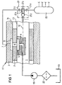
- a fuel injection system shown schematically in FIG. 1 has a high pressure pump 21.
- the high pressure pump 21 is a three-cylinder pump (radial piston pump) with three um Pistons offset from each other by 120 °.
- Figure 1 is schematically one of these pistons 21a shown by a Shaft 1 is driven with an eccentric 21d. Instead of However, an eccentric shaft can also use a camshaft become.
- the piston 21a of the high pressure pump 21 is in one Cylinder 21b arranged to which an intake valve 21c and an Exhaust valve 21e is connected. Wave 1 is pending the high pressure pump 21 and is part of an adjustment device here 11 for metering the fuel feed to the high pressure pump 21.
- an inlet channel 4 is provided, which extends from an end face the shaft 1 along the shaft axis 12 into the shaft extends into it.
- the inlet channel 4 is with an outlet a pre-feed pump 18 connected, the inflow via a Filter 20 connected to a fuel tank 19 is.
- the inlet channel 4 is in the area of the shaft 1 the adjusting device 11 at right angles to the shaft axis 12 bent and is connected to a groove 5 which the axially extending circumferential surface 13 of the shaft 1 breaks through.
- the shaft 1 is still in the region of the adjusting device 11 arranged in a housing 3, which as a cylindrical Hollow body is formed and a continuous inner bore 31 for receiving the shaft 1.
- a cylindrical housing 3 are preferably perpendicular to the axis through the housing, which corresponds to the shaft axis 12, outlet channels 7 are provided, which extend from the outside into the housing 3 and each communicate with a groove 8.
- the groove 8 breaks through the inner wall of the housing 3 to the inner bore 31 out.
- the number of outlet channels provided on the housing 3 7 with grooves 8 corresponds to the number of cylinders in the high-pressure pump 21. Since it is in the embodiment shown in Figure 1 is a three-cylinder high-pressure pump, three outlet channels 7 are provided, of which in FIG. 1 only one is shown.
- Each outlet channel 7 is then one Inlet to an inlet valve 21c of a cylinder 21b High pressure pump 21 connected.
- the grooves 8 in the housing 3 are in a plane perpendicular to the housing and therefore perpendicular to the shaft axis 12 equally spaced from each other on the inner wall of the housing 3 arranged.
- three-cylinder pump means this means that the grooves 8 are offset from one another by 120 ° are formed on the inner wall of the housing 3.
- the most Housing 3 formed grooves 8 and attached to the shaft 1 Groove 5 are further arranged such that their Cross-sectional areas are at least partially opposite. An embodiment is therefore preferred in which, as in FIG 1, the groove 5 on the shaft 1 and the grooves 8 lie on the housing 3 in one plane.
- the shaft 1 is further provided with a cylindrical sleeve 2.
- the sleeve 2 is non-rotatable relative to the shaft 1, however axially displaceable.
- the sleeve 2 still has Breakthroughs 6, the number of breakthroughs 6 being the number corresponds to the grooves 8 in the housing 3. Breakthroughs 6 are distributed around the sleeve 2 that they with the grooves 8 in Connect housing 3.
- Figure 2 is a settlement the outer surfaces of the shaft 1 and the sleeve 2 shown, from which the shape and arrangement of the groove 5 on the shaft 1 or the openings 6 in the sleeve 2 results.
- the openings 6a, 6b, 6c are elongated Slits with rounded edges executed, their contours are essentially identical.
- the openings 6a, 6b, 6c are parallel to the sleeve axis corresponds to the shaft axis 13, oriented and even spaced apart over the sleeve 2, with all openings lie in a plane perpendicular to the sleeve axis.
- the groove 5 is designed as a slot similar to the openings 6a, 6b, 6c, however at an angle to the circumferential direction and Axis of the shaft 1 oriented, the groove 5 over a Angular range of 180 ° extends over the outer surface of the shaft 1.
- Deviating 2 is in the representation in Figure 3 and 4 on a rounding of the edges of the openings 6a, 6b, 6c and the groove 5 waived.
- FIG the groove 5 on the shaft 1 with respect to the circumferential direction and oriented the axial direction of the shaft so that at a Rotation of the shaft by 180 ° the cross-sectional area of the groove 5 with the cross-sectional areas of the openings 6a, 6b, 6c overlaid.
- the adjusting device 11 shown in the figures works as follows: The adjusting device 11 is operated by the prefeed pump 18 a fuel flow is continuously supplied, the filter 20 from the fuel tank 19 is sucked in. The fuel is above that on the Shaft axis 13 arranged on the shaft 1 inlet channel 4 in the adjustment device fed. From inlet duct 4 the fuel then continues to the groove 5 on the lateral surface 13 the shaft 1 out. The fuel from the groove 5 corresponding axial position of the shaft 1 via one of the Breakthroughs 6a, 6b, 6c of the rotatable sleeve 2 to the with the corresponding breakthrough related groove 8 delivered and from there via the associated outlet channel 7 to the corresponding cylinder 21b of the high pressure pump 21 forwarded. The high pressure pump 21 then sucks the fuel the inlet valve 21c and feeds it through the outlet valve 21e compresses into the rail 22.
- the fuel flow from the groove 5 of the shaft 1 into the openings 6a, 6b, 6c of the sleeve 2 depends on the axial position the sleeve 2 of the shaft 1.
- the fuel flow then begins if due to the rotation of the shaft 1, the cross-sectional area the groove 5 covered with an opening 6.
- the interruption of the fuel flow occurs when the groove 5 is due the further rotation of shaft 1 under the corresponding Breakthrough 6 of the sleeve 2 has run out and thus the cross-sectional areas are no longer covered.
- the high pressure pump 21 from one with an eccentric provided shaft 1 is driven, it means that a Connection between an opening 6, one of the cylinders is assigned and the groove 5 of the shaft 1 over an angle of rotation of at least 180 °.
- Figures 2 and 4 show an orientation of the sleeve 2 to the rotating Wave 1 at which a maximum volume flow from the groove 5 of the shaft 1 into the openings 6 of the sleeve 2.
- the Breakthroughs 6 are oriented to the groove 5 that the Groove 5 when the shaft 1 rotates essentially Breakthroughs 6 swept over their entire length.
- a connection between the groove 5 and the openings 6 is then per opening for a rotation angle of 180 °, so that the cylinder 21b associated with the corresponding opening the pump 21 can be filled to the maximum.
- the inflow to the cylinder 21b is preferably so matched that always in the top dead center of the associated Piston 21a the inlet by beginning the overlap of the groove 5 is opened with the corresponding opening 6.
- the closing time is variable and is determined by the axial Position of the sleeve 2 set, one position between zero funding, d. H. no overlap of the groove 5 with the breakthroughs 6 during a complete revolution of the Wave, and full funding, d. H. Coverage between the groove 5 and the breakthroughs 6 each work over 180 ° can.
- the adjustment device makes it possible to with each rotation of the high pressure pump 21, a meterable, pre-measured volume of the cylinders of the high pressure pump 21 feed. With the resulting variable The degree of filling of the cylinders of the high pressure pump 21 thus results a variable fuel volume flow between zero and full load. The setting of the filling level of the cylinders is still decoupled from the speed of the high pressure pump, so the possible adjustment range for all speeds the high pressure pump 21 is the same size.
- the dosage is done by changing the axial position of the sleeve 2 to the shaft 1, which means the angle of rotation between the beginning and end of the overlap changed between the groove 5 and the openings 6 becomes.
- the rotational movement of shaft 1 is carried out at an angle-synchronous manner the position of the pistons of the high pressure pump 21, preferably always open in the area of the top dead center of the piston and at every piston position down to the range of bottom dead center is closed.
- the Breakthroughs 6 on the sleeve 2 parallel to each other, in one A plane perpendicular to the axis of the sleeve can be compact Achieve the design of the sleeve 2 and thus the adjusting device.
- only the one groove 5 in the shaft 1 is required, with all the openings 6 on the sleeve 2nd Fuel can be supplied. This makes it easy to manufacture especially shaft 1 reached.
- the groove 5 is in the shaft 1 and the openings 6 in the sleeve 2 formed as slots.
- the groove 5 and the openings 6 can also be designed with any shape. So is it z. B. possible to form the groove 5 serpentine. This can be used, for example, to create a linear relationship between the displacement of the sleeve 2 and the degree of filling to reach the cylinder of the high pressure pump 21.
- the sleeve instead of using a sleeve 2 between the housing 3 and the shaft 1 in the adjusting device 11 can also the sleeve be integrated directly into the housing, the housing then is slidably disposed to the shaft. Alternatively there is also the possibilities instead of the housing or the sleeve To design the shaft to be slidable.
Landscapes
- Engineering & Computer Science (AREA)
- Mechanical Engineering (AREA)
- General Engineering & Computer Science (AREA)
- Chemical & Material Sciences (AREA)
- Combustion & Propulsion (AREA)
- Fuel-Injection Apparatus (AREA)
- Details Of Reciprocating Pumps (AREA)
- Structures Of Non-Positive Displacement Pumps (AREA)
Applications Claiming Priority (2)
| Application Number | Priority Date | Filing Date | Title |
|---|---|---|---|
| DE19952000 | 1999-10-28 | ||
| DE1999152000 DE19952000C2 (de) | 1999-10-28 | 1999-10-28 | Vorrichtung zum Erzeugen eines variablen Volumenstroms für eine Pumpe |
Publications (4)
| Publication Number | Publication Date |
|---|---|
| EP1096148A2 true EP1096148A2 (fr) | 2001-05-02 |
| EP1096148A3 EP1096148A3 (fr) | 2006-07-19 |
| EP1096148B1 EP1096148B1 (fr) | 2008-01-02 |
| EP1096148B8 EP1096148B8 (fr) | 2008-05-07 |
Family
ID=7927206
Family Applications (1)
| Application Number | Title | Priority Date | Filing Date |
|---|---|---|---|
| EP20000123142 Expired - Lifetime EP1096148B8 (fr) | 1999-10-28 | 2000-10-25 | Dispositif pour variation de débit d'une pompe |
Country Status (2)
| Country | Link |
|---|---|
| EP (1) | EP1096148B8 (fr) |
| DE (2) | DE19952000C2 (fr) |
Families Citing this family (1)
| Publication number | Priority date | Publication date | Assignee | Title |
|---|---|---|---|---|
| GB0917936D0 (en) | 2009-10-13 | 2009-11-25 | 3D Printer Aps | Three-dimensional printer |
Family Cites Families (6)
| Publication number | Priority date | Publication date | Assignee | Title |
|---|---|---|---|---|
| DE594336C (de) * | 1930-12-22 | 1934-03-15 | Magneti Marelli Spa | Brennstoffeinspritzpumpe |
| GB459578A (en) * | 1935-09-13 | 1937-01-11 | Bosch Robert | Improvements in fuel injection pumps for internal combustion engines |
| DE724841C (de) * | 1938-07-19 | 1942-09-07 | Hans Polland | Verteiler fuer Brennstoff-Einspritzanlagen |
| DE2044015A1 (de) * | 1970-09-04 | 1971-06-16 | Kugelfischer Georg Schafer & Co, 8720 Schweinfurt | Stromungsmittel Rotationsverteiler |
| ES2115883T3 (es) * | 1993-09-14 | 1998-07-01 | Lucas Ind Plc | Dispositivo de alimentacion de carburante. |
| DE19854509C2 (de) * | 1998-11-25 | 2000-11-23 | Siemens Ag | Vorrichtung zum Erzeugen eines variablen Volumenstromes bei einer Kraftstoffzuführung |
-
1999
- 1999-10-28 DE DE1999152000 patent/DE19952000C2/de not_active Expired - Fee Related
-
2000
- 2000-10-25 EP EP20000123142 patent/EP1096148B8/fr not_active Expired - Lifetime
- 2000-10-25 DE DE50014889T patent/DE50014889D1/de not_active Expired - Lifetime
Also Published As
| Publication number | Publication date |
|---|---|
| DE50014889D1 (de) | 2008-02-14 |
| EP1096148B1 (fr) | 2008-01-02 |
| DE19952000C2 (de) | 2001-08-16 |
| EP1096148A3 (fr) | 2006-07-19 |
| EP1096148B8 (fr) | 2008-05-07 |
| DE19952000A1 (de) | 2001-05-10 |
Similar Documents
| Publication | Publication Date | Title |
|---|---|---|
| EP1283366B1 (fr) | Pompe à pistons radiaux et méthode de contròle | |
| DE69424448T2 (de) | Kraftstoffzufuhreinrichtung | |
| EP0150471B1 (fr) | Pompe d'injection de combustible | |
| DE4308506A1 (de) | Ölpumpensystem | |
| EP0273225B1 (fr) | Pompe d'injection de combustible pour moteurs à combustion interne | |
| DE3346799A1 (de) | Verteiler-brennstoffeinspritzpumpe | |
| DE4441506A1 (de) | Kraftstoffeinspritzpumpe | |
| EP0166995A2 (fr) | Pompe d'injection de carburant pour moteurs à combustion interne | |
| DE69505456T2 (de) | Verteiler-Kraftstoffeinspritzpumpe | |
| DE19952000C2 (de) | Vorrichtung zum Erzeugen eines variablen Volumenstroms für eine Pumpe | |
| DE4135904A1 (de) | Kolbenpumpe, insbesondere radialkolbenpumpe | |
| DE3718499A1 (de) | Rotationsverteiler-kraftstoffeinspritzpumpe | |
| EP1049869B1 (fr) | Dispositif pour produire un debit variable dans une alimentation en carburant | |
| DE3545050A1 (de) | Brennstoff-einspritzpumpe fuer eine wenigstens vierzyindrige brennkraftmaschine | |
| DE69604443T2 (de) | Kraftstoffzufuhreinrichtung | |
| DE69101608T2 (de) | Kraftstoffpumpenvorrichtung. | |
| EP0863308A1 (fr) | Pompe à piston pour refoulement des liquides | |
| WO1988005128A1 (fr) | Pompe d'injection de carburant pour moteurs a combustion interne | |
| DE60306319T2 (de) | Hydraulische Pumpe | |
| DE3545145A1 (de) | Brennstoff-einspritzpumpe fuer eine wenigstens vierzylindrige brennkraftmaschine | |
| WO2001036820A9 (fr) | Pompe hydraulique a pistons | |
| DE10216205B4 (de) | Kraftstoffhochdruckpumpe mit Fördermengenregelung | |
| DE3215046A1 (de) | Einspritzsystem an einer brennkraftmaschine | |
| EP1096135B1 (fr) | Dispositif d'injection pour un moteur à combustion interne | |
| CH644681A5 (en) | Lubricant piston feed pump for the load-dependent lubrication of engines, especially of piston engines |
Legal Events
| Date | Code | Title | Description |
|---|---|---|---|
| PUAI | Public reference made under article 153(3) epc to a published international application that has entered the european phase |
Free format text: ORIGINAL CODE: 0009012 |
|
| AK | Designated contracting states |
Kind code of ref document: A2 Designated state(s): AT BE CH CY DE DK ES FI FR GB GR IE IT LI LU MC NL PT SE |
|
| AX | Request for extension of the european patent |
Free format text: AL;LT;LV;MK;RO;SI |
|
| PUAL | Search report despatched |
Free format text: ORIGINAL CODE: 0009013 |
|
| AK | Designated contracting states |
Kind code of ref document: A3 Designated state(s): AT BE CH CY DE DK ES FI FR GB GR IE IT LI LU MC NL PT SE |
|
| AX | Request for extension of the european patent |
Extension state: AL LT LV MK RO SI |
|
| 17P | Request for examination filed |
Effective date: 20060821 |
|
| 17Q | First examination report despatched |
Effective date: 20060928 |
|
| AKX | Designation fees paid |
Designated state(s): DE FR GB IT |
|
| GRAP | Despatch of communication of intention to grant a patent |
Free format text: ORIGINAL CODE: EPIDOSNIGR1 |
|
| GRAS | Grant fee paid |
Free format text: ORIGINAL CODE: EPIDOSNIGR3 |
|
| GRAA | (expected) grant |
Free format text: ORIGINAL CODE: 0009210 |
|
| RAP1 | Party data changed (applicant data changed or rights of an application transferred) |
Owner name: SIEMENS VDO AUTOMOTIVE AG |
|
| AK | Designated contracting states |
Kind code of ref document: B1 Designated state(s): DE FR GB IT |
|
| REG | Reference to a national code |
Ref country code: GB Ref legal event code: FG4D Free format text: NOT ENGLISH |
|
| REF | Corresponds to: |
Ref document number: 50014889 Country of ref document: DE Date of ref document: 20080214 Kind code of ref document: P |
|
| RAP2 | Party data changed (patent owner data changed or rights of a patent transferred) |
Owner name: VDO AUTOMOTIVE AG |
|
| RAP2 | Party data changed (patent owner data changed or rights of a patent transferred) |
Owner name: CONTINENTAL AUTOMOTIVE GMBH |
|
| GBV | Gb: ep patent (uk) treated as always having been void in accordance with gb section 77(7)/1977 [no translation filed] | ||
| ET | Fr: translation filed | ||
| PLBE | No opposition filed within time limit |
Free format text: ORIGINAL CODE: 0009261 |
|
| STAA | Information on the status of an ep patent application or granted ep patent |
Free format text: STATUS: NO OPPOSITION FILED WITHIN TIME LIMIT |
|
| 26N | No opposition filed |
Effective date: 20081003 |
|
| PG25 | Lapsed in a contracting state [announced via postgrant information from national office to epo] |
Ref country code: GB Free format text: LAPSE BECAUSE OF FAILURE TO SUBMIT A TRANSLATION OF THE DESCRIPTION OR TO PAY THE FEE WITHIN THE PRESCRIBED TIME-LIMIT Effective date: 20080102 |
|
| PG25 | Lapsed in a contracting state [announced via postgrant information from national office to epo] |
Ref country code: IT Free format text: LAPSE BECAUSE OF FAILURE TO SUBMIT A TRANSLATION OF THE DESCRIPTION OR TO PAY THE FEE WITHIN THE PRESCRIBED TIME-LIMIT Effective date: 20080102 |
|
| REG | Reference to a national code |
Ref country code: FR Ref legal event code: TP Owner name: CONTINENTAL AUTOMOTIVE GMBH, DE Effective date: 20111104 Ref country code: FR Ref legal event code: CD Owner name: CONTINENTAL AUTOMOTIVE GMBH, DE Effective date: 20111104 |
|
| PGFP | Annual fee paid to national office [announced via postgrant information from national office to epo] |
Ref country code: DE Payment date: 20141031 Year of fee payment: 15 |
|
| REG | Reference to a national code |
Ref country code: FR Ref legal event code: PLFP Year of fee payment: 16 |
|
| PGFP | Annual fee paid to national office [announced via postgrant information from national office to epo] |
Ref country code: FR Payment date: 20151023 Year of fee payment: 16 |
|
| REG | Reference to a national code |
Ref country code: DE Ref legal event code: R119 Ref document number: 50014889 Country of ref document: DE |
|
| PG25 | Lapsed in a contracting state [announced via postgrant information from national office to epo] |
Ref country code: DE Free format text: LAPSE BECAUSE OF NON-PAYMENT OF DUE FEES Effective date: 20160503 |
|
| REG | Reference to a national code |
Ref country code: FR Ref legal event code: ST Effective date: 20170630 |
|
| PG25 | Lapsed in a contracting state [announced via postgrant information from national office to epo] |
Ref country code: FR Free format text: LAPSE BECAUSE OF NON-PAYMENT OF DUE FEES Effective date: 20161102 |