EP1096148B1 - Dispositif pour variation de débit d'une pompe - Google Patents
Dispositif pour variation de débit d'une pompe Download PDFInfo
- Publication number
- EP1096148B1 EP1096148B1 EP20000123142 EP00123142A EP1096148B1 EP 1096148 B1 EP1096148 B1 EP 1096148B1 EP 20000123142 EP20000123142 EP 20000123142 EP 00123142 A EP00123142 A EP 00123142A EP 1096148 B1 EP1096148 B1 EP 1096148B1
- Authority
- EP
- European Patent Office
- Prior art keywords
- shaft
- groove
- pump
- bushing
- apertures
- Prior art date
- Legal status (The legal status is an assumption and is not a legal conclusion. Google has not performed a legal analysis and makes no representation as to the accuracy of the status listed.)
- Expired - Lifetime
Links
Images

Classifications
-
- F—MECHANICAL ENGINEERING; LIGHTING; HEATING; WEAPONS; BLASTING
- F02—COMBUSTION ENGINES; HOT-GAS OR COMBUSTION-PRODUCT ENGINE PLANTS
- F02M—SUPPLYING COMBUSTION ENGINES IN GENERAL WITH COMBUSTIBLE MIXTURES OR CONSTITUENTS THEREOF
- F02M63/00—Other fuel-injection apparatus having pertinent characteristics not provided for in groups F02M39/00 - F02M57/00 or F02M67/00; Details, component parts, or accessories of fuel-injection apparatus, not provided for in, or of interest apart from, the apparatus of groups F02M39/00 - F02M61/00 or F02M67/00; Combination of fuel pump with other devices, e.g. lubricating oil pump
- F02M63/02—Fuel-injection apparatus having several injectors fed by a common pumping element, or having several pumping elements feeding a common injector; Fuel-injection apparatus having provisions for cutting-out pumps, pumping elements, or injectors; Fuel-injection apparatus having provisions for variably interconnecting pumping elements and injectors alternatively
- F02M63/0225—Fuel-injection apparatus having a common rail feeding several injectors ; Means for varying pressure in common rails; Pumps feeding common rails
-
- F—MECHANICAL ENGINEERING; LIGHTING; HEATING; WEAPONS; BLASTING
- F02—COMBUSTION ENGINES; HOT-GAS OR COMBUSTION-PRODUCT ENGINE PLANTS
- F02M—SUPPLYING COMBUSTION ENGINES IN GENERAL WITH COMBUSTIBLE MIXTURES OR CONSTITUENTS THEREOF
- F02M59/00—Pumps specially adapted for fuel-injection and not provided for in groups F02M39/00 -F02M57/00, e.g. rotary cylinder-block type of pumps
- F02M59/20—Varying fuel delivery in quantity or timing
- F02M59/36—Varying fuel delivery in quantity or timing by variably-timed valves controlling fuel passages to pumping elements or overflow passages
-
- F—MECHANICAL ENGINEERING; LIGHTING; HEATING; WEAPONS; BLASTING
- F04—POSITIVE - DISPLACEMENT MACHINES FOR LIQUIDS; PUMPS FOR LIQUIDS OR ELASTIC FLUIDS
- F04B—POSITIVE-DISPLACEMENT MACHINES FOR LIQUIDS; PUMPS
- F04B49/00—Control, e.g. of pump delivery, or pump pressure of, or safety measures for, machines, pumps, or pumping installations, not otherwise provided for, or of interest apart from, groups F04B1/00 - F04B47/00
- F04B49/002—Hydraulic systems to change the pump delivery
-
- F—MECHANICAL ENGINEERING; LIGHTING; HEATING; WEAPONS; BLASTING
- F04—POSITIVE - DISPLACEMENT MACHINES FOR LIQUIDS; PUMPS FOR LIQUIDS OR ELASTIC FLUIDS
- F04B—POSITIVE-DISPLACEMENT MACHINES FOR LIQUIDS; PUMPS
- F04B49/00—Control, e.g. of pump delivery, or pump pressure of, or safety measures for, machines, pumps, or pumping installations, not otherwise provided for, or of interest apart from, groups F04B1/00 - F04B47/00
- F04B49/22—Control, e.g. of pump delivery, or pump pressure of, or safety measures for, machines, pumps, or pumping installations, not otherwise provided for, or of interest apart from, groups F04B1/00 - F04B47/00 by means of valves
- F04B49/225—Control, e.g. of pump delivery, or pump pressure of, or safety measures for, machines, pumps, or pumping installations, not otherwise provided for, or of interest apart from, groups F04B1/00 - F04B47/00 by means of valves with throttling valves or valves varying the pump inlet opening or the outlet opening
Definitions
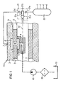
- the adjusting device 11 shown in the figures operates as follows: The adjusting device 11 is continuously supplied by the prefeed pump 18, a fuel flow, which is sucked through the filter 20 from the fuel tanks 19. The fuel is thereby fed via the arranged on the shaft axis 12 on the shaft 1 inlet channel 4 in the adjustment. From the inlet channel 4, the fuel is then passed on to the groove 5 on the lateral surface 13 of the shaft 1. From the groove 5, the fuel is discharged at a corresponding axial position of the shaft 1 via one of the openings 6a, 6b, 6c of the rotatable sleeve 2 to the standing with the corresponding breakthrough in connection groove 8 and from there via the associated outlet channel 7 to the corresponding Cylinder 21b of the high-pressure pump 21 forwarded. The high-pressure pump 21 then sucks the fuel via the inlet valve 21c and feeds it into the rail 22 in a compressed manner via the outlet valve 21e.
Landscapes
- Engineering & Computer Science (AREA)
- Mechanical Engineering (AREA)
- General Engineering & Computer Science (AREA)
- Chemical & Material Sciences (AREA)
- Combustion & Propulsion (AREA)
- Fuel-Injection Apparatus (AREA)
- Structures Of Non-Positive Displacement Pumps (AREA)
- Details Of Reciprocating Pumps (AREA)
Claims (8)
- Dispositif pour générer un débit volumétrique variable en liaison avec une pompe (21) d'un système d'injection à haute pression avec des injecteurs, le dispositif comportant au moins deux éléments de déplacement (1 ; 2, 3) comportant chacun un orifice d'arrivée, avec
un premier composant (1) qui comporte un passage d'admission (5) qui est relié à une admission (4), et avec
un deuxième composant (2, 3) qui comporte au moins deux passages d'évacuation (6) qui se trouvent dans un plan et qui sont reliés chacun à une évacuation (7, 8) associée à un orifice d'arrivée de la pompe,
le premier (1) et le deuxième (2, 3) composant étant disposés de manière à être déplaçables l'un dans l'autre et axialement l'un vers l'autre pour ajuster un recouvrement du passage d'admission (5) avec les passages d'évacuation (6), et l'un (1) des deux composants tournant en synchronisme angulaire avec la pompe (21) et l'autre composant (2, 3) étant monté de façon fixe en rotation. - Dispositif selon la revendication 1, dans lequel les éléments de déplacement de la pompe (21) sont entraînés par un arbre rotatif (1) avec lequel le mouvement de rotation du composant rotatif (1) est synchronisé.
- Dispositif selon la revendication 2, dans lequel le premier composant (1) comporte l'arbre (1) dans lequel est prévue l'admission (4) qui s'étend à l'intérieur de l'arbre (1) le long d'un axe d'arbre (12) et qui communique avec le passage d'admission (5) réalisé comme une rainure (5), et dans lequel
le deuxième composant (2, 3) comporte une douille cylindrique (2) et un boîtier (3), les évacuations (7) réalisées sous forme de conduits étant formées dans le boîtier (3) vers les orifices d'arrivées de la pompe (21) qui se terminent chacun dans la paroi intérieure du boîtier,
la douille (2) est disposée entre le boîtier (3) et l'arbre (1) et comporte, en outre, les passages d'évacuation (6) qui sont reliés avec les évacuations (7, 8) dans le boîtier (3), et la rainure (5) dans l'arbre (1) et les passages (6) dans la douille (2) sont formés de telle manière qu'une position axiale de la douille (2) et de l'arbre (1) détermine une longueur de phase du recouvrement de la rainure (5) avec les passages correspondants (6) dans la douille (2) lors d'une rotation complète de l'arbre (1). - Dispositif selon la revendication 3, dans lequel les évacuations (7) dans le boîtier (3) comportent chacune une rainure (8) dans la paroi intérieure du boîtier.
- Dispositif selon la revendication 3 ou 4, dans lequel la rainure (5) dans l'arbre (1) et les passages d'évacuation (6) dans la douille (2) sont formés de telle manière qu'un recouvrement de l'aire de la section de la rainure (5) est possible avec chacun des passages (6) de la douille (2) sur un angle de rotation d'au moins 180° de l'arbre.
- Dispositif selon l'une quelconque des revendications 3 à 5, dans lequel le mouvement de rotation de l'arbre (1) est adapté à la pompe (21) de telle manière que le recouvrement de l'aire de la section de la rainure (5) dans l'arbre (1) avec le passage correspondant (6) dans la douille (2) commence au ou avant le point mort haut d'un piston associé (21a) dans la pompe (21) et se termine avec le débit volumétrique maximal réglé au ou après le point mort bas du piston (21a).
- Dispositif selon l'une quelconque des revendications 3 à 6, dans lequel la rainure (5) dans l'arbre (1) et les passages (6) dans la douille (2) ont la forme de fentes rectilignes, une différence angulaire différente de zéro existant entre l'orientation de la rainure (5) et l'orientation des passages (6).
- Dispositif selon l'une quelconque des revendications 3 à 7, dans lequel la rainure (5) dans l'arbre (1) et les passages (6) dans la douille (2) sont réalisés de telle manière que le recouvrement de la rainure (5) avec le passage correspondant (6) commence toujours au point mort haut d'un piston associé (21a) de la pompe (21).
Applications Claiming Priority (2)
| Application Number | Priority Date | Filing Date | Title |
|---|---|---|---|
| DE1999152000 DE19952000C2 (de) | 1999-10-28 | 1999-10-28 | Vorrichtung zum Erzeugen eines variablen Volumenstroms für eine Pumpe |
| DE19952000 | 1999-10-28 |
Publications (4)
| Publication Number | Publication Date |
|---|---|
| EP1096148A2 EP1096148A2 (fr) | 2001-05-02 |
| EP1096148A3 EP1096148A3 (fr) | 2006-07-19 |
| EP1096148B1 true EP1096148B1 (fr) | 2008-01-02 |
| EP1096148B8 EP1096148B8 (fr) | 2008-05-07 |
Family
ID=7927206
Family Applications (1)
| Application Number | Title | Priority Date | Filing Date |
|---|---|---|---|
| EP20000123142 Expired - Lifetime EP1096148B8 (fr) | 1999-10-28 | 2000-10-25 | Dispositif pour variation de débit d'une pompe |
Country Status (2)
| Country | Link |
|---|---|
| EP (1) | EP1096148B8 (fr) |
| DE (2) | DE19952000C2 (fr) |
Families Citing this family (1)
| Publication number | Priority date | Publication date | Assignee | Title |
|---|---|---|---|---|
| GB0917936D0 (en) | 2009-10-13 | 2009-11-25 | 3D Printer Aps | Three-dimensional printer |
Family Cites Families (6)
| Publication number | Priority date | Publication date | Assignee | Title |
|---|---|---|---|---|
| DE594336C (de) * | 1930-12-22 | 1934-03-15 | Magneti Marelli Spa | Brennstoffeinspritzpumpe |
| GB459578A (en) * | 1935-09-13 | 1937-01-11 | Bosch Robert | Improvements in fuel injection pumps for internal combustion engines |
| DE724841C (de) * | 1938-07-19 | 1942-09-07 | Hans Polland | Verteiler fuer Brennstoff-Einspritzanlagen |
| DE2044015A1 (de) * | 1970-09-04 | 1971-06-16 | Kugelfischer Georg Schafer & Co, 8720 Schweinfurt | Stromungsmittel Rotationsverteiler |
| ES2146952T3 (es) * | 1993-09-14 | 2000-08-16 | Lucas Industries Ltd | Sistema de alimentacion de combustible. |
| DE19854509C2 (de) * | 1998-11-25 | 2000-11-23 | Siemens Ag | Vorrichtung zum Erzeugen eines variablen Volumenstromes bei einer Kraftstoffzuführung |
-
1999
- 1999-10-28 DE DE1999152000 patent/DE19952000C2/de not_active Expired - Fee Related
-
2000
- 2000-10-25 DE DE50014889T patent/DE50014889D1/de not_active Expired - Lifetime
- 2000-10-25 EP EP20000123142 patent/EP1096148B8/fr not_active Expired - Lifetime
Also Published As
| Publication number | Publication date |
|---|---|
| DE19952000A1 (de) | 2001-05-10 |
| EP1096148A2 (fr) | 2001-05-02 |
| EP1096148A3 (fr) | 2006-07-19 |
| EP1096148B8 (fr) | 2008-05-07 |
| DE19952000C2 (de) | 2001-08-16 |
| DE50014889D1 (de) | 2008-02-14 |
Similar Documents
| Publication | Publication Date | Title |
|---|---|---|
| DE60203130T2 (de) | Hybridsteuerverfharen für kraftstoffpumpe unter verwendung intermittierender rezirkulation bei niedrigen und hohen motordrehzahlen | |
| EP1283366B1 (fr) | Pompe à pistons radiaux et méthode de contròle | |
| EP0150471B1 (fr) | Pompe d'injection de combustible | |
| DE2818450A1 (de) | Einspritzvorrichtung fuer fluessigen kraftstoff | |
| DE60301312T2 (de) | Treibstoffpumpenanordnung | |
| EP0265460B1 (fr) | Pompe d'injection de carburant pour moteurs a combustion interne | |
| DE3911160C2 (de) | Kraftstoffeinspritzpumpe für Brennkraftmaschinen | |
| EP0273225B1 (fr) | Pompe d'injection de combustible pour moteurs à combustion interne | |
| DE4441506A1 (de) | Kraftstoffeinspritzpumpe | |
| DE3346799A1 (de) | Verteiler-brennstoffeinspritzpumpe | |
| EP0166995A2 (fr) | Pompe d'injection de carburant pour moteurs à combustion interne | |
| DE3412834C2 (fr) | ||
| EP1096148B1 (fr) | Dispositif pour variation de débit d'une pompe | |
| DE69505456T2 (de) | Verteiler-Kraftstoffeinspritzpumpe | |
| DE3236828A1 (de) | Brennstoffeinspritzvorrichtung | |
| EP1101939B1 (fr) | Pompe à piston avec plusieurs cylindres | |
| EP1049869B1 (fr) | Dispositif pour produire un debit variable dans une alimentation en carburant | |
| DE2911097A1 (de) | Fluessigkraftstoff-einspritzeinrichtung | |
| DE602004005489T2 (de) | Kraftstoffpumpe mit mehreren nocken | |
| DE3718499A1 (de) | Rotationsverteiler-kraftstoffeinspritzpumpe | |
| DE3524387A1 (de) | Kraftstoffeinspritzpumpe | |
| EP1269021B1 (fr) | Pompe a pistons radiaux | |
| DE3032933C2 (fr) | ||
| EP0863308A1 (fr) | Pompe à piston pour refoulement des liquides | |
| DE60306319T2 (de) | Hydraulische Pumpe |
Legal Events
| Date | Code | Title | Description |
|---|---|---|---|
| PUAI | Public reference made under article 153(3) epc to a published international application that has entered the european phase |
Free format text: ORIGINAL CODE: 0009012 |
|
| AK | Designated contracting states |
Kind code of ref document: A2 Designated state(s): AT BE CH CY DE DK ES FI FR GB GR IE IT LI LU MC NL PT SE |
|
| AX | Request for extension of the european patent |
Free format text: AL;LT;LV;MK;RO;SI |
|
| PUAL | Search report despatched |
Free format text: ORIGINAL CODE: 0009013 |
|
| AK | Designated contracting states |
Kind code of ref document: A3 Designated state(s): AT BE CH CY DE DK ES FI FR GB GR IE IT LI LU MC NL PT SE |
|
| AX | Request for extension of the european patent |
Extension state: AL LT LV MK RO SI |
|
| 17P | Request for examination filed |
Effective date: 20060821 |
|
| 17Q | First examination report despatched |
Effective date: 20060928 |
|
| AKX | Designation fees paid |
Designated state(s): DE FR GB IT |
|
| GRAP | Despatch of communication of intention to grant a patent |
Free format text: ORIGINAL CODE: EPIDOSNIGR1 |
|
| GRAS | Grant fee paid |
Free format text: ORIGINAL CODE: EPIDOSNIGR3 |
|
| GRAA | (expected) grant |
Free format text: ORIGINAL CODE: 0009210 |
|
| RAP1 | Party data changed (applicant data changed or rights of an application transferred) |
Owner name: SIEMENS VDO AUTOMOTIVE AG |
|
| AK | Designated contracting states |
Kind code of ref document: B1 Designated state(s): DE FR GB IT |
|
| REG | Reference to a national code |
Ref country code: GB Ref legal event code: FG4D Free format text: NOT ENGLISH |
|
| REF | Corresponds to: |
Ref document number: 50014889 Country of ref document: DE Date of ref document: 20080214 Kind code of ref document: P |
|
| RAP2 | Party data changed (patent owner data changed or rights of a patent transferred) |
Owner name: VDO AUTOMOTIVE AG |
|
| RAP2 | Party data changed (patent owner data changed or rights of a patent transferred) |
Owner name: CONTINENTAL AUTOMOTIVE GMBH |
|
| GBV | Gb: ep patent (uk) treated as always having been void in accordance with gb section 77(7)/1977 [no translation filed] | ||
| ET | Fr: translation filed | ||
| PLBE | No opposition filed within time limit |
Free format text: ORIGINAL CODE: 0009261 |
|
| STAA | Information on the status of an ep patent application or granted ep patent |
Free format text: STATUS: NO OPPOSITION FILED WITHIN TIME LIMIT |
|
| 26N | No opposition filed |
Effective date: 20081003 |
|
| PG25 | Lapsed in a contracting state [announced via postgrant information from national office to epo] |
Ref country code: GB Free format text: LAPSE BECAUSE OF FAILURE TO SUBMIT A TRANSLATION OF THE DESCRIPTION OR TO PAY THE FEE WITHIN THE PRESCRIBED TIME-LIMIT Effective date: 20080102 |
|
| PG25 | Lapsed in a contracting state [announced via postgrant information from national office to epo] |
Ref country code: IT Free format text: LAPSE BECAUSE OF FAILURE TO SUBMIT A TRANSLATION OF THE DESCRIPTION OR TO PAY THE FEE WITHIN THE PRESCRIBED TIME-LIMIT Effective date: 20080102 |
|
| REG | Reference to a national code |
Ref country code: FR Ref legal event code: TP Owner name: CONTINENTAL AUTOMOTIVE GMBH, DE Effective date: 20111104 Ref country code: FR Ref legal event code: CD Owner name: CONTINENTAL AUTOMOTIVE GMBH, DE Effective date: 20111104 |
|
| PGFP | Annual fee paid to national office [announced via postgrant information from national office to epo] |
Ref country code: DE Payment date: 20141031 Year of fee payment: 15 |
|
| REG | Reference to a national code |
Ref country code: FR Ref legal event code: PLFP Year of fee payment: 16 |
|
| PGFP | Annual fee paid to national office [announced via postgrant information from national office to epo] |
Ref country code: FR Payment date: 20151023 Year of fee payment: 16 |
|
| REG | Reference to a national code |
Ref country code: DE Ref legal event code: R119 Ref document number: 50014889 Country of ref document: DE |
|
| PG25 | Lapsed in a contracting state [announced via postgrant information from national office to epo] |
Ref country code: DE Free format text: LAPSE BECAUSE OF NON-PAYMENT OF DUE FEES Effective date: 20160503 |
|
| REG | Reference to a national code |
Ref country code: FR Ref legal event code: ST Effective date: 20170630 |
|
| PG25 | Lapsed in a contracting state [announced via postgrant information from national office to epo] |
Ref country code: FR Free format text: LAPSE BECAUSE OF NON-PAYMENT OF DUE FEES Effective date: 20161102 |