EP1096208A2 - Dispositif de ventilation des pièces d' installations collectrice d'air d' un bâtiment avec système de gaines et procédé d' utilisation correspondant - Google Patents
Dispositif de ventilation des pièces d' installations collectrice d'air d' un bâtiment avec système de gaines et procédé d' utilisation correspondant Download PDFInfo
- Publication number
- EP1096208A2 EP1096208A2 EP00123527A EP00123527A EP1096208A2 EP 1096208 A2 EP1096208 A2 EP 1096208A2 EP 00123527 A EP00123527 A EP 00123527A EP 00123527 A EP00123527 A EP 00123527A EP 1096208 A2 EP1096208 A2 EP 1096208A2
- Authority
- EP
- European Patent Office
- Prior art keywords
- fresh air
- room
- ventilation system
- lines
- exhaust air
- Prior art date
- Legal status (The legal status is an assumption and is not a legal conclusion. Google has not performed a legal analysis and makes no representation as to the accuracy of the status listed.)
- Withdrawn
Links
- 238000009423 ventilation Methods 0.000 title claims abstract description 57
- 238000000034 method Methods 0.000 title claims abstract description 7
- 230000007246 mechanism Effects 0.000 claims abstract description 17
- 238000001816 cooling Methods 0.000 claims description 8
- 238000010438 heat treatment Methods 0.000 claims description 8
- 238000004378 air conditioning Methods 0.000 claims description 4
- 238000005192 partition Methods 0.000 claims description 4
- 238000007791 dehumidification Methods 0.000 claims description 2
- 239000003570 air Substances 0.000 description 215
- 230000001105 regulatory effect Effects 0.000 description 3
- 230000001276 controlling effect Effects 0.000 description 2
- 238000005516 engineering process Methods 0.000 description 2
- 230000035943 smell Effects 0.000 description 2
- 239000012080 ambient air Substances 0.000 description 1
- 230000008859 change Effects 0.000 description 1
- 238000010276 construction Methods 0.000 description 1
- 230000008878 coupling Effects 0.000 description 1
- 238000010168 coupling process Methods 0.000 description 1
- 238000005859 coupling reaction Methods 0.000 description 1
- 238000009792 diffusion process Methods 0.000 description 1
- 230000000694 effects Effects 0.000 description 1
- 238000009413 insulation Methods 0.000 description 1
- 239000000203 mixture Substances 0.000 description 1
- 238000009417 prefabrication Methods 0.000 description 1
- 230000008569 process Effects 0.000 description 1
- 238000011084 recovery Methods 0.000 description 1
- 230000001172 regenerating effect Effects 0.000 description 1
- 230000003068 static effect Effects 0.000 description 1
- 230000007704 transition Effects 0.000 description 1
- 238000011144 upstream manufacturing Methods 0.000 description 1
- 235000013311 vegetables Nutrition 0.000 description 1
Images


Classifications
-
- F—MECHANICAL ENGINEERING; LIGHTING; HEATING; WEAPONS; BLASTING
- F24—HEATING; RANGES; VENTILATING
- F24F—AIR-CONDITIONING; AIR-HUMIDIFICATION; VENTILATION; USE OF AIR CURRENTS FOR SCREENING
- F24F13/00—Details common to, or for air-conditioning, air-humidification, ventilation or use of air currents for screening
- F24F13/08—Air-flow control members, e.g. louvres, grilles, flaps or guide plates
- F24F13/10—Air-flow control members, e.g. louvres, grilles, flaps or guide plates movable, e.g. dampers
- F24F13/14—Air-flow control members, e.g. louvres, grilles, flaps or guide plates movable, e.g. dampers built up of tilting members, e.g. louvre
- F24F13/1413—Air-flow control members, e.g. louvres, grilles, flaps or guide plates movable, e.g. dampers built up of tilting members, e.g. louvre using more than one tilting member, e.g. with several pivoting blades
-
- F—MECHANICAL ENGINEERING; LIGHTING; HEATING; WEAPONS; BLASTING
- F24—HEATING; RANGES; VENTILATING
- F24F—AIR-CONDITIONING; AIR-HUMIDIFICATION; VENTILATION; USE OF AIR CURRENTS FOR SCREENING
- F24F13/00—Details common to, or for air-conditioning, air-humidification, ventilation or use of air currents for screening
- F24F13/02—Ducting arrangements
- F24F13/04—Air-mixing units
-
- F—MECHANICAL ENGINEERING; LIGHTING; HEATING; WEAPONS; BLASTING
- F24—HEATING; RANGES; VENTILATING
- F24F—AIR-CONDITIONING; AIR-HUMIDIFICATION; VENTILATION; USE OF AIR CURRENTS FOR SCREENING
- F24F13/00—Details common to, or for air-conditioning, air-humidification, ventilation or use of air currents for screening
- F24F13/02—Ducting arrangements
- F24F13/06—Outlets for directing or distributing air into rooms or spaces, e.g. ceiling air diffuser
-
- Y—GENERAL TAGGING OF NEW TECHNOLOGICAL DEVELOPMENTS; GENERAL TAGGING OF CROSS-SECTIONAL TECHNOLOGIES SPANNING OVER SEVERAL SECTIONS OF THE IPC; TECHNICAL SUBJECTS COVERED BY FORMER USPC CROSS-REFERENCE ART COLLECTIONS [XRACs] AND DIGESTS
- Y02—TECHNOLOGIES OR APPLICATIONS FOR MITIGATION OR ADAPTATION AGAINST CLIMATE CHANGE
- Y02B—CLIMATE CHANGE MITIGATION TECHNOLOGIES RELATED TO BUILDINGS, e.g. HOUSING, HOUSE APPLIANCES OR RELATED END-USER APPLICATIONS
- Y02B30/00—Energy efficient heating, ventilation or air conditioning [HVAC]
- Y02B30/56—Heat recovery units
Definitions
- the invention relates to a room ventilation system for building ventilation systems using piping systems and the process too its application. Such ventilation systems are used in modern Building technology needed.
- the control technology controls the space-related exit of the fresh air flows at different temperatures and possibly different humidities from the two pipeline systems, so that, if necessary, both the energy supply and the fresh air supply can be controlled differently.
- a suitable technical solution is made known in WO 98/03006.
- the fresh air is supplied to the individual room in each case via fresh air mixing boxes which are connected to the separate lines for differently tempered and moist fresh air streams.
- the exit of the lines into the mixing boxes is controlled by differently designed flap control registers.
- the flap control register is designed as a shift register with two closure flaps rigidly arranged on the adjusting slide or as a rotary register with two closure flaps rigidly arranged on the axis of rotation.
- the proposed solution does not allow the desired room ventilation from the fresh air supply lines to be realized directly by means of an arranged flap control register.
- the selected design of the flap adjustment mechanisms for the controlled transition of the fresh air flows from the manifold system to the respective room also makes it difficult to supply adjacent rooms with fresh air quantities of different physical parameters.
- the previously known technical solutions are associated with considerable structural, device-related and control-related expenses for their practical implementation, which justifies the low degree of dissemination.
- the object of the invention is therefore to overcome the shortcomings of the known state of the art and to provide a technical solution, with the aid of which, in a cost-effective and technically simple manner and subject to the availability of common fresh air supply and optionally exhaust air discharge line systems, any desired and individually controllable room air conditioning is achieved can be.
- the controllable parameters should in particular be the room air exchange rate, the room air temperature, the room air humidity and, if necessary, the air pressure.
- the proposed room ventilation system for building ventilation systems using pipe systems in a first basic design consists of at least two fresh air supply lines, which are arranged so that they make contact with the respective room to be ventilated via a flap control register.
- the supply lines for untreated and treated fresh air can thus be arranged both outside and inside the room to be ventilated.
- at least one side wall of each of the two fresh air supply lines forms a common plane.
- the flap control register for the fresh air supply of the respective room is arranged in one of the common multiple levels.
- the flap control register essentially consists of the flap for controlling the outlet of physically untreated fresh air, the flap for controlling the outlet of physically pretreated fresh air and the common axis of rotation, to which these flaps are rigid and attached to each other at an angle between 0 ° and 90 ° .
- the axis is arranged in the selected common plane of the side walls of the fresh air supply lines.
- the common axis for the fresh air outlet flaps has an adjustable adjustment mechanism that can be controlled individually by the room users or via the central building control system.
- the air inlet and outlet openings for the room to be ventilated are in this selected level and are flipped more or less tightly closed, rigidly attached to a common axis are.
- This axis is arranged and stands in the selected side wall plane with an adjustable adjustment mechanism. Through the Arrangement of the flaps on this common axis can by rotating this axis in addition to feeding different ones Proportions of untreated and pretreated fresh air also include the amount of in regulate the used indoor air to be discharged.
- the fresh air supply lines, the downstream mixing boxes, the exhaust air manifolds, the upstream exhaust air collectors and / or the adjustment mechanisms are equipped with heat, cold and / or sound-absorbing coverings or linings. Such measures serve to save energy and, if necessary, to avoid noise pollution.
- the developed technical solution is characterized by a method for using a room ventilation system, alternatively at least one fresh air flow from the at least two fresh air flows supplied to the individual rooms is thermally pretreated by heating if the room ventilation system is to serve the purposes of room heating. In this case, the sensible heat of all or part of the exhaust air flow can obviously be transferred to this fresh air flow. Otherwise, at least one fresh air stream is thermally pretreated by cooling if the room ventilation system is used for the purpose of room cooling. It is also possible to pre-treat at least one fresh air stream by humidification or dehumidification if the room ventilation system is preferably used for purposes of regulating the room air humidity.
- At least one fresh leach stream can be pretreated by supplying or withdrawing energy and by humidifying or dehumidifying. This happens in cases where the room ventilation system is used for air conditioning purposes. With the help of the proposed room ventilation system, the proportions between the fresh air supplied and the exhaust air discharged can be stably preset to the desired values.
- the locking flaps in the mixing boxes and exhaust air collectors serve this purpose. This measure can be practically in the respective target area any overpressure or underpressure. This can be to avoid construction damage or loss of comfort be meaningful. In a forced ventilated apartment, this can be done For example, in the living area the entry of uncleaned Ambient air and vapors and smells from the sanitary area and if necessary, the escape of vapors and smells from the Avoid sanitary facilities in the neighboring living rooms.
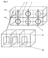
- Air outlet openings are also arranged on the fresh air supply lines 1.1, 1.2 and are connected to pieces of piping pants.
- the mixed air outlet openings of the respective pipe trousers end in the floor area of the office floor above.
- the fresh air outlet flaps 3, 4 assigned to them are regulated as a function of temperature regulators in the office space via the adjustment mechanisms 10 connected to the respective common axes 9 for the closure flaps so that the fresh air temperature at the various mixed air outlet openings is between 22 ° C. and 28 ° C.
- goods are in a warehouse for fresh vegetables different requirements for the optimal storage temperature.
- a total of three are located directly on one side wall of the warehouse pipelines 1.1, 1.2, 11 laid side by side with rectangular Cross-section.
- Two of these lines are as fresh air supply lines 1.1, 1.2 laid so that they are in contact with the outside air.
- These two Fresh air supply lines 1.1, 1.2 are equipped with fans that Suck in fresh air and into the downstream fresh air supply line 1.1, 1.2 promote.
- One of the two fresh air supply lines 1.1 is also connected to a cooling unit, with the help of which the fresh air in this fresh air supply line 1.1 reaches a temperature of approximately 0 ° C.
- This fresh air supply line 1.1 is also equipped with a heat-insulating sheath, so that the cooling air generated is also available at the air outlet openings of this fresh air supply line 1.1 without any significant change.
- the third pipeline is only in the hall area and is equipped as a common fresh air mixing box 11 with mixing box partitions 14 in order to be able to guarantee different storage temperatures in different areas of the warehouse.
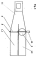
- the sections of the common fresh air mixing box 11 are connected to the two fresh air supply lines 1.1, 1.2, the air outlet openings of the fresh air supply lines 1.1, 1.2, which are located in a common side wall level 2 of these fresh air supply lines 1.1, 1.2, being closed by air outlet flaps 3, 4 can.
- the air outlet flaps 3, 4 rigidly attached to a common axis 9 offset by 89 ° are each controlled with separate adjusting mechanisms 10 so that temperatures between 4 ° C. and 15 ° C. are achieved in the individual areas of the fresh air mixing box.
- the common fresh air mixing box 11 has mixed air outlet openings, with the aid of which the tempered fresh air reaches the individual storage areas.
- the ventilation of a multi-purpose hall is realized by two fresh air supply lines 1.1, 1.2 beginning on an outer wall.
- Both fresh air supply lines 1.1, 1.2 are connected to transport blowers via acoustic insulation backdrops. These blowers each suck in fresh air and generate an overpressure in the fresh air supply lines 1.1, 1.2.
- the first fresh air supply line 1.1 is connected to a heat exchanger, with the aid of which, if necessary, heating is also carried out using the used exhaust air discharged from the multi-purpose hall, or cooling is carried out by coupling with a cooling unit.
- the second fresh air supply line 1.2 is connected to a humidifier or dehumidifier, so that the fresh air available after the humidifier or dehumidifier has a significantly different relative humidity than the untreated fresh air.
- the two fresh air supply lines 1.1, 1.2 end in the immediate vicinity of an outer wall of the multi-purpose hall via a piece of raw pipe in a fresh air mixing box 11, the air outlet openings of the two fresh air supply lines 1.1, 1.2 being equipped with fresh air outlet flaps 3, 4.
- these fresh air outlet flaps 3, 4 are rigidly fixed on a common axis 9, offset by 89 °. This axis 9 is actuated by an adjustment mechanism 10, which in turn is connected to the climate control device of the multi-purpose hall.
- the fresh air mixing box 11 is equipped, in particular in the initial area, with mounting plates which, as static mixing elements, lead to a rapid and homogeneous distribution of the various fresh air components.
- the mixing box 11 is arranged as a branched pipeline with different cross sections in the floor area of the multi-purpose hall. It has mixed air outlet openings for the thermally and moisture-regulated fresh air at regular intervals.
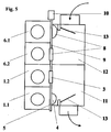
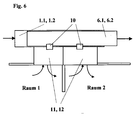
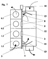
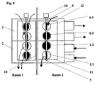
- FIG. 5 to 8 is in a residential building Forced ventilation system installed, consisting of two Fresh air supply lines 1.1, 1.2 and two exhaust air lines 6.1, 6.2 consists. These lines 1.1, 1.2, 6.1, 6.2 are arranged one above the other, that the side walls 2 of the fresh air supply lines 1.1, 1.2 and the Side walls 7 of the exhaust air lines 6.1, 6.2 in a common vertical Level. Both the fresh air supply lines 1.1, 1.2 and Exhaust air ducts 6.1, 6.2 are connected to air conveyors, see above that in the fresh air supply lines 1.1, 1.2 an overpressure and in the Exhaust air lines 6.1, 6.2 each have a negative pressure.
- Fresh air supply and exhaust air lines 1.1, 1.2, 6.1, 6.2 are space-related flap control register with two flaps 3, 4 for each Outlet of untreated and pretreated fresh air as well as two flaps 8 for arranged the entry of the exhaust air into the exhaust air lines 6.1, 6.2.
- the installed exhaust air lines 6.1, 6.2 are assigned to the respective fresh air supply lines 1.1, 1.2 with regard to the balance of the conveyed air quantities.
- the fresh air supply line 1.2 for untreated fresh air is assigned the exhaust air line 6.2 for conveying the exhaust air from essentially untreated used fresh air.
- the flap 3 installed on this fresh air supply line 1.2 is fully opened, only a preset minimum quantity is conveyed from the fresh air supply line 1.1 for thermally pretreated fresh air.
- the completely open flap 4 on the fresh air supply line 1.1 mainly thermally pretreated fresh air enters the room in question.
- flap 8 is now also completely open for the entry of the exhaust air into the exhaust air line 6.1, so that the energy content from the used, thermally pretreated fresh air through the separate discharge in the exhaust air line 6.1 in the sense of a circulating air conveyance to the thermally pretreated Fresh air flow can be transmitted.
- a fresh air mixing box 11 is arranged downstream of the respective flaps 3, 4 for the fresh air outlet.
- the flaps 8 for the entry of the exhaust air into the exhaust air line 6.1, 6.2 are each preceded by an exhaust air collector 12 - seen in the flow direction of the exhaust air.
- Control flaps 13 are installed both in the fresh air mixing boxes 11 and in the exhaust air collectors 12, by means of which stable pressure conditions in the forced-ventilation rooms can be preset.
- the adjustment mechanisms 10 for the common flap axes 9 are connected to the control center of the building. The desired climatic conditions in the individual rooms are achieved by selectively actuating the adjustment mechanisms 10 via these control centers.
Landscapes
- Engineering & Computer Science (AREA)
- Chemical & Material Sciences (AREA)
- Combustion & Propulsion (AREA)
- Mechanical Engineering (AREA)
- General Engineering & Computer Science (AREA)
- Ventilation (AREA)
- Duct Arrangements (AREA)
- Central Air Conditioning (AREA)
Applications Claiming Priority (2)
| Application Number | Priority Date | Filing Date | Title |
|---|---|---|---|
| DE19951810 | 1999-10-27 | ||
| DE19951810 | 1999-10-27 |
Publications (2)
| Publication Number | Publication Date |
|---|---|
| EP1096208A2 true EP1096208A2 (fr) | 2001-05-02 |
| EP1096208A3 EP1096208A3 (fr) | 2003-11-05 |
Family
ID=7927091
Family Applications (1)
| Application Number | Title | Priority Date | Filing Date |
|---|---|---|---|
| EP00123527A Withdrawn EP1096208A3 (fr) | 1999-10-27 | 2000-10-27 | Dispositif de ventilation des pièces d' installations collectrice d'air d' un bâtiment avec système de gaines et procédé d' utilisation correspondant |
Country Status (2)
| Country | Link |
|---|---|
| EP (1) | EP1096208A3 (fr) |
| DE (1) | DE10053509A1 (fr) |
Cited By (3)
| Publication number | Priority date | Publication date | Assignee | Title |
|---|---|---|---|---|
| NL1033393C2 (nl) * | 2007-02-14 | 2009-12-08 | Klimaatgroep Holland B V | Ventilatiesysteem en samengestelde klep voor een dergelijk systeem. |
| WO2012103979A1 (fr) * | 2011-02-04 | 2012-08-09 | Albert Bauer | Procédé permettant de faire fonctionner un système de ventilation présentant une chambre de mélange |
| CN108917077A (zh) * | 2018-06-01 | 2018-11-30 | 黑龙江双兴医用净化工程有限公司 | 洁净室模块化吊顶层流净化机组 |
Families Citing this family (2)
| Publication number | Priority date | Publication date | Assignee | Title |
|---|---|---|---|---|
| DE10202760A1 (de) | 2002-01-24 | 2003-08-14 | Trw Automotive Electron & Comp | Baugruppe bestehend aus Gehäuse und Klappeneinheit |
| CN112628979B (zh) * | 2020-12-04 | 2022-07-19 | 珠海格力电器股份有限公司 | 一种新风量切换旋转式装置及空调器 |
Citations (1)
| Publication number | Priority date | Publication date | Assignee | Title |
|---|---|---|---|---|
| WO1998003006A1 (fr) | 1996-07-16 | 1998-01-22 | At & T Corp. | Systeme et procede de mise a jour d'un acheminement dans un reseau au moyen d'une recherche integree bidirectionnelle interreseau |
Family Cites Families (4)
| Publication number | Priority date | Publication date | Assignee | Title |
|---|---|---|---|---|
| US4164976A (en) * | 1974-10-30 | 1979-08-21 | Timmerman Engineers, Inc. | Damper assembly |
| DE2807901C3 (de) * | 1978-02-24 | 1994-04-14 | Ltg Lufttechnische Gmbh | Steuervorrichtung zur Steuerung eines Zuluftstromes und eines Abluftstromes |
| DE7820323U1 (de) * | 1978-07-06 | 1978-10-19 | Gebrueder Trox Gmbh, 4133 Neukirchen- Vluyn | Deckenluftauslass fuer klimaanlagen |
| US4312381A (en) * | 1980-03-27 | 1982-01-26 | Aladdin Heating Corporation | Air flow damping system |
-
2000
- 2000-10-27 EP EP00123527A patent/EP1096208A3/fr not_active Withdrawn
- 2000-10-27 DE DE10053509A patent/DE10053509A1/de not_active Withdrawn
Patent Citations (1)
| Publication number | Priority date | Publication date | Assignee | Title |
|---|---|---|---|---|
| WO1998003006A1 (fr) | 1996-07-16 | 1998-01-22 | At & T Corp. | Systeme et procede de mise a jour d'un acheminement dans un reseau au moyen d'une recherche integree bidirectionnelle interreseau |
Cited By (8)
| Publication number | Priority date | Publication date | Assignee | Title |
|---|---|---|---|---|
| NL1033393C2 (nl) * | 2007-02-14 | 2009-12-08 | Klimaatgroep Holland B V | Ventilatiesysteem en samengestelde klep voor een dergelijk systeem. |
| WO2012103979A1 (fr) * | 2011-02-04 | 2012-08-09 | Albert Bauer | Procédé permettant de faire fonctionner un système de ventilation présentant une chambre de mélange |
| CN103492813A (zh) * | 2011-02-04 | 2014-01-01 | 罗伯特·博世有限公司 | 用于运行具有混合室的通风设备的方法 |
| AU2011358211B2 (en) * | 2011-02-04 | 2017-06-22 | Robert Bosch Gmbh | Method for operating a ventilation system with a mixing chamber |
| US9759443B2 (en) | 2011-02-04 | 2017-09-12 | Robert Bosch Gmbh | Method for operating a ventilation system with a mixing chamber |
| CN103492813B (zh) * | 2011-02-04 | 2017-10-20 | 罗伯特·博世有限公司 | 用于运行具有混合室的通风设备的方法 |
| CN108917077A (zh) * | 2018-06-01 | 2018-11-30 | 黑龙江双兴医用净化工程有限公司 | 洁净室模块化吊顶层流净化机组 |
| CN108917077B (zh) * | 2018-06-01 | 2021-06-29 | 黑龙江双兴医用净化工程有限公司 | 洁净室模块化吊顶层流净化机组 |
Also Published As
| Publication number | Publication date |
|---|---|
| EP1096208A3 (fr) | 2003-11-05 |
| DE10053509A1 (de) | 2001-05-03 |
Similar Documents
| Publication | Publication Date | Title |
|---|---|---|
| EP1509738B1 (fr) | Procede de chauffage et de refroidissement d'une piece et d'un batiment comprenant plusieurs pieces | |
| DE102011002734B4 (de) | Regelverfahren für eine Lüftungsvorrichtung mit Lüftungsvorrichtung | |
| DE102021129210B4 (de) | Einrichtung zur Gebäudelüftung und Verfahren zur Regelung der Zirkulation von Raumluft sowie Regelungseinheit und Computerprogramm hierzu | |
| DE19809974B4 (de) | Gebäude mit Klimatisierung | |
| EP1096208A2 (fr) | Dispositif de ventilation des pièces d' installations collectrice d'air d' un bâtiment avec système de gaines et procédé d' utilisation correspondant | |
| EP2250444B1 (fr) | Système de climatisation à deux canaux, pour la climatisation flexible d un certain nombre de locaux | |
| EP0184887A1 (fr) | Dispositif de ventilation pour bâtiments, en particulier pour appartements conçus sans courants d'air | |
| WO1993023351A1 (fr) | Dispositif de compostage comprenant plusieurs reacteurs separes et un dispositif d'aeration central | |
| EP4206552A1 (fr) | Appareil d'aération | |
| DE212020000567U1 (de) | Gesteuertes mechanisches Ventilationssystem mit Luftmischeinheit | |
| EP1619449B1 (fr) | Appareil de ventilation pour chauffer, refroidir et/ou ventiler une pièce | |
| DE2807901C3 (de) | Steuervorrichtung zur Steuerung eines Zuluftstromes und eines Abluftstromes | |
| DE3242215A1 (de) | Injektor-raumklimageraet | |
| DE3407458C2 (fr) | ||
| EP3425300B1 (fr) | Procédé de climatisation d'un bâtiment et bâtiment avec dispositif de mise en oeuvre dudit procédé | |
| EP4269889B1 (fr) | Système de ventilation pour un bâtiment | |
| DE202004011906U1 (de) | Lufttechnische Einrichtung und Verfahren zum Heizen, Kühlen und/oder Belüften eines Raumes | |
| EP4269890B1 (fr) | Méthode et système de régulation thermique d'un bâtiment | |
| AT508645B1 (de) | Wohnraumlüftungsanlage | |
| EP4357689B1 (fr) | Système et procédé de libération de fumée d'une liaison d'accès verticale d'un bâtiment à plusieurs étages | |
| DE102019127414B4 (de) | Wegeventil | |
| DE2839041A1 (de) | Lufttechnische anlage | |
| DE4444842C1 (de) | Verfahren und Vorrichtung zum Regeln von Luftfeuchtigkeit und -temperatur in Klimaräumen | |
| DE202022001765U1 (de) | Vorrichtung für die Be- und Entlüftung eines Innenraums | |
| EP0990858A2 (fr) | Installation pour la ventilation, le chauffage, et/ou le refroidissement d' au moins un local |
Legal Events
| Date | Code | Title | Description |
|---|---|---|---|
| PUAI | Public reference made under article 153(3) epc to a published international application that has entered the european phase |
Free format text: ORIGINAL CODE: 0009012 |
|
| AK | Designated contracting states |
Kind code of ref document: A2 Designated state(s): AT BE CH CY DE DK ES FI FR GB GR IE IT LI LU MC NL PT SE |
|
| AX | Request for extension of the european patent |
Free format text: AL;LT;LV;MK;RO;SI |
|
| PUAL | Search report despatched |
Free format text: ORIGINAL CODE: 0009013 |
|
| AK | Designated contracting states |
Kind code of ref document: A3 Designated state(s): AT BE CH CY DE DK ES FI FR GB GR IE IT LI LU MC NL PT SE |
|
| AX | Request for extension of the european patent |
Extension state: AL LT LV MK RO SI |
|
| RIC1 | Information provided on ipc code assigned before grant |
Ipc: 7F 24F 13/14 B Ipc: 7F 24F 13/04 A |
|
| AKX | Designation fees paid |
Designated state(s): AT BE CH CY DE DK ES FI FR GB GR IE IT LI LU MC NL PT SE |
|
| STAA | Information on the status of an ep patent application or granted ep patent |
Free format text: STATUS: THE APPLICATION IS DEEMED TO BE WITHDRAWN |
|
| 18D | Application deemed to be withdrawn |
Effective date: 20040504 |