EP1096416B2 - Verfahren zum Wiederaufbau eines Streifenkodes durch aufeinanderfolgende Abtastungen - Google Patents
Verfahren zum Wiederaufbau eines Streifenkodes durch aufeinanderfolgende Abtastungen Download PDFInfo
- Publication number
- EP1096416B2 EP1096416B2 EP99830678.1A EP99830678A EP1096416B2 EP 1096416 B2 EP1096416 B2 EP 1096416B2 EP 99830678 A EP99830678 A EP 99830678A EP 1096416 B2 EP1096416 B2 EP 1096416B2
- Authority
- EP
- European Patent Office
- Prior art keywords
- wave form
- wave
- points
- wave forms
- forms
- Prior art date
- Legal status (The legal status is an assumption and is not a legal conclusion. Google has not performed a legal analysis and makes no representation as to the accuracy of the status listed.)
- Expired - Lifetime
Links
Images




Classifications
-
- G—PHYSICS
- G06—COMPUTING OR CALCULATING; COUNTING
- G06K—GRAPHICAL DATA READING; PRESENTATION OF DATA; RECORD CARRIERS; HANDLING RECORD CARRIERS
- G06K7/00—Methods or arrangements for sensing record carriers, e.g. for reading patterns
- G06K7/10—Methods or arrangements for sensing record carriers, e.g. for reading patterns by electromagnetic radiation, e.g. optical sensing; by corpuscular radiation
- G06K7/14—Methods or arrangements for sensing record carriers, e.g. for reading patterns by electromagnetic radiation, e.g. optical sensing; by corpuscular radiation using light without selection of wavelength, e.g. sensing reflected white light
- G06K7/1404—Methods for optical code recognition
- G06K7/146—Methods for optical code recognition the method including quality enhancement steps
- G06K7/1465—Methods for optical code recognition the method including quality enhancement steps using several successive scans of the optical code
-
- G—PHYSICS
- G06—COMPUTING OR CALCULATING; COUNTING
- G06K—GRAPHICAL DATA READING; PRESENTATION OF DATA; RECORD CARRIERS; HANDLING RECORD CARRIERS
- G06K7/00—Methods or arrangements for sensing record carriers, e.g. for reading patterns
- G06K7/10—Methods or arrangements for sensing record carriers, e.g. for reading patterns by electromagnetic radiation, e.g. optical sensing; by corpuscular radiation
- G06K7/14—Methods or arrangements for sensing record carriers, e.g. for reading patterns by electromagnetic radiation, e.g. optical sensing; by corpuscular radiation using light without selection of wavelength, e.g. sensing reflected white light
Definitions
- the present invention relates to a method for reconstructing a bar code through consecutive scans.
- bar codes are largely used in the automatic identification of products.
- a bar code is made up of a sequence of light and dark areas which are named bar- and space-type elements. These are rectangular-shaped elements, and each of them can have a different amplitude value. The amplitude of the elements is equal to an elementary value called module, or to multiples of it.
- a set of elements univocally represents a character of the code, and a set of characters univocally represents a symbol of a particular code (briefly referred to simply as code).
- code For the purpose of facilitating its location and reading, each code is preceded and followed by quiet zones, that is to say, areas without signs, whose colour corresponds to the background colour on which the bars are printed.
- Each code is defined by a series of rules making up the coding and decoding protocol of that particular type of code. Therefore, a certain sequence of characters matching said protocol represents the decoded symbol of the code being read.
- a typical method can be schematised as follows: a device for reading bar codes lights up the code to be decoded along a reading line; the diffused light is collected by a photo-sensor element which, in its turn, generates an analogue signal that is proportional to the intensity of the diffused light.
- Bar codes are usually examined according to a scan direction which is not coincident with the longitudinal axis of the code; thus, said scan direction usually forms an angle with the longitudinal axis of the bar code. When this angle exceeds a certain value, only a subset of the elements of the code is scanned; thus, the signal relating to said scan is partial, and it does not allow reading the bar code. Having just partial scans, therefore, there is the problem of "reconstructing" a complete scan of the code from said partial scans (or, with an abbreviation largely used in the field, "reconstructing the code").
- known devices carry out a relative movement between the electro-optical acquisition system of the reader and the objects on which the bar codes are.
- the electro-optical acquisition system can be of the fixed type, and the objects can be moved, with respect to it, by a movement system, or the reader can be of the portable type, and be moved over the bar codes by an operator.
- Prior-art reconstruction devices such as those disclosed in U.S. 5,387,787 and EP 0436072 A2 , may be schematised as in figure 2 . They use various algorithms, and they are all based on the composition of the characters or of the code elements.
- the code elements are obtained from the analogue signal, which is obtained by the electro-optical acquisition system, through an operation of digitization.
- Said digitization essentially consists in squaring the analogue signal, which is reduced to only two values (a high and a low value), and in determining the length of the elements.
- the above digitization is a very delicate operation that can generate serious errors in determining the number of elements of the code (by generating errors known as split and merge errors) and in the length of these elements.
- the reconstruction and/or the subsequent decoding of the reconstructed code can be compromised.
- purpose of the present invention is that of realising a method for reconstructing a bar code through consecutive scans to allow a very precise and reliable reconstruction of the code (for its further decoding) with all types of codes, and in particular, with codes whose signals are affected by faults, distortions and reading errors.
- this purpose is achieved by a method for reconstructing a bar code through consecutive scans, said bar code being made up of a plurality of elements having a first and a second reflectivity, comprising the following steps:
- the term "scan” refers to the operation of reading a line through the code. Such operation may be carried out in a number of ways, such as for example illumination with a laser scanner, point by point reading through a photodiode (thus, in a temporal sequence), the contemporaneous illumination of the entire line by a LED and simultaneous global reading through a CCD or C-MOS linear sensor (thus, in a spatial sequence).
- wave form refers to the wave form of the analogue signal emitted by the photo-sensor element, possibly processed, but only so that the x-values of the points of the wave form remain directly connected to the temporal or spatial sequence of the different measurement instants or points during a scan.
- the invention directly operates on the signal of the photo-sensor, before carrying out any digitization of it.
- This is extremely advantageous because the digitization causes a strong reduction in the information contained in the signal, and said reduction is not recoverable in the following steps.
- the above reduction of information content does not directly hinder the decoding of a bar code, but it has been proved that it can be very disadvantageous during the reconstruction; the reconstruction based on the entire signal is much more precise and reliable for it is based on more information. It must also be taken into account that inaccuracies during the reconstruction often generate errors while decoding.
- the aforesaid reconstruction process can be used to combine two or more scans with one another.
- steps (b) and (d) are respectively followed by the following steps:
- said series of points have the same interval, that is to say, each point of the series is separated by an identical distance or by an identical time interval from the following point.
- said series of points are obtained through the sampling of analogue wave forms.
- the number of points provided in each series can be different; preferably, it is of at least 1.5 points for each module of the code to be read. More preferably, it is equal to about 5 points for each module.
- said series of points are values of brightness expressed in grey scales obtained from an image of the bar code, such as that obtainable with a CCD or C-MOS linear sensor.
- the series of points can comprise all the points obtained through the sampling of the analogue wave forms, or preferably, only a subset of them.
- Said subset for example and preferably, can comprise:
- the wave forms can be two-level digitized wave forms, and said series of points can be obtained through the sampling of the two-level digitized wave forms.
- the alignment step comprises the following steps:
- a fundamental aspect of this preferred method is the use of the correlation index; these terms refer to a number which is calculated according to a comparison of the point-by-point values of the wave forms. It can be a distance index, calculated for example as a function of the summation of values function of the step-by-step difference between the values of the two wave forms; alternatively, it can be a proximity index, function of the summation of values function of the step-by-step product between the values of the two wave forms.
- the correlation index it is possible to express the degree of similarity (or of diversity) between the two temporal wave forms with a single numerical value; this approach significantly facilitates the comparisons between wave forms.
- the calculation of the correlation index only considers the values of the two wave forms that are sufficiently close to one another.
- the exclusion from the calculation of the values relating to those points of the wave forms that are too different from one other allows not considering the points that are clearly affected by a reading error in at least one of the wave forms; in fact, the difference of the two wave forms caused by said errors does not influence their alignment.
- the combining step (f) comprises the following steps:
- the selection step (fb) comprises:
- the calculated value can be obtained in different ways.
- the calculated value is an average of the corresponding values of the under construction wave form and of the actual wave form; this calculation can be easily applied whatever the number of actual wave forms considered for the comparison may be.
- the calculated value is chosen through a voting mechanism between the values of the under construction and actual wave forms; this means that the most frequent value among those of the different wave forms is chosen point-by-point. More preferably, the differences between the values relating to corresponding points of the wave forms are calculated two by two, whereas the values differing from the others by more than a fixed tolerance are rejected, and the calculated value is chosen as average of the values not rejected.
- the wave form is a two-level digitized wave form
- the calculated value can be chosen through congruence rules with respect to the code syntax.
- the two-level digitized wave form actually provides the dimensions of the single elements (bar or space) of the code: in fact, a minimum or maximum value in said wave form means a space or bar element those length is proportional to the number of points for which this value remains constant.
- the method of the invention preferably provides for an initial acquisition step wherein said steps a) and b) are-carried out through the following steps:
- the reconstruction process starts when something similar to a code is detected; this means, an area in which the wave form presents significant variations of the reflectivity value (possible portion of code) sided by an area in which the reflectivity value is substantially steady (possible quiet zone).
- the alignment step of the second wave form with the first wave form comprises the following steps:
- the step of recognition of the apparent quiet zones comprises the following steps:
- said correlation index is determined according to what previously said about the fine alignment step.
- Figure 1 schematically shows the reading of a bar code BC by a sequence of scans, referred to as scan1, scan2 ... scanN. This situation occurs, for example, if an object bearing code BC moves on a feeding surface with respect to a fixed reader, or vice versa.
- the figures do not show in detail any reader or electro-optical acquisition system, being this component conventional in itself and essentially not relevant to the invention; thus, it can be of any type, for example of the laser-ray type with photodiode, or of the LED type with CCD or C-MOS.
- An analogue signal 2 is obtained from both electro-optical acquisition systems (see figure 3 ).
- said wave form is given by the temporal (or spatial) sequences of the signal generated by the photodiode as the laser beam passes over the code.
- the data is extracted in sequence (one pixel after the other) from the single sensor elements, so as to obtain again the wave form 2 of figure 3 .
- the following method can advantageously be used in the reconstruction.
- a reader or an electro-optical acquisition system 1 generates an analogue signal 2 over time, on the basis of the collected light and thus, of the reflectivity value of the portion of code (or of non-code) subject to the scan.
- the analogue signal 2 is then sampled by a sampling converter 3, which generates a sampled analogue wave form 4, obtained from the analogue wave form by keeping of it only the points corresponding to fixed instants of sampling.
- the sampling consists of selecting, measuring and storing the luminosity value of the wave form 2 in a series of points of the axis of abscissas.
- a minimum number of sampling points is needed for the sampling to ensure that the sampled wave form can be reconstructed.
- the inventors have found that, for the purposes of the present method for reconstructing the code, the minimum number of points for the sampling is equal to 1.5 points per module. For example, for a code scan of the type 128, containing about eight characters (corresponding to 50 elements and 93 modules), there are about 140 sampling points.
- a preferred number of sampling points is five per module; in this case, in the above example, there are about 460 sampling points.
- the inventors have found that, with 100 sampling points per module, the sampled wave form is substantially equal to the starting analogue wave form.
- the sampled analogue wave form 4 is then transferred to a reconstructor block 5 to reconstruct the code, and then, to a decoding block 6.
- the origin of the axis of abscissas (time or space) for the wave forms 2 and 4 in figure 3 coincides with the beginning of the scan.
- the y-value can be seen as a value of the reflectivity of the point of code (or non-code) being read in that moment.
- Figure 4 shows a reader having an electro-optical acquisition system comprising a linear C-MOS sensor 1'.
- This type of sensor is characterised in that in output it gives a digital signal 4' (representative of the single scan of the bar code), that is to say, each pixel is associated with a number expressing the grey scale of that point, or the luminosity of that point.
- an electro-optical acquisition system of the C-MOS type gives an already sampled analogue signal in output.
- the method of reconstruction starts when two consecutive scans are acquired, a first and a second scan (the latter containing more information), which both present a portion representative of a possible code, and at least one adjoining portion representative of a possible quiet zone. For this purpose, it is possible to determine an area in which the signal presents very limited variations over time, followed or preceded by an area in which, on the contrary, the signal has very marked variations over time, on the further condition that the area having limited variations is sufficiently wide with respect to the difference of position of the variations in the other area.
- very limited means that a verification its carried out with respect to a fixed threshold; for example, it is checked whether the variations in a first area are lower than a certain threshold S1; whether the variations in a second area adjoining the first one are greater than a threshold S2, and whether the extension of the first area is greater than S3 times the temporal distance between any of two consecutive variations of the second area.
- the first and second scans are aligned.
- said alignment can be made in two positions; in fact, the portions of possible code may probably be sided by portions of possible quiet zones at both ends, because often the code has not only the quiet zones (which are compulsory) at its ends, but usually it is also sided by lateral light areas.
- the two ends of the portions of possible code actually is the end of the code, that is to say, it is not previously known which the actual quiet zone is.
- both possible alignments are carried out, that is, by translating the second scan with respect to the first one so as to superimpose first the possible initial quiet zones, and then the possible final quiet zones.
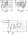
- FIGS. 5a and 5b This operation is schematically shown in figures 5a and 5b .
- Said figures show a first wave form with a continuous line, and a second wave form with a dashed line; it must be noted that the above lines are only simplifications of graphic representation, whereas both the first and the second wave forms are in any case sampled analogue wave forms, thus, made up of a sequence of points,
- the two wave forms are aligned on the left, whereas in figure 5b they are aligned on the right.
- the correct alignment chosen is that to which a correlation index corresponds indicative of a greater similarity between the two wave forms; as it will be explained in the following description, this can be the lower index if it is a distance index, or the greater index if it is a proximity index.
- the correlation index should make you choose the alignment in figure 5a as being the correct one.
- the second wave form is memorised in a memory, and gradually, the results of the following scans are added to it; the wave form "under construction” therein memorised is here called “reconstructed wave form”, while the various wave forms obtained from the following single scans are called “actual wave forms”.
- Figure 6 shows two superimposed wave forms without translation, thus showing that the expected alignment (referred to as DELTAPOS) can be calculated as difference of position of two points of minimum or of maximum; for a more precise calculation, it is possible to consider the average of the values calculated in correspondence of the different points of maximum and minimum.
- DELTAPOS expected alignment
- an acceptability threshold for the correlation index between the two wave forms so as to avoid starting the reconstruction process if the two first and second wave forms are not very similar in their superimposed tract.
- a rough alignment is carried out by translating the actual wave form of DELTAPOS with respect to the reconstructed wave form. If the velocity of the relative movement between object with code and reader is perfectly constant, said rough alignment should in theory be already sufficient to correctly align the two wave forms. Actually, however, this is not true, both because the velocity is never exactly constant, and because of unavoidable measurement inaccuracies. Thus a fine alignment step is then carried out.
- the correlation index can essentially be of two types: a distance index (the higher it is, the more the two wave forms are different) or a proximity index (the higher it is high, the more the two wave forms are similar). In both cases, said index is calculated as summation for all the superimposition points of the two wave forms of values that are function of the respective values of the two wave forms.
- i is the sampling index, and it varies for the entire superimposition area of the two waveforms, so that r i and a i take in sequence all the reflectivity values of the reconstructed wave form and of the actual wave form respectively;
- n is the number of the sampled points comprised in the superimposition interval;
- j is the variable standing for the 2M+1 alignments for which the distance index is calculated;
- p is an integer.
- the points for which the two wave forms present clearly different values (that is to say, have a greater difference than the fixed tolerance, determined at the initial alignment step or otherwise) are not considered into the calculation; in fact, this eventuality is a sign of a reading error, and it is preferable that it has no weight in the evaluation of the alignment conditions.
- three areas are determined: an initial area of the reconstructed wave form to which no area of the actual wave form corresponds; a central superimposition area, and a final area of the actual wave form to which no area of the reconstructed wave form corresponds.
- the reconstructed wave form is updated as follows: it remains unaltered in the initial area (that is to say, the data is definitively acquired); in the final area, the reconstructed wave form remains equal to the actual wave form; in the central superimposition area, the reconstructed wave form is updated with values that are function of the values taken, point-by-point, by the two wave forms in said area.
- This function can be of different types. For example, it is simply possible to make a step-by-step measurement of the average of the values of the two wave forms, or to take one (maximum or minimum) of the two values. This approach is certainly valid in the case of high-quality printed codes that are clearly, read, without reflections or other faults. In fact, the two portions of wave forms will be very similar to one another.
- the reconstruction method is effective in the presence of reading errors, it is preferable to use not just one but several actual wave forms. Each of them will be aligned with the wave form established as explained above, after which, comparison and selection are carried out through a voting mechanism between the values of the reconstructed and actual wave forms.
- the expression "voting mechanism" means that for each point, the values of the different wave forms are compared with one another. Those having little difference with one another (less than the fixed tolerance threshold) are regarded as being equal; thus, the most frequent value is searched and adopted.
- voting mechanism means that for each point, the values of the different wave forms are compared with one another. Those having little difference with one another (less than the fixed tolerance threshold) are regarded as being equal; thus, the most frequent value is searched and adopted.
- the number of actual wave forms considered is even and therefore, the overall number of wave forms (reconstructed plus actual wave forms) is odd. In case, it is also possible to match a voting mechanism with some averages so as to average results that are almost equal with one another.
- analogue wave form is localised first, that is to say, the beginning and the end of a part of the code are found in the scan.
- the localiser can be a simple digitizer or else.
- the first wave form (for example, the one referring to scan1) is sent on several delay lines (RIT1, RIT2, ... RITn) placed in parallel. Each delay line delays the first wave form by increasing units of time (1, 2, ... n). All delayed wave forms are compared with the second wave form (belonging, for example, to scan2) by operational amplifiers A1, A2, ... An.
- the operational amplifiers are provided in output with blocks S1, S2, ... Sn, which calculate a correlation index between the two wave forms according to the same formulas 1-4 already described. As in this case the wave forms are continuous quantities, the summations become integrals.
- the block S giving the minimum (or maximum) output indicates which of the delayed wave forms is aligned (for example, scan1 + RIT3) with the second wave form. With this operation, the wave forms have been aligned and the DELTAPOS has been calculated (in the example, it is RIT3).
- the two scans must be combined.
- the indications of the two localisers are used.
- the first localiser gives the point where the reconstructed wave form begins, while the second localiser gives the point where the actual wave form ends.
- the two wave forms are put together.
- DELTAPOS has been calculated, from the third scan on it is possible to carry out a rough alignment with DELTAPOS. Also in this case, a fine alignment step may follow.
- the forward and backward steps of the two wave forms are obtained by some delays to one wave form or to the other.
- a reader or electro-optical acquisition system 11 generates an analogue signal over time 12, that is function of the collected light and thus of the reflectivity value of the portion of code (or of non-code) subject to the scan.
- the analogue signal 12 is then digitized by a digitizer 13 and then sampled by a sampler 15, thus generating a two-level digital wave form 14, obtained from the analogue wave form by maintaining of it only the points corresponding to fixed sampling instants and normalising the y-values (the reflectivity values) only onto two levels, minimum and maximum.
- the broken continuous line of the two-level digital wave form is just a simplification of drawing; in fact, said wave form is in any case made up of a sequence of points, placed on the minimum or on the maximum level, each corresponding to an x-point which is equal to the sampling instant.
- the sampled two-level digital wave form 14 is then transferred to a reconstructor block 16 to reconstruct the characters of the code and then, to a decoding block 17.
- a minimum or maximum value in said wave form means a space or bar element, the length of which is proportional to the number of points for which this value remains constant.
- the number of elements making up each character is known, as well as the number of elements whose length must be equal to one module and the number of elements whose length must be equal to a multiple of the module.
- the synchronism character it is possible to determine the x-interval corresponding to a character on the wave form.
- each character of the code is made up of six elements, four of which are one module long, and two of which are long twice the module (features that are used here only as example, and not corresponding to any real code), it is easy to carry out a selection character by character, rejecting each time those not complying with the congruence; for example, in figure 9 it can be noted that:
- a reader or electro-optical acquisition system 21 generates an analogue signal over time 22, on the basis of the collected light and thus, of the reflectivity value of the portion of code (or of non-code) subject to the scan.
- the analogue signal 22 is first sampled by a sampler 23, and then is processed by a feature extractor 24, which generates a wave form 25, obtained from the sampled analogue wave form by maintaining of it only a subset of characteristic points, such as for example the relative minimum and maximum points.
- Other subsets of characteristic points of the sampled wave form that the feature extractor 24 can extract are, for example, the points in which, the first derivative crosses zero, or the points in which the second derivative crosses zero, or else.
- the broken continuous line of the wave form 25 is just for explanatory purposes; in fact, said wave form is in any case made up only of the sequence of points marked with a dot.
- the wave form 25 is then transferred to a reconstructor block 26 to reconstruct the code, and then, to a decoding block 27.
- i is the sampling index, and it varies for the entire superimposition area of the two wave forms, so that rx i and ax i take in sequence all the time values of the reconstructed wave form and of the actual wave form, respectively, and ry i and ay i take in sequence all the reflectivity values of the reconstructed wave form and of the actual wave form, respectively;
- n is the number of the sampled points comprised in the superimposition interval;
- j is the variable standing for the 2M+1 alignments for which the distance index is calculated.
- the wave form made up of maximums and minimums it is advantageously possible to use procedural steps that consider the greater quantity of information available; in fact, the minimums are connected to bar elements, whereas the maximums are connected to space elements, and the distances between consecutive minimums and maximums are connected to the amplitudes of the elements.
- the wave form made up of maximums and minimums it is possible to apply congruence criteria with respect to the code syntax.
- the code syntax can be deduced by decoding a synchronism character (initial or final) of the code; in addition, by decoding the synchronism character, it is possible to determine the x-interval corresponding to a character on the wave form.
Landscapes
- Engineering & Computer Science (AREA)
- Physics & Mathematics (AREA)
- General Physics & Mathematics (AREA)
- Theoretical Computer Science (AREA)
- Toxicology (AREA)
- Electromagnetism (AREA)
- Artificial Intelligence (AREA)
- Computer Vision & Pattern Recognition (AREA)
- Health & Medical Sciences (AREA)
- General Health & Medical Sciences (AREA)
- Quality & Reliability (AREA)
- Character Discrimination (AREA)
- Measurement Of The Respiration, Hearing Ability, Form, And Blood Characteristics Of Living Organisms (AREA)
- Image Input (AREA)
- Optical Transform (AREA)
- Investigating Or Analysing Biological Materials (AREA)
- Image Processing (AREA)
Claims (26)
- Verfahren zur Rekonstruktion eines Strichcodes durch aufeinanderfolgende Abtastungen, wobei der Strichcode aus einer Mehrzahl von Elementen besteht, die eine erste und eine zweite Reflektivität aufweisen, wobei das Verfahren die folgenden Schritte umfasst:a) Durchführen mindestens einer Abtastung des Strichcodes;b) Ermitteln einer zu konstruierenden Wellenform, die für die mindestens eine Abtastung repräsentativ ist;und Ausführen der folgenden Schritte, bis die zu konstruierende Wellenform repräsentativ für den gesamten Strichcode ist:c) Ausführen einer tatsächlichen Abtastung des Strichcodes;d) Ermitteln einer tatsächlichen Wellenform, die für die tatsächliche Abtastung repräsentativ ist;e) Ausrichten der zu konstruierenden und der tatsächlichen Wellenform;f) Kombinieren der ausgerichteten Wellenformen, indem die zu konstruierende Wellenform mit der tatsächlichen Wellenform aktualisiert wird,wobei sowohl die zu konstruierende Wellenform als auch die tatsächliche Wellenform eine gesampelte analoge Wellenform sind oder beide eine gesampelte Wellenform von Luminositätswerten sind, die in Graustufen ausgedrückt sind, oder beide eine Untergruppe von Punkten einer gesampelten analogen Wellenform oder eine Untergruppe von Punkten einer gesampelten Wellenform von Luminositätswerten sind, die in Graustufen ausgedrückt sind.
- Verfahren nach Anspruch 1, bei dem den Schritten (b), (d) jeweils die folgenden Schritte folgen:b') Ermitteln einer ersten Serie von Punkten auf der zu konstruierenden Wellenform;d') Ermitteln einer zweiten Serie von Punkten auf der tatsächlichen Wellenform.
- Verfahren nach Anspruch 2, bei dem die Serien von Punkten alle denselben Abstand haben.
- Verfahren nach Anspruch 2, bei dem mindestens 1,5 Punkte für ein jedes Modul des Strichcodes in der Serie von Punkten vorgesehen sind.
- Verfahren nach Anspruch 4, bei dem ungefähr 5 Punkte für ein jedes Modul des Strichcodes in der Serie von Punkte vorgesehen sind.
- Verfahren nach Anspruch 2, bei dem die Serien von Punkten erhalten werden, indem analogen Wellenformen gesampelt werden.
- Verfahren nach Anspruch 2, bei dem die Serien von Punkten durch Luminositätswerte gebildet werden, die in Graustufen ausgedrückt sind und aus einem Bild des Strichcodes erhalten werden.
- Verfahren nach Ansprüchen 6 und 7, bei dem die Serien von Punkten eine Untergruppe der Punkte sind, die durch das Sampeln von analogen Wellenformen erhalten werden.
- Verfahren nach Anspruch 8, bei dem die Serien von Punkten durch eines der Folgenden gebildet werden:- die Maximal und Minimal der Punkte, die durch das Sampeln der analogen Wellenformen erhalten werden;- die Nullstellen der ersten Ableitungen der analogen Wellenformen; oder- die Nullstellen der zweiten Ableitung der analogen Wellenformen.
- Verfahren nach einem der Ansprüche 1 bis 9, bei dem der Schritt (e) des Ausrichtens die folgenden Schritte umfasst:- Vorhersagen einer erwarteten Ausrichtung;- Ausführen einer groben Translation zwischen der zwei Wellenformen auf Grundlage der erwarteten Ausrichtungen;- Berechnen eines Korrelationsindex der zwei Wellenformen;- Ausführen einer feinen Translation aus einer feststehenden Anzahl (M) von Schritten zwischen den beiden Wellenformen in beide Richtungen;- Berechnen des Korrelationsindex für eine jede feine Translation;- Ermitteln desjenigen Index unter den berechneten Korrelationsindizes, der indikativ für die minimale Differenz zwischen den beiden Wellenform ist;- Ausrichten der zwei Wellenformen auf Grundlage der feinen Translation, der der ermittelte Korrelationsindex entspricht;- Aktualisieren des erwarteten Ausrichtungswertes auf Grundlage der obigen feinen Ausrichtung.
- Verfahren nach Anspruch 10, bei dem der Korrelationsindex ein Abstandsindex ist, der als Funktion der Summation einer Wertefunktion ("values function") des Punkt-zu-Punkt-Abstandes zwischen den Werten der zwei Wellenformen berechnet wird.
- Verfahren nach Anspruch 6 und Anspruch 11, bei dem der Abstandsindex nach einer der folgenden Formeln berechnet wird:


- Verfahren nach Anspruch 9 und Anspruch 11, bei dem der Abstandsindex nach einer der folgenden Formeln berechnet wird:


- Verfahren nach Anspruch 10, bei dem der Korrelationsindex ein Nahheitsindex ist, der als Funktion der Summierung von einer Wertefunktion des Punkt-für-Punkt-Produktes zwischen den Werten der zwei Wellenformen berechnet wird.
- Verfahren nach Anspruch 6 und Anspruch 14, bei dem der Nahheitsindex gemäß der folgenden Formel berechnet wird:

- Verfahren nach einem der Ansprüche 10 bis 15, bei dem die Berechnung des Korreiationsindex nur diejenigen Werte der zwei Wellenformen berücksichtigt, die ausreichend dicht beieinander liegen.
- Verfahren nach Anspruch 1, bei dem der Kombinationsschritt (f) die folgenden Schritte umfasst:fa) Ermitteln eines zentralen Überlagerungsbereichs zwischen der ausgerichteten zu konstruierenden Wellenform und der tatsächlichen Wellenform, eines Anfangsbereichs, in dem nur die zu konstruierende Wellenform vorliegt, und eines Endbereichs, in dem nur die tatsächliche Wellenform vorliegt,fb) Auswählen der zu konstruierenden und/oder der tatsächlichen Wellenform Bereich für Bereich;fc) Aktualisieren der zu konstruierenden Wellenform auf Grundlage der ausgewählten Wellenform.
- Verfahren nach Anspruch 17, bei dem der Auswahlschritt fb Folgendes umfasst:- Punkt-für-Punkt-Auswahl des Wertes der zu konstruierenden Wellenform in dem Anfangsbereich;- Punkt-für-Punkt-Auswahl eines Wertes, der auf Grundlage der zugehörigen Werte der zu konstruierenden Wellenform und der tatsächlichen Wellenform berechnet wurde, in dem zentralen Überlagerungsbereich;- Punkt-für-Punk-Auswahl des Wertes der tatsächlichen Wellenform in dem Endbereich.
- Verfahren nach Anspruch 18, bei dem der berechnete Wert ein Durchschnittswert der entsprechenden Werte der zu konstruierenden Wellenform und der tatsächlichen Wellenform ist.
- Verfahren nach Anspruch 18, bei dem mindestens zwei tatsächliche Wellenformen gespeichert werden und der berechnete Wert in einer Abstimmung zwischen den Werten der zu konstruierenden Wellenform und der tatsächlichen Wellenform gewählt wird.
- Verfahren nach Anspruch 18, bei dem die Unterschiede zwei-zu-zwei zwischen den Werten berechnet werden, die sich auf die korrespondierenden Punkte der Wellenformen beziehen; wobei die Werte, die von den anderen um mehr als eine vorbestimmte Toleranz abweichen, zurückgewiesen werden und der berechnete Wert als Durchschnitt der nichtzurückgewiesenen Werte gewählt wird.
- Verfahren nach Anspruch 9 und Anspruch 18, bei dem der berechnete Wert durch Kongruenzregeln bezüglich der Syntax des Codes gewählt wird.
- Verfahren nach Anspruch 10, umfassend einen anfänglichen Erfassungsschritt, in dem Schritte a) und b) durch die folgenden Schritte ausgeführt werden:- Suchen zweier aufeinanderfolgender Wellenformen, bei denen ein Bereich vorliegt, der repräsentativ für einen Endabschnitt eines Codes sein kann, dem eine mögliche Ruhezone vorangeht und/oder folgt;- Erfassen der Wellenform als erste und zweite Wellenform;- Ausrichten der zweiten Wellenform mit der ersten Wellenform;- Ermitteln eines Überlagerungsbereichs zwischen der zweiten Wellenform und der ersten Wellenform;- Ausführen einer anfänglichen Konstruktion der zu konstruierenden Wellenform in dem Überlagerungsbereich mit Daten, die eine Funktion der Daten der ersten Wellenform und der Daten der zweiten Wellenform sind;- Ausführen einer anfänglichen Konstruktion der zu konstruierenden Wellenform in dem Überlagerungsbereich, mit Daten, die eine Funktion der Daten der ersten Wellenform und der Daten der zweiten Wellenform sind;- Ausführen einer anfänglichen Konstruktion der zu konstruierenden Wellenform in dem Bereich, der dem Überlagerungsbereich folgt, mit Daten der zweiten Wellenform;- Ausführen einer anfänglichen Berechnung der erwarteten Ausrichtung auf Grundlage der Ausrichtung zwischen der ersten und der zweiten Wellenform.
- Verfahren nach Anspruch 23, bei dem der Ausrichtungsschritt der zweiten Wellenform mit der ersten Wellenform die folgenden Schritte umfasst:- Erkennen der scheinbaren Ruhezonen der ersten und der zweiten Wellenform;- Ausführen einer groben Translation zwischen den beiden Wellenformen auf Grundlage ihrer jeweiligen scheinbaren Ruhezonen;- Berechnen eines Korrelationsindex der zwei Wellenformen;- Ausführen einer feinen Translation zwischen den beiden Wellenformen aus einer feststehenden Anzahl (M) von Schritten in beide Richtungen;- Berechnen des Korrelationsindex für eine jede der feinen Translation;- Ermitteln desjenigen Index aus den berechneten Korrelationsindizes, der indikativ für den minimalen Unterschied zwischen den beiden Wellenformen ist;- Ausrichten der beiden Wellenformen auf Grundlage der feinen Translation, der der ermittelte Korrelationsindex entspricht;- Festsetzen des erwarteten Ausrichtungswertes auf Grundlage der obigen feinen Ausrichtung.
- Verfahren nach Anspruch 24, bei dem der Schritt der Erkennung der scheinbaren Ruhezonen die folgenden Schritte umfasst:- Translation der zweiten Wellenform im Bezug auf die erste Wellenform auf Grundlage von zwei jeweiligen möglichen anfänglichen Ruhezonen;- Berechnen eines Korrelationsindex der beiden Wellenformen;- Translation der zweiten Wellenform bezüglich der ersten Wellenform auf Grundlage der zwei jeweiligen möglichen End-Ruhezonen;- Berechnen eines Korrelationsindex der beiden Wellenformen;- Ermitteln desjenigen Index unter den berechneten Korrelationsindizes, der indikativ für den minimalen Unterschied zwischen den beiden Wellenform ist;- Erkennen derjenigen wahrscheinlichen anfänglichen Ruhezone oder End-Ruhezone als die scheinbare Ruhezone des Codes, die diejenige Translation verursacht hat, der der ermittelte Korrelationsindex entspricht.
- Verfahren nach einem der Ansprüche 24 oder 25, bei dem der Korrelationsindex nach einem der Ansprüche 11 bis 16 ermittelt wird.
Priority Applications (5)
| Application Number | Priority Date | Filing Date | Title |
|---|---|---|---|
| AT99830678T ATE453899T1 (de) | 1999-10-26 | 1999-10-26 | Verfahren zum wiederaufbau eines streifenkodes durch aufeinanderfolgende abtastungen |
| EP99830678.1A EP1096416B2 (de) | 1999-10-26 | 1999-10-26 | Verfahren zum Wiederaufbau eines Streifenkodes durch aufeinanderfolgende Abtastungen |
| DE69941872T DE69941872D1 (de) | 1999-10-26 | 1999-10-26 | Verfahren zum Wiederaufbau eines Streifenkodes durch aufeinanderfolgende Abtastungen |
| US09/631,963 US6688524B1 (en) | 1999-10-26 | 2000-08-03 | Method for reconstructing a bar code through consecutive scans |
| JP2000327690A JP4686752B2 (ja) | 1999-10-26 | 2000-10-26 | 連続走査によりバーコードを復元する方法 |
Applications Claiming Priority (1)
| Application Number | Priority Date | Filing Date | Title |
|---|---|---|---|
| EP99830678.1A EP1096416B2 (de) | 1999-10-26 | 1999-10-26 | Verfahren zum Wiederaufbau eines Streifenkodes durch aufeinanderfolgende Abtastungen |
Publications (4)
| Publication Number | Publication Date |
|---|---|
| EP1096416A1 EP1096416A1 (de) | 2001-05-02 |
| EP1096416B1 EP1096416B1 (de) | 2009-12-30 |
| EP1096416B9 EP1096416B9 (de) | 2010-07-21 |
| EP1096416B2 true EP1096416B2 (de) | 2017-11-22 |
Family
ID=8243647
Family Applications (1)
| Application Number | Title | Priority Date | Filing Date |
|---|---|---|---|
| EP99830678.1A Expired - Lifetime EP1096416B2 (de) | 1999-10-26 | 1999-10-26 | Verfahren zum Wiederaufbau eines Streifenkodes durch aufeinanderfolgende Abtastungen |
Country Status (5)
| Country | Link |
|---|---|
| US (1) | US6688524B1 (de) |
| EP (1) | EP1096416B2 (de) |
| JP (1) | JP4686752B2 (de) |
| AT (1) | ATE453899T1 (de) |
| DE (1) | DE69941872D1 (de) |
Families Citing this family (8)
| Publication number | Priority date | Publication date | Assignee | Title |
|---|---|---|---|---|
| US7354000B2 (en) * | 2005-05-05 | 2008-04-08 | Optoelectronics Co., Ltd. | Method and system for sensing a barcode |
| US20080192004A1 (en) * | 2007-02-08 | 2008-08-14 | Silverbrook Research Pty Ltd | System for scrolling page displayed on a display device |
| US8226007B2 (en) | 2007-03-23 | 2012-07-24 | Ltt, Ltd | Method and apparatus for using a limited capacity portable data carrier |
| CN102034074B (zh) * | 2009-09-25 | 2014-05-14 | 神基科技股份有限公司 | 在图像中定位并撷取条形码区域的图像处理方法及装置 |
| DE202012102113U1 (de) | 2012-06-11 | 2012-07-03 | Sick Ag | Optoelektronischer Codeleser |
| JP5819925B2 (ja) | 2013-12-25 | 2015-11-24 | ウイングアーク1st株式会社 | コード読取装置およびコード読取用プログラム |
| EP3428834B1 (de) * | 2017-07-12 | 2019-06-12 | Sick AG | Optoelektronischer codeleser und verfahren zum lesen von optischen codes |
| CN107832648A (zh) * | 2017-10-24 | 2018-03-23 | 深圳市丰巢科技有限公司 | 一种基于zxing的连续扫描方法及移动终端 |
Citations (3)
| Publication number | Priority date | Publication date | Assignee | Title |
|---|---|---|---|---|
| US5444231A (en) † | 1992-07-13 | 1995-08-22 | Symbol Technologies, Inc. | Bar code scan stitching |
| DE19504912C2 (de) † | 1995-02-15 | 1998-07-02 | Leuze Electronic Gmbh & Co | Verfahren und Vorrichtung zum Erkennen von Barcode-Symbolen |
| DE19711873A1 (de) † | 1997-03-21 | 1998-09-24 | Sick Ag | Verfahren und Vorrichtung zum Lesen eines Strichcodes |
Family Cites Families (21)
| Publication number | Priority date | Publication date | Assignee | Title |
|---|---|---|---|---|
| US4570057A (en) * | 1981-12-28 | 1986-02-11 | Norand Corporation | Instant portable bar code reader |
| JPS62119684A (ja) * | 1985-11-20 | 1987-05-30 | Hitachi Ltd | バ−コ−ド読取り判別方式 |
| JPS63137386A (ja) * | 1986-11-17 | 1988-06-09 | ライト・シグネイチヤーズ・インコーポレーテツド | 書類の認証システム |
| JPS63263587A (ja) * | 1987-04-22 | 1988-10-31 | Canon Inc | バ−コ−ドリ−ダ |
| US5124538B1 (en) * | 1988-08-26 | 1995-01-31 | Accu Sort Systems Inc | Scanner |
| US5028772A (en) * | 1988-08-26 | 1991-07-02 | Accu-Sort Systems, Inc. | Scanner to combine partial fragments of a complete code |
| JPH02137076A (ja) * | 1988-11-18 | 1990-05-25 | Tokyo Electric Co Ltd | バーコード読取装置 |
| JPH02141889A (ja) * | 1988-11-22 | 1990-05-31 | Eastman Kodatsuku Japan Kk | バーコード読取方法 |
| US5319181A (en) * | 1992-03-16 | 1994-06-07 | Symbol Technologies, Inc. | Method and apparatus for decoding two-dimensional bar code using CCD/CMD camera |
| JPH065548B2 (ja) * | 1989-06-23 | 1994-01-19 | エスエムケイ株式会社 | バーコードリーダの信号処理方法 |
| US5241164A (en) * | 1990-01-05 | 1993-08-31 | Symbol Technologies, Inc. | Method of decoding bar code symbols from partial scans |
| CA2022269A1 (en) * | 1990-01-05 | 1991-07-06 | Theodosios Pavlidis | Method of decoding bar code symbols from partial scans |
| JP2946341B2 (ja) * | 1990-04-11 | 1999-09-06 | 株式会社ニコン | パターン位置検出装置およびパターン位置検出方法 |
| US5196685A (en) * | 1990-05-02 | 1993-03-23 | Eastman Kodak Company | Bar code reader |
| JPH0448392A (ja) * | 1990-06-18 | 1992-02-18 | Fujitsu Ltd | バーコード読み取り装置 |
| JPH04268981A (ja) * | 1991-02-25 | 1992-09-24 | Pfu Ltd | バーコードタッチリーダ |
| JPH04340680A (ja) * | 1991-05-17 | 1992-11-27 | Ricoh Co Ltd | ラスタ走査型バーコードリーダ |
| US5296691A (en) * | 1992-09-14 | 1994-03-22 | Lazerdata Corporation | Scanning device for reconstructing a complete code from scanned segments |
| AU681421B2 (en) * | 1993-09-14 | 1997-08-28 | Symbol Technologies, Inc. | Bar code scan stitching |
| US5965863A (en) * | 1994-03-04 | 1999-10-12 | Welch Allyn, Inc. | Optical reader system comprising local host processor and optical reader |
| US6267293B1 (en) * | 1999-02-22 | 2001-07-31 | Cimatrix | Bar code scanning system and method |
-
1999
- 1999-10-26 AT AT99830678T patent/ATE453899T1/de not_active IP Right Cessation
- 1999-10-26 DE DE69941872T patent/DE69941872D1/de not_active Expired - Lifetime
- 1999-10-26 EP EP99830678.1A patent/EP1096416B2/de not_active Expired - Lifetime
-
2000
- 2000-08-03 US US09/631,963 patent/US6688524B1/en not_active Expired - Lifetime
- 2000-10-26 JP JP2000327690A patent/JP4686752B2/ja not_active Expired - Lifetime
Patent Citations (3)
| Publication number | Priority date | Publication date | Assignee | Title |
|---|---|---|---|---|
| US5444231A (en) † | 1992-07-13 | 1995-08-22 | Symbol Technologies, Inc. | Bar code scan stitching |
| DE19504912C2 (de) † | 1995-02-15 | 1998-07-02 | Leuze Electronic Gmbh & Co | Verfahren und Vorrichtung zum Erkennen von Barcode-Symbolen |
| DE19711873A1 (de) † | 1997-03-21 | 1998-09-24 | Sick Ag | Verfahren und Vorrichtung zum Lesen eines Strichcodes |
Non-Patent Citations (1)
| Title |
|---|
| GRAIG K.H. ET AL: "Reading Between the Lines", NORTH AMERICA TECHNOLOGY, INC., pages: 10, - 114 † |
Also Published As
| Publication number | Publication date |
|---|---|
| ATE453899T1 (de) | 2010-01-15 |
| EP1096416B9 (de) | 2010-07-21 |
| JP2001167226A (ja) | 2001-06-22 |
| DE69941872D1 (de) | 2010-02-11 |
| EP1096416B1 (de) | 2009-12-30 |
| EP1096416A1 (de) | 2001-05-02 |
| US6688524B1 (en) | 2004-02-10 |
| JP4686752B2 (ja) | 2011-05-25 |
Similar Documents
| Publication | Publication Date | Title |
|---|---|---|
| US6015089A (en) | High speed image acquisition system and method of processing and decoding bar code symbol | |
| EP0582911B1 (de) | Verfahren und Vorrichtung zur Erfassung von Strichkoden | |
| US6340119B2 (en) | Techniques for reading two dimensional code, including MaxiCode | |
| US5504319A (en) | Method and system for bar code acquisition | |
| CA2231450C (en) | System and method for reading package information | |
| JPH07200712A (ja) | バーコード読み取りの方法および装置 | |
| JP3526880B2 (ja) | 多解像度機械の読み取り可能な記号 | |
| US6708884B1 (en) | Method and apparatus for rapid and precision detection of omnidirectional postnet barcode location | |
| US6547142B1 (en) | Method of scanning indicia using selective sampling | |
| JPH0276087A (ja) | バーコード読み取り技術 | |
| US5566245A (en) | The performance of a printer or an imaging system using transform-based quality measures | |
| US4642813A (en) | Electro-optical quality control inspection of elements on a product | |
| EP1096416B2 (de) | Verfahren zum Wiederaufbau eines Streifenkodes durch aufeinanderfolgende Abtastungen | |
| WO1998039727A2 (en) | Symbology scanning system for efficiently locating coded symbologies | |
| WO1998039727A9 (en) | Symbology scanning system for efficiently locating coded symbologies | |
| US5902987A (en) | Apparatus and method of rapidly locating edges of machine-readable symbols or other linear images | |
| US5747823A (en) | Two-dimensional code mark detecting method and apparatus therefor | |
| US10460142B2 (en) | Barcode identification method for improving decoding reliability by correcting image distortion | |
| US4856076A (en) | Binary coding circuit for OCR | |
| EP1450291A1 (de) | Strichcode-Leser, welcher eine Maximalwahrscheinlichkeitsmethode nutzt | |
| EP0825548B1 (de) | Laser-Strichcodeleser für einen Brennstab in einem Siedewasserkernreaktor | |
| WO1996009597A1 (en) | Method and apparatus for detecting and adaptively decoding bar code symbols in continuous images | |
| US20260044697A1 (en) | Method for Decoding a Machine Readable Code | |
| EP0790572B1 (de) | Verfahren zur Auswertung von in Streifencodes enthaltenen Daten | |
| EP0840249A2 (de) | Strichkodeleser |
Legal Events
| Date | Code | Title | Description |
|---|---|---|---|
| PUAI | Public reference made under article 153(3) epc to a published international application that has entered the european phase |
Free format text: ORIGINAL CODE: 0009012 |
|
| AK | Designated contracting states |
Kind code of ref document: A1 Designated state(s): AT BE CH CY DE DK ES FI FR GB GR IE IT LI LU MC NL PT SE |
|
| AX | Request for extension of the european patent |
Free format text: AL;LT;LV;MK;RO;SI |
|
| 17P | Request for examination filed |
Effective date: 20011022 |
|
| AKX | Designation fees paid |
Free format text: AT BE CH CY DE DK ES FI FR GB GR IE IT LI LU MC NL PT SE |
|
| 17Q | First examination report despatched |
Effective date: 20071009 |
|
| GRAP | Despatch of communication of intention to grant a patent |
Free format text: ORIGINAL CODE: EPIDOSNIGR1 |
|
| GRAS | Grant fee paid |
Free format text: ORIGINAL CODE: EPIDOSNIGR3 |
|
| GRAA | (expected) grant |
Free format text: ORIGINAL CODE: 0009210 |
|
| AK | Designated contracting states |
Kind code of ref document: B1 Designated state(s): AT BE CH CY DE DK ES FI FR GB GR IE IT LI LU MC NL PT SE |
|
| REG | Reference to a national code |
Ref country code: GB Ref legal event code: FG4D |
|
| REG | Reference to a national code |
Ref country code: CH Ref legal event code: EP |
|
| REG | Reference to a national code |
Ref country code: IE Ref legal event code: FG4D |
|
| REF | Corresponds to: |
Ref document number: 69941872 Country of ref document: DE Date of ref document: 20100211 Kind code of ref document: P |
|
| RAP2 | Party data changed (patent owner data changed or rights of a patent transferred) |
Owner name: DATALOGIC AUTOMATION S.R.L. |
|
| PG25 | Lapsed in a contracting state [announced via postgrant information from national office to epo] |
Ref country code: SE Free format text: LAPSE BECAUSE OF FAILURE TO SUBMIT A TRANSLATION OF THE DESCRIPTION OR TO PAY THE FEE WITHIN THE PRESCRIBED TIME-LIMIT Effective date: 20091230 Ref country code: FI Free format text: LAPSE BECAUSE OF FAILURE TO SUBMIT A TRANSLATION OF THE DESCRIPTION OR TO PAY THE FEE WITHIN THE PRESCRIBED TIME-LIMIT Effective date: 20091230 |
|
| REG | Reference to a national code |
Ref country code: NL Ref legal event code: VDEP Effective date: 20091230 |
|
| PG25 | Lapsed in a contracting state [announced via postgrant information from national office to epo] |
Ref country code: AT Free format text: LAPSE BECAUSE OF FAILURE TO SUBMIT A TRANSLATION OF THE DESCRIPTION OR TO PAY THE FEE WITHIN THE PRESCRIBED TIME-LIMIT Effective date: 20091230 |
|
| PLBI | Opposition filed |
Free format text: ORIGINAL CODE: 0009260 |
|
| PG25 | Lapsed in a contracting state [announced via postgrant information from national office to epo] |
Ref country code: PT Free format text: LAPSE BECAUSE OF FAILURE TO SUBMIT A TRANSLATION OF THE DESCRIPTION OR TO PAY THE FEE WITHIN THE PRESCRIBED TIME-LIMIT Effective date: 20100430 Ref country code: NL Free format text: LAPSE BECAUSE OF FAILURE TO SUBMIT A TRANSLATION OF THE DESCRIPTION OR TO PAY THE FEE WITHIN THE PRESCRIBED TIME-LIMIT Effective date: 20091230 Ref country code: ES Free format text: LAPSE BECAUSE OF FAILURE TO SUBMIT A TRANSLATION OF THE DESCRIPTION OR TO PAY THE FEE WITHIN THE PRESCRIBED TIME-LIMIT Effective date: 20100410 |
|
| 26 | Opposition filed |
Opponent name: SICK AG Effective date: 20100702 |
|
| PG25 | Lapsed in a contracting state [announced via postgrant information from national office to epo] |
Ref country code: BE Free format text: LAPSE BECAUSE OF FAILURE TO SUBMIT A TRANSLATION OF THE DESCRIPTION OR TO PAY THE FEE WITHIN THE PRESCRIBED TIME-LIMIT Effective date: 20091230 |
|
| PG25 | Lapsed in a contracting state [announced via postgrant information from national office to epo] |
Ref country code: GR Free format text: LAPSE BECAUSE OF FAILURE TO SUBMIT A TRANSLATION OF THE DESCRIPTION OR TO PAY THE FEE WITHIN THE PRESCRIBED TIME-LIMIT Effective date: 20100331 Ref country code: CY Free format text: LAPSE BECAUSE OF FAILURE TO SUBMIT A TRANSLATION OF THE DESCRIPTION OR TO PAY THE FEE WITHIN THE PRESCRIBED TIME-LIMIT Effective date: 20091230 |
|
| PLAX | Notice of opposition and request to file observation + time limit sent |
Free format text: ORIGINAL CODE: EPIDOSNOBS2 |
|
| PG25 | Lapsed in a contracting state [announced via postgrant information from national office to epo] |
Ref country code: DK Free format text: LAPSE BECAUSE OF FAILURE TO SUBMIT A TRANSLATION OF THE DESCRIPTION OR TO PAY THE FEE WITHIN THE PRESCRIBED TIME-LIMIT Effective date: 20091230 |
|
| PLAF | Information modified related to communication of a notice of opposition and request to file observations + time limit |
Free format text: ORIGINAL CODE: EPIDOSCOBS2 |
|
| PG25 | Lapsed in a contracting state [announced via postgrant information from national office to epo] |
Ref country code: MC Free format text: LAPSE BECAUSE OF NON-PAYMENT OF DUE FEES Effective date: 20101031 |
|
| REG | Reference to a national code |
Ref country code: CH Ref legal event code: PL |
|
| PLBB | Reply of patent proprietor to notice(s) of opposition received |
Free format text: ORIGINAL CODE: EPIDOSNOBS3 |
|
| GBPC | Gb: european patent ceased through non-payment of renewal fee |
Effective date: 20101026 |
|
| PG25 | Lapsed in a contracting state [announced via postgrant information from national office to epo] |
Ref country code: CH Free format text: LAPSE BECAUSE OF NON-PAYMENT OF DUE FEES Effective date: 20101031 Ref country code: FR Free format text: LAPSE BECAUSE OF NON-PAYMENT OF DUE FEES Effective date: 20101102 Ref country code: LI Free format text: LAPSE BECAUSE OF NON-PAYMENT OF DUE FEES Effective date: 20101031 |
|
| REG | Reference to a national code |
Ref country code: FR Ref legal event code: ST Effective date: 20110630 |
|
| PG25 | Lapsed in a contracting state [announced via postgrant information from national office to epo] |
Ref country code: GB Free format text: LAPSE BECAUSE OF NON-PAYMENT OF DUE FEES Effective date: 20101026 |
|
| PG25 | Lapsed in a contracting state [announced via postgrant information from national office to epo] |
Ref country code: IE Free format text: LAPSE BECAUSE OF NON-PAYMENT OF DUE FEES Effective date: 20101026 |
|
| PG25 | Lapsed in a contracting state [announced via postgrant information from national office to epo] |
Ref country code: LU Free format text: LAPSE BECAUSE OF NON-PAYMENT OF DUE FEES Effective date: 20101026 |
|
| RAP2 | Party data changed (patent owner data changed or rights of a patent transferred) |
Owner name: DATALOGIC IP TECH S.R.L. |
|
| PUAH | Patent maintained in amended form |
Free format text: ORIGINAL CODE: 0009272 |
|
| STAA | Information on the status of an ep patent application or granted ep patent |
Free format text: STATUS: PATENT MAINTAINED AS AMENDED |
|
| 27A | Patent maintained in amended form |
Effective date: 20171122 |
|
| AK | Designated contracting states |
Kind code of ref document: B2 Designated state(s): AT BE CH CY DE DK ES FI FR GB GR IE IT LI LU MC NL PT SE |
|
| REG | Reference to a national code |
Ref country code: DE Ref legal event code: R102 Ref document number: 69941872 Country of ref document: DE |
|
| PGFP | Annual fee paid to national office [announced via postgrant information from national office to epo] |
Ref country code: DE Payment date: 20181019 Year of fee payment: 20 |
|
| PGFP | Annual fee paid to national office [announced via postgrant information from national office to epo] |
Ref country code: IT Payment date: 20181024 Year of fee payment: 20 |
|
| REG | Reference to a national code |
Ref country code: DE Ref legal event code: R071 Ref document number: 69941872 Country of ref document: DE |