EP1096535A2 - Tube cathodique aussi bien que procédé de sa fabrication et appareil de sa fabrication - Google Patents
Tube cathodique aussi bien que procédé de sa fabrication et appareil de sa fabrication Download PDFInfo
- Publication number
- EP1096535A2 EP1096535A2 EP20000402996 EP00402996A EP1096535A2 EP 1096535 A2 EP1096535 A2 EP 1096535A2 EP 20000402996 EP20000402996 EP 20000402996 EP 00402996 A EP00402996 A EP 00402996A EP 1096535 A2 EP1096535 A2 EP 1096535A2
- Authority
- EP
- European Patent Office
- Prior art keywords
- cathode
- ray tube
- temperature
- frit
- blackening
- Prior art date
- Legal status (The legal status is an assumption and is not a legal conclusion. Google has not performed a legal analysis and makes no representation as to the accuracy of the status listed.)
- Withdrawn
Links
Images


Classifications
-
- H—ELECTRICITY
- H01—ELECTRIC ELEMENTS
- H01J—ELECTRIC DISCHARGE TUBES OR DISCHARGE LAMPS
- H01J9/00—Apparatus or processes specially adapted for the manufacture, installation, removal, maintenance of electric discharge tubes, discharge lamps, or parts thereof; Recovery of material from discharge tubes or lamps
- H01J9/38—Exhausting, degassing, filling, or cleaning vessels
- H01J9/385—Exhausting vessels
-
- H—ELECTRICITY
- H01—ELECTRIC ELEMENTS
- H01J—ELECTRIC DISCHARGE TUBES OR DISCHARGE LAMPS
- H01J9/00—Apparatus or processes specially adapted for the manufacture, installation, removal, maintenance of electric discharge tubes, discharge lamps, or parts thereof; Recovery of material from discharge tubes or lamps
- H01J9/02—Manufacture of electrodes or electrode systems
- H01J9/14—Manufacture of electrodes or electrode systems of non-emitting electrodes
- H01J9/142—Manufacture of electrodes or electrode systems of non-emitting electrodes of shadow-masks for colour television tubes
- H01J9/146—Surface treatment, e.g. blackening, coating
Definitions
- the present invention relates to a manufacturing method of a cathode-ray tube, a manufacturing apparatus therefor and a cathode-ray tube.
- FIG. 1 shows a schematic sectional view of a color cathode-ray tube.
- This color cathode-ray tube 10 contains a fluorescent screen (not shown) within a panel portion la of a cathode-ray tube body and a color selecting electrode 3 is disposed with a predetermined gap to this fluorescent screen.
- the color selecting electrode 3 comprises color selecting electrode thin plates 7 containing a lot of tape-like grid structures 5 each having a slit-like electronic beam aperture 4 which selectively allows mainly electron beams to pass through and frames 6 (6a, 6b) for supporting this color selecting electrode thin plates 7.
- the color selecting electrode 3 introduces electron beams R emitted from an electron gun 2 provided in a neck portion 1c of the cathode-ray tube body to the fluorescent screen through the electronic beam apertures 4.
- the panel portion 1a and a funnel portion 1b of the cathode-ray tube body are formed of, for example, glass and both components are joined through a frit portion 8 which is a sealing portion using, for example, frit glass.
- Reference numeral 2a denotes a tip tube provided on a stem of the electron gun 2 for exhausting air and reference numeral 9 denotes a conductive film of carbon film or the like, formed on an inner wall of the funnel portion lb of the cathode-ray tube body.
- the color cathode-ray tube 10 shown in FIG. 1 is produced through predetermined processes. In processes carried out under a relatively high temperature, usually, the following temperature conditions are applied.
- the above three processes are carried out in the order of 1)-3).
- the air-exhausting process is carried out under such a condition that the panel portion la and funnel portion 1b, and, the neck portion 1c and electron gun 2 are sealed.
- the panel portion 1a and funnel portion 1b are sealed by the frit portion 8 usually with frit seal material and the neck portion 1c and electron gun 2 are sealed so as to make an interior of the cathode-ray tube body into an enclosed space.
- the panel portion la and the funnel portion 1b of the cathode-ray tube 10 require strength and air-tightness capable of enduring vacuum under a maximum temperature (less than 400°C) of the exhausting process in order to exhaust air from the cathode-ray tube 10 through the tip tube 2a.
- the panel portion la and the funnel portion lb are sealed using crystal frit glass as a frit sealing agent.
- the crystal frit glass which crystallizes at more than 400°C is used by selecting its material components.
- the frit sealing process is executed at the temperature of about 450°C as described above.
- streak occurs.
- the color selecting electrode 3 assembled so as to match with the position of the panel portion 1a is deformed, so that a color shift may occur in the produced cathode-ray tube.
- the color selecting electrode thin plate 7 fixed to the frame 6 is crept by a certain tension, so that the tension drops by about 30% relative to the initial setting.
- the present invention provides a production method of a cathode-ray tube capable of reducing the temperature in the blackening process and the like and manufacturing a cathode-ray tube whose weight can be reduced, a production apparatus thereof and a cathode-ray tube whose weight can be reduced.
- a vacuum is created in the inside and outside of the cathode-ray tube in an exhaust/sealing process for the cathode-ray tube, so as to exhaust air from the cathode-ray tube.
- the present invention by creating a vacuum in the inside and outside of the cathode-ray tube in the exhausting/sealing process, the difference of pressure between the inside and outside of the cathode-ray tube can be reduced.
- the load applied to the frit portion for joining the panel and funnel can be also reduced.
- the exhaust/sealing unit for the cathode-ray tube includes a means for evacuating the frit portion of the cathode-ray tube from the outside.
- the inside and outside of the frit portion can be evacuated in the exhaust/sealing process. Consequently, by reducing a difference of pressure between the inside and outside of the frit portion, the load applied to the frit portion can be reduced.
- the cathode-ray tube of the present invention is formed by joining the panel and funnel portion with amorphous frit glass.
- the amorphous frit glass possesses a characteristic of adhering to glass materials of the panel and funnel at the temperature of less than 350°C. Therefore, the frit sealing process can be carried out at this relatively low temperature so as to join the panel and funnel.
- the cathode-ray tube of the present invention includes a color selecting electrode subjected to blackening processing under a temperature of less than 350°C.
- the color selecting electrode subjected to the blackening processing under a temperature of less than 350°C is provided.
- the strength of the color selecting electrode may be reduced.
- the present invention concerns a manufacturing method of a cathode-ray tube in which a vacuum is created on the inside and outside of the cathode-ray tube to exhaust air from the cathode-ray tube in the exhaust/sealing process for the cathode-ray tube.
- the present invention concerns a manufacturing apparatus of the cathode-ray tube including a means for creating a vacuum on a frit portion from the outside, in an exhaust/sealing unit for the cathode-ray tube.
- the present invention concerns a cathode-ray tube in which a panel and a funnel are joined with amorphous frit glass.
- the present invention concerns a cathode-ray tube including a color selecting electrode subjected to blackening processing at less than 350°C.
- the effects of A and B can be expected by forming the blackening film.
- the processing temperature does not have to be more than 450°C in order to obtain these effects.
- the electron beam is mechanically cut off by grid structures 5 of the color selecting electrode 3 and at the same time, the electron beams passing through electronic beam apertures 4 between the grid structures 5 is irradiated on the fluorescent screen, so that the electron beams corresponding to signals of R, G, B are irradiated to the fluorescent materials of R, G, B.
- fluorescent material for respective colors are formed so as to match with a position of each grid structure 5 of the color selecting electrode 3, so that the fluorescent screen is constituted.
- this fluorescent screen is produced by attaching or detaching the color selecting electrode 3 for each color.
- the color selecting electrode 3 is subjected to blackening processing so as to generate a creep which will occur in a subsequent process. Then, using the color selecting electrode 3 of that condition, the fluorescent screen is formed.
- the temperature in the blackening process is as high as 450°C and severe for the material.
- the amount of change of tension between before and after the blackening process reaches 30%.
- the color selecting electrode 3 is produced in such a condition that the tension is increased by about 30% and the strength needs to be increased correspondingly to maintain such a high tension.
- the size of a frame 6 is increased so that the weight thereof also increases.
- the reason why the temperature in the blackening process is raised is a temperature condition for the frit sealing process.
- This temperature condition for the frit sealing process is necessary for satisfying a condition for the exhausting process in a subsequent stage.
- the condition of the exhausting process is to keep a strength against a difference of pressure between outside of the cathode-ray tube 10 and atmospheric pressure when air is exhausted from the inside of the cathode-ray tube 10.
- frit seal material of the frit portion 8 needs to have high strength even at such a high temperature.
- the crystal frit glass is stabilized by crystallizing. If the crystal frit glass is employed as the frit sealing material, it is hardened with glass of a panel portion la and a funnel portion 1b by crystallizing so as to keep strength.
- the crystal frit glass whose crystallizing temperature is as low as 350°C for example, is used as the frit sealing material, it cannot keep sufficient strength at 300-400°C in the exhausting process.
- Amorphous frit glass also exists. If this amorphous frit glass is used as the frit sealing material, a working temperature of the frit sealing process is set up so as to keep strength when the frit glass adheres to glasses of the panel portion 1a and funnel portion 1b.
- the working temperature becomes relatively low so that it cannot keep sufficient strength under 300-400°C in the exhausting process.
- the exhausting process must be carried out at a temperature lower than the working temperature of the frit sealing process by 100°C-150°C. In that case, the service life characteristic of the cathode-ray tube cannot be satisfied sufficiently.
- FIGS. 2A, 2B and 3A, 3B Changes of the tension between before and after the blackening process are shown in FIGS. 2A, 2B and 3A, 3B as a result of investigation for every processing temperature in the blackening process.
- FIG. 2A shows the result when the processing temperature is 300°C
- FIG. 2B shows the result when the processing temperature is 350°C
- FIG. 3A shows the result when the processing temperature is 400°C
- FIG. 3B shows the result when the processing temperature is 450°C.
- the X-axis is set in the horizontal direction and a position corresponding to the center of this diagram of the color selecting electrode 3 is set up as a home position.
- Tension (initial) before the blackening process on each X-axis coordinate (relative value) is indicated by ⁇ while tension after the blackening process is indicated by ⁇ .
- FIG. 4 shows relation between the tension utilization ratio and processing temperature.
- the tension utilization ratio is high when the processing temperature is less than 350°C, and if the processing temperature exceeds 350°C, it is indicated that the tension utilization ratio drops suddenly.
- the initial tension can be set to near the tension after the blackening process.
- the structure described above is used, that is a production apparatus for the cathode-ray tube having a means for creating a vacuum on the frit portion of the cathode-ray tube from the outside, provided in the exhaust/sealing unit for the cathode-ray tube so that the temperature of the blackening process can be less than 350°C.
- a vacuum is created inside and outside of the cathode-ray tube in the exhaust/sealing process so as to exhaust air from the cathode-ray tube.
- the frit portion 8 can be joined with amorphous frit glass or crystallizing frit glass which can be crystallized at low temperature and therefore, the temperature of the frit sealing process can be reduced.
- the blackening process temperature for the color selecting electrode 3 can be reduced largely.
- the temperature of the blackening process for the color selecting electrode 3 can be reduced to 300°C + ⁇ .
- FIG. 5 shows a schematic structure diagram of the production apparatus for the cathode-ray tube as an embodiment of the present invention.
- This production apparatus 11 for the cathode-ray tube is employed for producing a color cathode-ray tube 10 shown in FIG. 1, for example.
- This production apparatus 1 has a first vacuum pump 13 which is a means for creating a vacuum in the inside of the cathode-ray tube 10 like the conventional production apparatus.
- This first vacuum pump 13 is connected to a tip tube 2a of an electron gun 2 sealed in a neck portion 1c of the cathode-ray tube 10. As a result, a vacuum can be created in the inside 15 of the cathode-ray tube 10 through the tip tube 2a.
- a processing chamber 12 is provided so as to cover entirely the cathode-ray tube 10 except a part of the neck portion 1c for keeping air-tightness and a second vacuum pump 14 is provided as a means for creating a vacuum on the outside of the cathode-ray tube 10.
- the outside 16 of the cathode-ray tube 10 does not have to be made in a high vacuum state unlike the inside of the cathode-ray tube 10 and may be in a sufficiently low pressure relative to the atmospheric pressure so that there is a small difference of pressure between the inside 15 and outside 16 of the cathode-ray tube 10.
- a working chamber having a heating means for example, a heating furnace 18 is provided so as to cover the cathode-ray tube 10 and the processing chamber 12.
- heating furnace 18 may be used at the same time as a heating furnace for use in other processes like the frit sealing process.
- a structure in which the processing chamber is used as the heating furnace (for example, a heating means such as a heater is provided inside or just outside of the processing chamber) may be employed.
- the color selecting electrode 3 shown in FIG. 1 is subjected to the above described blackening processing under a temperature of less than 350°C.
- a fluorescent surface having a fluorescent layer of a predetermined pattern is formed on an inside face of the panel portion 1a.
- a metal back layer is formed through an intermediate film on the fluorescent screen.
- the color selecting electrode 3 is attached to the panel portion la in which the fluorescent screen and metal back layer are formed on the inside face thereof.
- the panel portion la having the color selecting electrode 3 formed in the above described manner and the funnel portion 1b are prepared.
- the panel portion 1a and the funnel portion 1b are joined together using amorphous frit glass or frit glass (not shown) which is crystallized at less than 350°C for the frit portion 8 as a frit sealing material and the frit sealing process is carried out at a predetermined temperature, for example, 350°C.
- amorphous frit glass or frit glass (not shown) which is crystallized at less than 350°C for the frit portion 8 as a frit sealing material and the frit sealing process is carried out at a predetermined temperature, for example, 350°C.
- organic substances in the fluorescent screen and intermediate film on the inside face of the panel portion 1a are burnt out.
- the cathode-ray tube 10 is cooled gradually to the room temperature.
- the electron gun 2 is inserted into the neck portion Ic of the cathode-ray tube body subjected to frit sealing process and then, the electron gun 2 is sealed by joining glass of the neck portion 1c to the stem of the electron gun 2.
- the cathode-ray tube 10 in which the electron gun 2 is sealed is accommodated in the production apparatus 1 shown in FIG. 5.
- part of the neck portion Ic is exposed from the processing chamber 12 and the tip tube 2a of the exposed stem of the electron gun 2 is connected to the first vacuum pump 13.
- the inside 15 of the cathode-ray tube 10 is evacuated to a pressure of, for example, 0.1 mPa using the first vacuum pump 13.
- the inside 16 of the processing chamber 12 is evacuated to a pressure of, for example, 1 Pa using the second vacuum pump 14.
- the temperature is raised to a predetermined working temperature, for example, 300°C of the exhausting process.
- evacuation of the outside 16 of the cathode-ray tube 10 by the second vacuum pump 14 may be started from a room temperature as described above or may be started during heating. However, to keep strength of the frit glass. the temperature when the evacuation is started must be set up.
- the evacuation is continued until temperature and air is exhausted from the inside 15 of the cathode-ray tube 10 sufficiently.
- the temperature of the inside of the processing chamber 12 is lowered.
- the evacuation of the second vacuum pump 14 is stopped as shown in FIG. 8B to allow leak, so that the inside of the processing chamber 12, that is, the outside 16 of the cathode-ray tube 10 is brought into the atmospheric pressure.
- the cathode-ray tube 10 is taken out of the processing chamber 12 and then, tip-off process is carried out by keeping vacuum in the inside 15 of the cathode-ray tube 10.
- a heater is disposed around a position desired to be sealed of the tip tube 2a and glass of the tip tube 2a is melted by heating by means of the heater. Because the inside 15 of the cathode-ray tube 10 is a vacuum, the molten glass is pulled in and adheres together so as to achieve sealing.
- the cathode-ray tube 10 whose inside 15 is evacuated and sealed, can be produced.
- the frit sealing material of the frit portion 8 which joins together the panel portion la and the funnel portion 1b has sufficient strength, so that it can function as the cathode-ray tube 10.
- a vacuum can be created both at the inside 15 and the outside 16 of the cathode-ray tube 10 by the first vacuum pump 13 and second vacuum pump 14. Therefore, a difference of pressure between the inside and outside of the cathode-ray tube 10 can be made small.
- the load on the frit sealing material of the frit portion 8 can be reduced.
- the amorphous frit glass or frit glass which is crystallized under low temperature of, for example, less than 350°C can be used as a frit sealing material, so that the frit sealing process can be carried out at a low working temperature of, for example, less than 350°C.
- the temperature of the frit sealing process can be reduced.
- the temperature of the blackening process for the color selecting electrode 3, which requires the same or higher temperature as the frit sealing process can be reduced to less than 350°C, for example.
- the change of the tension between before and after the blackening process is reduced largely.
- the initial tension when the color selecting electrode thin plate (color selecting mask) 7 is stretched can be reduced largely as compared to the conventional excessive tension, so that the strength necessary for the frame 6 of the color selecting electrode 3 can be reduced.
- the structure can be simplified by reducing the stiffness of the frame 6, so that the weight of the color selecting electrode can be reduced so as to achieve light weight of the cathode-ray tube.
- the temperatures of the blackening process and frit sealing process are reduced, heating and lighting cost necessary for furnace operation and updating the system and consumption cost of the production apparatus can be reduced, and the time interval of a temperature cycle can be reduced, so that the working efficiency can be improved.
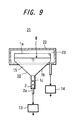
- This embodiment concerns a case in which a means for creating a vacuum on the outside of the cathode-ray tube 10 is provided only near the frit portion 8.
- FIG. 9 shows a schematic structure diagram of the production apparatus for the cathode ray tube according to this embodiment of the present invention.
- the processing chamber 22 covers a portion near the frit portion 8 of the cathode-ray tube 10, that is, part of the funnel portion 1b and panel portion 1a.
- the processing portion 22 is provided only near the frit portion 8, volume of the inside 23 is smaller.
- the difference of pressure between the inside and outside of the cathode-ray tube in the exhaust/sealing process can be reduced. Therefore, the load applied to the frit portion in which the panel and funnel are joined together can be reduced.
- the frit sealing process can be carried out at low working temperatures.
- the temperature of the frit sealing process can be reduced, the temperature of the blackening process for the color selecting electrode can be also reduced.
- the change of tension between before and after the blackening process can be reduced largely.
- the initial tension can be reduced largely as compared to the conventional excessive tension so that the strength necessary for the frame of the color selecting electrode can be also reduced.
- the structure can be simplified by reducing the stiffness of the frame, so that the weight of the color selecting electrode can be reduced thereby leading to reduction in the weight of the cathode-ray tube.
Landscapes
- Engineering & Computer Science (AREA)
- Manufacturing & Machinery (AREA)
- Manufacture Of Electron Tubes, Discharge Lamp Vessels, Lead-In Wires, And The Like (AREA)
- Electrodes For Cathode-Ray Tubes (AREA)
Applications Claiming Priority (2)
| Application Number | Priority Date | Filing Date | Title |
|---|---|---|---|
| JP30717899A JP2001126618A (ja) | 1999-10-28 | 1999-10-28 | 陰極線管の製造方法及び製造装置、並びに陰極線管 |
| JP30717899 | 1999-10-28 |
Publications (1)
| Publication Number | Publication Date |
|---|---|
| EP1096535A2 true EP1096535A2 (fr) | 2001-05-02 |
Family
ID=17965985
Family Applications (1)
| Application Number | Title | Priority Date | Filing Date |
|---|---|---|---|
| EP20000402996 Withdrawn EP1096535A2 (fr) | 1999-10-28 | 2000-10-27 | Tube cathodique aussi bien que procédé de sa fabrication et appareil de sa fabrication |
Country Status (5)
| Country | Link |
|---|---|
| EP (1) | EP1096535A2 (fr) |
| JP (1) | JP2001126618A (fr) |
| KR (1) | KR20010040198A (fr) |
| CN (1) | CN1303115A (fr) |
| TW (1) | TW480540B (fr) |
Cited By (1)
| Publication number | Priority date | Publication date | Assignee | Title |
|---|---|---|---|---|
| US7108573B2 (en) | 2002-10-17 | 2006-09-19 | Canon Kabushiki Kaisha | Sealed container, manufacturing method therefor, gas measuring method, and gas measuring apparatus |
Family Cites Families (4)
| Publication number | Priority date | Publication date | Assignee | Title |
|---|---|---|---|---|
| JPS59149629A (ja) * | 1983-02-14 | 1984-08-27 | Toshiba Corp | 陰極線管の製造方法 |
| JPH08138540A (ja) * | 1994-11-14 | 1996-05-31 | Matsushita Electron Corp | カラー受像管用プレス成型品の製造方法 |
| JPH08293254A (ja) * | 1995-04-24 | 1996-11-05 | Ryuji Ozawa | 小型陰極線管の真空封止 |
| KR100298227B1 (ko) * | 1997-02-14 | 2001-10-24 | 빌.씨. 첸(Bill. C. Chen) | 음극선튜브의진공밀봉방법 |
-
1999
- 1999-10-28 JP JP30717899A patent/JP2001126618A/ja active Pending
-
2000
- 2000-10-19 TW TW89121949A patent/TW480540B/zh not_active IP Right Cessation
- 2000-10-27 EP EP20000402996 patent/EP1096535A2/fr not_active Withdrawn
- 2000-10-27 KR KR1020000063516A patent/KR20010040198A/ko not_active Ceased
- 2000-10-30 CN CN 00133773 patent/CN1303115A/zh active Pending
Cited By (3)
| Publication number | Priority date | Publication date | Assignee | Title |
|---|---|---|---|---|
| US7108573B2 (en) | 2002-10-17 | 2006-09-19 | Canon Kabushiki Kaisha | Sealed container, manufacturing method therefor, gas measuring method, and gas measuring apparatus |
| US7308819B2 (en) | 2002-10-17 | 2007-12-18 | Canon Kabushiki Kaisha | Gas measuring method inside a sealed container |
| US7679279B2 (en) | 2002-10-17 | 2010-03-16 | Canon Kabushiki Kaisha | Image display device having a sealed container with an exhaust pipe |
Also Published As
| Publication number | Publication date |
|---|---|
| KR20010040198A (ko) | 2001-05-15 |
| TW480540B (en) | 2002-03-21 |
| JP2001126618A (ja) | 2001-05-11 |
| CN1303115A (zh) | 2001-07-11 |
Similar Documents
| Publication | Publication Date | Title |
|---|---|---|
| US6129603A (en) | Low temperature glass frit sealing for thin computer displays | |
| US6926575B1 (en) | Method for manufacturing flat image display and flat image display | |
| EP1096535A2 (fr) | Tube cathodique aussi bien que procédé de sa fabrication et appareil de sa fabrication | |
| JPH0343937A (ja) | 映像管の製造法 | |
| US6054805A (en) | Cathode ray tube and method of manufacturing same | |
| US6914378B2 (en) | Color cathode ray tube panel having seal edge corner with a specific curvature | |
| JP2941362B2 (ja) | カラーブラウン管の製造方法 | |
| JPH06203755A (ja) | ブラウン管の製造方法 | |
| KR100512610B1 (ko) | 평면음극선관의 방폭구조 | |
| KR100209612B1 (ko) | 음극선관용 게터 커버 | |
| KR950011248B1 (ko) | 칼라브라운관의 노광방법 및 장치 | |
| KR100283685B1 (ko) | 전계방출표시소자패널의고진공실링방법 | |
| JP3644754B2 (ja) | カラー受像管 | |
| JP2000048725A (ja) | 陰極線管の製造方法 | |
| KR100255673B1 (ko) | 음극선관의 금속막 형성방법 및 이 방법에의해 형성된 금속막을 구비한 음극선관 | |
| JPH0992152A (ja) | カラー陰極線管の製造方法 | |
| WO2006046953A1 (fr) | Procede de traitement thermique d'un tube cathodique | |
| KR20040071443A (ko) | 평면음극선관의 밴드 체결구조 | |
| JPH05190087A (ja) | カラーブラウン管の製造方法 | |
| JPH0696697A (ja) | カラー陰極線管 | |
| JPS6216494B2 (fr) | ||
| JP2001189140A (ja) | 平面ブラウン管の防爆構造 | |
| JPH11213879A (ja) | ブラウン管の製造方法 | |
| JPH03263733A (ja) | 陰極線管の製造方法 | |
| JPH0246621A (ja) | カラー陰極線管の製造方法 |
Legal Events
| Date | Code | Title | Description |
|---|---|---|---|
| PUAI | Public reference made under article 153(3) epc to a published international application that has entered the european phase |
Free format text: ORIGINAL CODE: 0009012 |
|
| AK | Designated contracting states |
Kind code of ref document: A2 Designated state(s): AT BE CH CY DE DK ES FI FR GB GR IE IT LI LU MC NL PT SE |
|
| AX | Request for extension of the european patent |
Free format text: AL;LT;LV;MK;RO;SI |
|
| STAA | Information on the status of an ep patent application or granted ep patent |
Free format text: STATUS: THE APPLICATION IS DEEMED TO BE WITHDRAWN |
|
| 18D | Application deemed to be withdrawn |
Effective date: 20030603 |