EP1100041A2 - Numérisateur d'image optique pour reconnaítre des différents dispositifs de pointage - Google Patents
Numérisateur d'image optique pour reconnaítre des différents dispositifs de pointage Download PDFInfo
- Publication number
- EP1100041A2 EP1100041A2 EP00309832A EP00309832A EP1100041A2 EP 1100041 A2 EP1100041 A2 EP 1100041A2 EP 00309832 A EP00309832 A EP 00309832A EP 00309832 A EP00309832 A EP 00309832A EP 1100041 A2 EP1100041 A2 EP 1100041A2
- Authority
- EP
- European Patent Office
- Prior art keywords
- light ray
- polarized light
- pointing
- pointing instrument
- image
- Prior art date
- Legal status (The legal status is an assumption and is not a legal conclusion. Google has not performed a legal analysis and makes no representation as to the accuracy of the status listed.)
- Withdrawn
Links
Images





Classifications
-
- G—PHYSICS
- G06—COMPUTING OR CALCULATING; COUNTING
- G06F—ELECTRIC DIGITAL DATA PROCESSING
- G06F3/00—Input arrangements for transferring data to be processed into a form capable of being handled by the computer; Output arrangements for transferring data from processing unit to output unit, e.g. interface arrangements
- G06F3/01—Input arrangements or combined input and output arrangements for interaction between user and computer
- G06F3/03—Arrangements for converting the position or the displacement of a member into a coded form
- G06F3/041—Digitisers, e.g. for touch screens or touch pads, characterised by the transducing means
- G06F3/042—Digitisers, e.g. for touch screens or touch pads, characterised by the transducing means by opto-electronic means
-
- G—PHYSICS
- G06—COMPUTING OR CALCULATING; COUNTING
- G06F—ELECTRIC DIGITAL DATA PROCESSING
- G06F3/00—Input arrangements for transferring data to be processed into a form capable of being handled by the computer; Output arrangements for transferring data from processing unit to output unit, e.g. interface arrangements
- G06F3/01—Input arrangements or combined input and output arrangements for interaction between user and computer
- G06F3/03—Arrangements for converting the position or the displacement of a member into a coded form
- G06F3/041—Digitisers, e.g. for touch screens or touch pads, characterised by the transducing means
- G06F3/042—Digitisers, e.g. for touch screens or touch pads, characterised by the transducing means by opto-electronic means
- G06F3/0421—Digitisers, e.g. for touch screens or touch pads, characterised by the transducing means by opto-electronic means by interrupting or reflecting a light beam, e.g. optical touch-screen
- G06F3/0423—Digitisers, e.g. for touch screens or touch pads, characterised by the transducing means by opto-electronic means by interrupting or reflecting a light beam, e.g. optical touch-screen using sweeping light beams, e.g. using rotating or vibrating mirror
-
- G—PHYSICS
- G06—COMPUTING OR CALCULATING; COUNTING
- G06F—ELECTRIC DIGITAL DATA PROCESSING
- G06F3/00—Input arrangements for transferring data to be processed into a form capable of being handled by the computer; Output arrangements for transferring data from processing unit to output unit, e.g. interface arrangements
- G06F3/01—Input arrangements or combined input and output arrangements for interaction between user and computer
- G06F3/03—Arrangements for converting the position or the displacement of a member into a coded form
- G06F3/033—Pointing devices displaced or positioned by the user, e.g. mice, trackballs, pens or joysticks; Accessories therefor
- G06F3/0354—Pointing devices displaced or positioned by the user, e.g. mice, trackballs, pens or joysticks; Accessories therefor with detection of two-dimensional [2D] relative movements between the device, or an operating part thereof, and a plane or surface, e.g. 2D mice, trackballs, pens or pucks
-
- G—PHYSICS
- G06—COMPUTING OR CALCULATING; COUNTING
- G06F—ELECTRIC DIGITAL DATA PROCESSING
- G06F3/00—Input arrangements for transferring data to be processed into a form capable of being handled by the computer; Output arrangements for transferring data from processing unit to output unit, e.g. interface arrangements
- G06F3/01—Input arrangements or combined input and output arrangements for interaction between user and computer
- G06F3/03—Arrangements for converting the position or the displacement of a member into a coded form
- G06F3/033—Pointing devices displaced or positioned by the user, e.g. mice, trackballs, pens or joysticks; Accessories therefor
- G06F3/0354—Pointing devices displaced or positioned by the user, e.g. mice, trackballs, pens or joysticks; Accessories therefor with detection of two-dimensional [2D] relative movements between the device, or an operating part thereof, and a plane or surface, e.g. 2D mice, trackballs, pens or pucks
- G06F3/03545—Pens or stylus
Definitions
- the present invention relates to an optical digitizer, which detects the position coordinates where a finger, a stylus or a pointing stick (hereinafter refer to as a pointing instrument) points on a coordinate plane, and more specifically, to an optical digitizer, which recognizes kinds of pointing instruments and enables an input by a finger or a pen.
- Fig. 1 illustrates an example of the conventional optical digitizers.
- a tunnel mirror 14 is disposed in front of an image forming lens 9 for a linear image sensor 13, and a pair of detecting units, wherein each of the units is arranged in such a manner that a light axis of an LED light source 31 coincides with a light axis of the linear image sensor 13, are arranged in the peripheral area of a coordinate plane 1.
- the tip of a pointing instrument 2, such as a pen is wrapped with a tape 22 composed of a retroreflective material. When a light ray emitted from LED light source 31 is irradiated on the retroreflective tape 22 at the tip of the pen 2, the incident light returns straight back to where it came from due to the retroreflective characteristic.
- the image of this reflected light is taken by the right and left side linear image sensors 13, and converted to an electric signal.
- the signal is then processed at the coordinate computing section 7 by using the triangulation principle to detect the pointed coordinates of the pen tip.
- a hand-touch is allowed.
- an input by a finger cannot be made. Therefore, it cannot be used as a touch pad loaded on a notebook-type personal computer or as a simple touch panel.
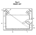
- FIG. 2 Another example of a conventional optical digitizer is illustrated in Fig. 2.
- the retroreflective material is installed at the tip of the pen 2, but in the conventional example illustrated in Fig. 2, the retroreflective material is installed on the frame of the coordinate plane 1.
- the images in the retroreflective material 4 positioned at the two sides of the coordinate plane 1 are taken by each of the right and left image sensors 13.
- the right-side image sensor takes the images 4a and 4b of the retroreflective material
- the left-side image sensor takes the images 4b and 4c, respectively.
- the reflected light from the retroreflective material 4 is intercepted by the pointing instrument 20, and the shadow image 20a is detected by the image sensor 13, which makes it possible to detect the pointed coordinates of the pointing instrument 20.
- a conventional optical digitizer as illustrated in Fig. 1 allowed to input by a special pen only, which requires a pen even for making a simple input through a touch panel. Moreover, since it requires a specific pen, when it is loaded on a notebook-size personal computer, it is often inconvenient for a user.
- the conventional digitizer as illustrated in Fig. 2 served the purpose as far as the inputting by a pen is concerned, but it did not solve the hand-touch problem.
- the present invention aims to provide an optical digitizer, which has the function to recognize kinds of pointing instruments, and enables an input by both a finger and a pen. Moreover, the invention aims to provide an optical digitizer with a pointing instrument equipped with a plurality of functions by installing a supplemental information transmission means into the pointing instrument.
- the present invention relates to an optical digitizer which detects a position coordinate pointed by a pointing instrument on a coordinate plane, and has a function to recognize a first pointing instrument, which is not equipped with a retroreflective material, from a second pointing instrument, which is equipped with the retroreflective material at its tip, wherein the optical digitizer is comprised of a light source for emitting a light ray, an image taking means, which is placed in the periphery of the coordinate plane to take an image of the pointing instrument by using the light ray of the light source and convert the taken image into an electrical signal, a computing means for computing the position coordinates by processing the electrical signal converted by the image taking means, a light polarization means which is provided at the light source for polarizing the emitted light from the light source into a first polarized light or a second polarized light, a switching means with which irradiating light to the coordinate plane is switched to the first polarized light or the second polarized
- the light source means is comprised of two sources, and the polarizing means is comprised of the first polarizing means, which allows the first polarized light to transmit, and the second polarizing means, which allows the second polarized light to transmit, both the polarizing means being installed at each light source, and the first polarized light and the second polarized light are alternately illuminated by irradiating the two light sources alternately through the switching means.
- the polarizing means comprises a first polarizing means, which allows the first polarized light to transmit, and a liquid crystal plate, so that the first polarized light and the second polarized light are illuminated by switching voltages applied to the liquid crystal plate by a switching means.
- the present invention relates to an optical digitizer which has a function to recognize kinds of a pointing instrument
- the optical digitizer is comprised of a light source to emit a light ray, an image taking means, installed in the peripheral area of the coordinate plane to take an image of the pointing instrument by using the light ray of the light source and to convert the taken image into an electrical signal, a calculation means to compute the pointed position coordinates by processing the converted electrical signal through the image taking means, a polarizing means which is installed in the image taking means to make the incident light as the first polarized light or the second polarized light, a dividing means to divide the incident light to the image taking means, a retroreflective material installed at the frame of aforementioned coordinate plane, which has retroreflective characteristics, a polarizing film which is installed in front of the retroreflective material, having a transmitting axis to cause the first polarized light ray to be transmitted, and a judgment means which judges the pointing instrument as a first pointing instrument if the image
- the present invention further relates to an optical digitizer wherein the light source means is comprised of two light sources, further having a third polarizing means to cause the first polarized light to be transmitted, and a fourth polarized means to cause the second polarized light to be transmitted, both of them are installed at each of the two light sources, the optical digitizer further having a switching means to cause the two light sources alternately to be emitted, the second pointing instrument having a liquid crystal material at its tip, the optical digitizer further having a judging means to judge the state of the second pointing instrument in the case where the image of the pointing instrument is taken by the second polarized light, by the polarized light which comes into the image taking means in which the polarized light changes by the voltage applied to the liquid crystal material.
- the first polarized light ray may be a vertically polarized light ray
- the second polarized light ray may be a horizontally polarized light ray
- Fig. 3 is a diagrammatic plane view to show a first embodiment of the optical digitizer in accordance with the present invention
- Fig. 4 is its schematic side view.
- Each detecting unit 3 is comprised of a light source, a linear image sensor 13, a lens 9 to form an image thereon, and a tunnel mirror 14 in which the light axis of the light source and the light axis of the linear image sensor are arranged to coincide.
- a retroreflective material 4 installed at the frame surrounding the coordinate plane 1 is basically the same as the prior art shown in Fig.
- the characteristics of the present invention are that two LEDs 31 and 32 are used as the light source, polarizing films 41, 42 in which polarizing axes are orthogonal therebetween, are provided to the LEDs, and a polarizing film 40 is further installed in front of the retroreflective material 4.
- the detecting units on the right and left are identical in their configuration, so that only one is described and the explanation of the other is omitted.
- the vertically polarizing film 40 which allows vertically polarized light rays to be transmitted
- the vertically polarizing film 41 which allows vertically polarized light rays to be transmitted
- the horizontally polarizing film 42 which allows horizontally polarized light rays to be transmitted
- the tunnel mirror can also employ a half mirror or a pin hole or the like, or it is permissible to arrange the light source and the image sensor at an extremely close distance, thus an appropriate modification can be made.
- the LED 31 is equipped with the vertically polarizing film 41
- the LED 32 is equipped with the horizontally polarizing film 42 respectively, and the light emissions of the LEDs 31 and 32 are switched by a polarized light switching device 35 in order to alternately illuminate the vertically polarized light and the horizontally polarized light on the coordinate plane 1.
- the light ray emitted from the light source enters into the coordinate plane 1 by the tunnel mirror 14.
- the LED 32 is illuminated by the polarized light switching device 35 to cause the horizontally polarized light to enter into the frame of the coordinate plane 1, no image is taken by the image sensor 13 since there is no reflection from the retroreflective material 4 because of the presence of the vertically polarizing film 40 in front of the retroreflective material.
- the LED 31 is illuminated to cause the vertically polarized light to enter into the frame of the coordinate plane 1, the light transmits through the vertically polarizing film 41 and enters into the retroreflective material 4, and returns in the same direction as the direction in which the light came from, so that at each of the image sensors 13 at the right and the left, the image of the retroreflective material positioned at two sides of the coordinate plane 1 is reflected.
- the right image sensor the images of the retroreflective materials 4a and 4b are taken
- the left image sensor the images of the retroreflective materials 4b and 4c are taken, respectively.
- the microprocessor in a coordinate computing section 7 will determine the two dimensional coordinates (X, Y) by using the triangulation principle.
- the pointing instrument judging section 8 judges whether the pointing instrument is a finger or a pen from the state of the polarization switching device 35 and the taken image signals. In other words, in the case where the image of the pointing instrument is taken by the sensor 13 when the vertically polarized light ray is illuminated, the finger 20, and in the case where the image of the pointing instrument is taken by the image sensor 13 when the horizontally polarized light ray is illuminated, then it is judged as the pen 2.
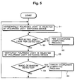
- Fig. 5 shows a flow chart to explain the operation of the first embodiment of the optical digitizer in accordance with the present invention as illustrated in Fig. 3.
- the polarized light switching device 35 is switched to cause the LED 32 to emit light that illuminates the horizontally polarized light rays (Step S1).
- the checking is made whether the reflected light from the retroreflective material 22 installed at the tip of the pen 2 is detected or not (Step S2).
- the pen coordinate computing process is conducted (Step S5), the pointed position coordinates of the pen are detected, and the same procedure is repeated by returning to Step S2.
- Step S3 the polarized light switching device 35 is switched and the LED 31 is made to emit the light, and the vertically polarized light rays are illuminated.
- Step S4 the checking is made whether the reflected light from the retroreflective material 4 installed at the frame of the coordinates plane 1 is blocked by the finger 20, and the image of its shadow 20a is detected or not (Step S4).
- the finger coordinates computing process is conducted (Step S6), and after detecting the pointed position coordinates of the finger, the step returns to Step S1.
- the step returns to Step S1 and the existence or non-existence of the reflected light from the retroreflective material of the pen is detected. Subsequently, this procedure is repeated at a high speed.
- the optical digitizer in accordance with the present invention first detects the existence or non-existence of the pen which has the retroreflective material. If the pen is detected, then the coordinate computing process is conducted. If the pen is not detected, then, the existence or non-existence of the finger is detected. In this way, what pointing instrument is used can be recognized, and then the input with either a finger or a pen is available. Moreover, if the existence of a pen is detected, even if both a pen and a finger are detected, the kinds of the pointing instrument is recognized as the pen, so that there is no problem of the hand-touch problem during the pen-input.
- 1/4 wavelength phase contrast film in lieu of the vertically polarizing film 40 shown in Fig. 3, and install a vertically polarizing film in front of the image sensor 13.
- the 1/4 wavelength phase contrast film is one in which, when a light goes back and forth therethrough, the polarized light is rotated at 90 degrees. Therefore, in this case, when the horizontally polarized light ray is illuminated, the reflected light from the retroreflective material 4 becomes a vertically polarized light ray, so that the image of the finger 20 as a shadow is taken by the sensor 13.
- the reflected light from the retroreflective material 4 becomes a horizontally polarized light ray, so that the reflected light from the retroreflective material 4 is not detected by the image sensor 13.
- the pen 2 which has the retroreflective material 22 is on the coordinate plane 1, then, because the reflected light from the retroreflective material 22 is the vertically polarized light ray, its image is taken by the image sensor 13 via the vertically polarizing film installed in front of the image sensor 13.
- the configuration in this manner is also capable of performing the same operation as the aforementioned embodiment.
- Fig. 6 is a diagrammatic plane view of the second embodiment of the optical digitizer in accordance with the present invention
- Fig. 7 is its schematic side view.
- those which are attached with the same reference numbers as for the first embodiment indicate the identical component element.
- each detecting unit is configured to have a light source and two polarizing films installed in it, but in this embodiment, a liquid crystal plate 50 is installed on top of the horizontally polarizing film 42 installed at the LED 32, thereby using one light source and one polarizing film in each detecting unit.
- the vertically polarized light ray and the horizontally polarized light ray are illuminated alternately, but in this embodiment, by turning on/off the voltage applied to the liquid crystal plate 50, the vertically polarized light ray and horizontally polarized light ray are illuminated alternately.
- the liquid crystal plate 50 used in this embodiment is comprised of a TN (Twisted Nematic) type liquid crystal.
- the TN-type liquid crystal uses the optical rotation (twist) of the light.
- the one with the applied voltage being OFF, and the orientation of the liquid crystal molecules being 90 degrees twisted between the plates (top/bottom) may be used in this embodiment. In this manner, the light entered into the liquid crystal is rotated 90 degrees and passed.
- the voltage is applied, then the liquid crystal molecules change to the same direction (direction between the plates), and the entered light passes through without being twisted.
- the light ray from the LED 32 becomes the horizontally polarized light ray because of the horizontally polarizing film 42, and when the voltage is applied to the liquid crystal plate 50, the light ray is not rotated and passes through the liquid crystal plate 50, and the horizontally polarized light ray enters on the coordinate plane 1.
- the polarizing axis is rotated at 90 degrees by the liquid crystal plate 50, and the vertically polarized light ray enters on the coordinate plane 1.
- Other operations are the same as in the first embodiment, that is, the pen 2 is detected by the horizontally polarized light ray, and the finger 20 is detected by the vertically polarized light ray, so that the kinds of the pointing instrument can be recognized.
- the present embodiment uses only one LED, which has the advantage of making the light source small. Moreover, the light axis of the light source does not change, so that the position alignment is simple, and the computing of the pointed position coordinates does not become complicated, and the margin of error becomes small.
- Fig. 8 is a diagrammatic plane view of a third embodiment of the optical digitizer in accordance with the present invention.
- a polarizing film is installed at the light source, but in this embodiment, each detecting unit is equipped with two image sensors, and the polarizing film is installed at the image sensor side.
- a half mirror 45 is arranged in such a way for the light ray from the coordinate plane 1 to enter into each image forming surface of the two image sensors 13a and 13b, and the vertically polarizing film 41 and horizontally polarizing film 42 are installed to these image sensors 13a and 13b, respectively.
- the reflective light of the illuminated light on the coordinate plane 1 becomes the vertically polarized light ray by the vertically polarizing film 40, which is installed at the retroreflective material 4 at the frame of the coordinate plane 1. Consequently, only the image sensor 13a equipped with the vertically polarizing film 41 which causes only the vertically polarized light ray to be transmitted, takes the image of the reflective light of the retroreflective material 4 at the frame of the coordinate plane 1.
- the image of its shadow can be taken by the image sensor 13a, and the position pointing coordinates of the finger 20 can be detected.
- the pointing instrument is a pen which has a retroreflective material, or a finger.
- Fig. 9 is a diagrammatic plane view of a fourth embodiment of the optical digitizer in accordance with the present invention.
- the third embodiment two image sensors are used, but in this embodiment, one image sensor is used, and a liquid crystal plate is installed in front of the polarizing film.
- the horizontally polarizing film 42 is installed in front of the image sensor 13, and the liquid crystal plate 50 is installed in front of the film.
- an image is taken by the image sensor 13 by causing the vertically polarized light ray and horizontally polarized light ray to be transmitted alternately.
- the voltage is applied to the liquid crystal plate 50, and only the horizontally polarized light ray is taken by the image sensor 13.
- the image of the position pointing coordinates of the pen can be taken by the image sensor. If there is no image to be taken by the image sensor 13, then the voltage is not applied to the liquid crystal plate 50, and the digitizer is set for the state to be able to take the image of only the vertically polarizing light ray by the image sensor 13. At this time, if the finger 20 is on the coordinate plane 1, then the image of the shadow of the finger 20 is taken by the image sensor 13.
- These operations are the same as those shown in the flow chart in Fig. 5, which is used to illustrate the operations for the first embodiment.
- Fig. 10 is a diagrammatic plane view of a fifth embodiment of the optical digitizer in accordance with the present invention.
- Fig. 11 is a detailed drawing of the pointing instrument to be used in this embodiment.
- the configuration of this embodiment is like a combination of the first and second embodiments.
- each detecting unit uses LEDs 31 and 32 as the light sources, and the vertically polarizing film 41a and the horizontally polarizing film 42a are installed to each light source, respectively.
- two image sensors 13a and 13b are used as an image taking means
- a half mirror 45 is arranged in such a manner that the light rays from the coordinate plane 1 enter into the respective image forming surface
- the vertically polarizing film 41b and horizontally polarizing film 42b are installed at each of the image sensors 13a and 13b.
- the pen 48 which is the pointing instrument used in this embodiment, is equipped with the retroreflective material 22 at its tip, and furthermore, as shown in Fig. 11, is surrounded by the liquid crystal material 55. This liquid crystal material 55 is to rotate the polarizing direction by 45 degrees depending on the existence or non-existence of the applied voltage on it.
- the liquid crystal material 55 is comprised of the TN-type liquid crystal, and the orientation of orientational membranes is differentiated by 45 degrees. Consequently, the incident light entered into the liquid crystal 55 passes therethrough with a 45 degree rotation depending on the existence or the non-existence of the applied voltage.
- the LEDs 31 and 32 are connected to the polarizing light switching device 35, and the two LEDs are caused to be emitted alternately, and thus the vertically polarizing light ray and the horizontally polarized light ray are alternately illuminated.
- the LED 31 When the LED 31 emits the light and only the vertically polarizing light ray is illuminated, there is reflective light from the retroreflective material 4 installed at the frame of the coordinate plane 1 via the vertically polarizing film 40, so that the image of the reflected light is taken by the image sensor 13a via the vertically polarizing film 41b.
- the finger 20 if the finger 20 is placed on the coordinate plane 1, the image of its shadow is taken by the image sensor 13a, the result is converted into the electrical signal, and the pointing position coordinates can be detected.
- the LED is switched by the polarizing light switching device 35 and the LED 32 emits the light, the horizontally polarizing light is illuminated.
- the polarizing axis of the horizontally polarized incident light ray rotates 45 degrees by the liquid crystal material 55.
- the light ray reflected from the retroreflective material 22 rotates 45 degrees again by the liquid crystal material 55, so after all it rotates 90 degrees and becomes the vertically polarizing light ray, and returns from the pen 48.
- the position pointing coordinates of the pen can be detected by the image sensor 13a via the vertically polarizing film 41b.
- the voltage is applied to the liquid crystal material 55, then the light passes straight through the liquid crystal material 55, and the reflected light from the retroreflective material 22 enters into the image sensor 13b via the horizontally polarizing film 42b. In this case, the position pointing coordinates of the pen can be detected by the image sensor 13b.
- the differences in the finger 20, the pen 48 without being applied voltage, and the pen 48 with being applied voltage can be recognized, so that the supplemental information on the pointing instrument, for example, may be transmitted. Therefore, if this embodiment is applied to an electronic whiteboard, the normal input by pen 48 is to be black color input, the input is turned into the red input by pressing the switch 25, and further a finger input is as a function of an eraser, so that an excellent whiteboard with good input efficiency can be obtained.
- the detecting unit section in this embodiment can be configured as the fourth embodiment shown in Fig. 9. By configuring the device in this manner, the number of the image sensors to be used may be reduced.
- the present invention is not limited to the above illustrated representations, and may be embodied in several forms without departing from the spirit of the essential characteristics thereof.
- the vertically polarizing film 40 as shown in Fig. 3
- the retroreflective material 4 installed at the frame of the coordinate plane 1 in which the reflective efficiency rate is inferior to the reflective efficiency rate of the retroreflective material installed at the tip of the pen 2.
- the kinds of the pointing instruments can be recognized by the strength of the light ray of the image taken by the image sensor 13.
- the optical digitizer in accordance with the present invention has the recognizing function of the kinds of the pointing instruments, to enable the input either by a pen or by a finger.
- this invention is free from the hand-touch problem.
- the present invention allows for the transmittance of supplemental information, it is possible to cause a pen to have a plurality of functions.
Landscapes
- Engineering & Computer Science (AREA)
- General Engineering & Computer Science (AREA)
- Theoretical Computer Science (AREA)
- Human Computer Interaction (AREA)
- Physics & Mathematics (AREA)
- General Physics & Mathematics (AREA)
- Position Input By Displaying (AREA)
Applications Claiming Priority (2)
| Application Number | Priority Date | Filing Date | Title |
|---|---|---|---|
| JP32048399A JP3819654B2 (ja) | 1999-11-11 | 1999-11-11 | 指示体の識別機能を有する光デジタイザ |
| JP32048399 | 1999-11-11 |
Publications (1)
| Publication Number | Publication Date |
|---|---|
| EP1100041A2 true EP1100041A2 (fr) | 2001-05-16 |
Family
ID=18121959
Family Applications (1)
| Application Number | Title | Priority Date | Filing Date |
|---|---|---|---|
| EP00309832A Withdrawn EP1100041A2 (fr) | 1999-11-11 | 2000-11-06 | Numérisateur d'image optique pour reconnaítre des différents dispositifs de pointage |
Country Status (5)
| Country | Link |
|---|---|
| US (1) | US6498602B1 (fr) |
| EP (1) | EP1100041A2 (fr) |
| JP (1) | JP3819654B2 (fr) |
| KR (1) | KR20010051589A (fr) |
| CN (1) | CN1296239A (fr) |
Cited By (4)
| Publication number | Priority date | Publication date | Assignee | Title |
|---|---|---|---|---|
| EP1510836A3 (fr) * | 2003-08-29 | 2006-11-29 | Agilent Technologies, Inc. | Détermination de position d'un objet rétroréfléchissant |
| WO2008055164A1 (fr) * | 2006-10-31 | 2008-05-08 | Palm Inc. | Interface d'affichage sensible à la lumière pour des dispositifs informatiques |
| EP2595033A4 (fr) * | 2010-07-13 | 2014-03-05 | Shoei Co Ltd | Dispositif d'entrée utilisant un panneau tactile et procédé d'entrée de ce dispositif |
| EP2840470A3 (fr) * | 2013-08-21 | 2015-03-18 | Ricoh Company, Ltd. | Appareil de détection de coordonnées, procédé de détection de coordonnées et système de carte d'informations électroniques |
Families Citing this family (91)
| Publication number | Priority date | Publication date | Assignee | Title |
|---|---|---|---|---|
| JP4052498B2 (ja) | 1999-10-29 | 2008-02-27 | 株式会社リコー | 座標入力装置および方法 |
| JP2001184161A (ja) | 1999-12-27 | 2001-07-06 | Ricoh Co Ltd | 情報入力方法、情報入力装置、筆記入力装置、筆記データ管理方法、表示制御方法、携帯型電子筆記装置および記録媒体 |
| JP4393030B2 (ja) * | 2000-04-14 | 2010-01-06 | 富士通株式会社 | 光学式位置検出装置及び記録媒体 |
| US6803906B1 (en) | 2000-07-05 | 2004-10-12 | Smart Technologies, Inc. | Passive touch system and method of detecting user input |
| JP2002163070A (ja) * | 2000-11-27 | 2002-06-07 | Matsushita Electric Ind Co Ltd | 電子黒板 |
| JP4828746B2 (ja) * | 2001-09-20 | 2011-11-30 | 株式会社リコー | 座標入力装置 |
| JP2003093741A (ja) * | 2001-09-26 | 2003-04-02 | Namco Ltd | ゲーム装置 |
| JP3920067B2 (ja) * | 2001-10-09 | 2007-05-30 | 株式会社イーアイティー | 座標入力装置 |
| CN1568452A (zh) * | 2001-10-09 | 2005-01-19 | 皇家飞利浦电子股份有限公司 | 具有触敏功能的设备 |
| US7348946B2 (en) * | 2001-12-31 | 2008-03-25 | Intel Corporation | Energy sensing light emitting diode display |
| US6954197B2 (en) | 2002-11-15 | 2005-10-11 | Smart Technologies Inc. | Size/scale and orientation determination of a pointer in a camera-based touch system |
| US7629967B2 (en) | 2003-02-14 | 2009-12-08 | Next Holdings Limited | Touch screen signal processing |
| US8508508B2 (en) | 2003-02-14 | 2013-08-13 | Next Holdings Limited | Touch screen signal processing with single-point calibration |
| US8456447B2 (en) | 2003-02-14 | 2013-06-04 | Next Holdings Limited | Touch screen signal processing |
| US7532206B2 (en) * | 2003-03-11 | 2009-05-12 | Smart Technologies Ulc | System and method for differentiating between pointers used to contact touch surface |
| US7274356B2 (en) | 2003-10-09 | 2007-09-25 | Smart Technologies Inc. | Apparatus for determining the location of a pointer within a region of interest |
| US7355593B2 (en) | 2004-01-02 | 2008-04-08 | Smart Technologies, Inc. | Pointer tracking across multiple overlapping coordinate input sub-regions defining a generally contiguous input region |
| US7232986B2 (en) * | 2004-02-17 | 2007-06-19 | Smart Technologies Inc. | Apparatus for detecting a pointer within a region of interest |
| US7460110B2 (en) | 2004-04-29 | 2008-12-02 | Smart Technologies Ulc | Dual mode touch system |
| US7538759B2 (en) | 2004-05-07 | 2009-05-26 | Next Holdings Limited | Touch panel display system with illumination and detection provided from a single edge |
| US8120596B2 (en) | 2004-05-21 | 2012-02-21 | Smart Technologies Ulc | Tiled touch system |
| US8184108B2 (en) * | 2004-06-30 | 2012-05-22 | Poa Sana Liquidating Trust | Apparatus and method for a folded optical element waveguide for use with light based touch screens |
| US20060028457A1 (en) * | 2004-08-08 | 2006-02-09 | Burns David W | Stylus-Based Computer Input System |
| JP4072732B2 (ja) * | 2004-10-29 | 2008-04-09 | ソニー株式会社 | 入出力装置および方法、記録媒体、並びにプログラム |
| US8059102B2 (en) * | 2006-06-13 | 2011-11-15 | N-Trig Ltd. | Fingertip touch recognition for a digitizer |
| CN101479691B (zh) * | 2006-06-28 | 2011-12-14 | 皇家飞利浦电子股份有限公司 | 基于光学参数的用于对象学习和识别的方法及装置 |
| WO2008007372A2 (fr) * | 2006-07-12 | 2008-01-17 | N-Trig Ltd. | Détection par effleurement et détection tactile pour numériseur graphique |
| US8686964B2 (en) * | 2006-07-13 | 2014-04-01 | N-Trig Ltd. | User specific recognition of intended user interaction with a digitizer |
| JP4757144B2 (ja) * | 2006-08-22 | 2011-08-24 | キヤノン株式会社 | 座標入力装置及びその制御方法、プログラム |
| WO2008032270A2 (fr) * | 2006-09-13 | 2008-03-20 | Koninklijke Philips Electronics N.V. | Détermination de l'orientation d'un objet |
| KR100849322B1 (ko) | 2006-11-20 | 2008-07-29 | 삼성전자주식회사 | 이미지 센서를 이용한 터치 스크린 |
| US9442607B2 (en) * | 2006-12-04 | 2016-09-13 | Smart Technologies Inc. | Interactive input system and method |
| EP2135155B1 (fr) | 2007-04-11 | 2013-09-18 | Next Holdings, Inc. | Système à écran tactile avec procédés de saisie par effleurement et clic |
| US8094137B2 (en) | 2007-07-23 | 2012-01-10 | Smart Technologies Ulc | System and method of detecting contact on a display |
| CN101802760B (zh) | 2007-08-30 | 2013-03-20 | 奈克斯特控股有限公司 | 具有改进照明的光学触摸屏 |
| CA2697856A1 (fr) | 2007-08-30 | 2009-03-05 | Next Holdings, Inc. | Systemes d'ecran tactile extra-plat |
| US8294082B2 (en) | 2007-11-14 | 2012-10-23 | Boulder Innovation Group, Inc. | Probe with a virtual marker |
| US8405636B2 (en) | 2008-01-07 | 2013-03-26 | Next Holdings Limited | Optical position sensing system and optical position sensor assembly |
| US8902193B2 (en) | 2008-05-09 | 2014-12-02 | Smart Technologies Ulc | Interactive input system and bezel therefor |
| US8890842B2 (en) * | 2008-06-13 | 2014-11-18 | Steelcase Inc. | Eraser for use with optical interactive surface |
| US8305363B2 (en) * | 2008-10-10 | 2012-11-06 | Pixart Imaging | Sensing system and locating method thereof |
| US8269158B2 (en) * | 2008-10-10 | 2012-09-18 | Pixart Imaging Inc. | Sensing system and method for obtaining position of pointer thereof |
| US8339378B2 (en) | 2008-11-05 | 2012-12-25 | Smart Technologies Ulc | Interactive input system with multi-angle reflector |
| CN101833400B (zh) * | 2009-03-10 | 2012-06-13 | 广达电脑股份有限公司 | 光学式传感屏幕及面板传感方法 |
| TWI452488B (zh) * | 2009-05-18 | 2014-09-11 | Pixart Imaging Inc | 應用於感測系統的控制方法 |
| TW201101148A (en) * | 2009-06-22 | 2011-01-01 | Sonix Technology Co Ltd | Touch screen, touch module and control method |
| US8692768B2 (en) | 2009-07-10 | 2014-04-08 | Smart Technologies Ulc | Interactive input system |
| US8884911B2 (en) * | 2009-10-06 | 2014-11-11 | Pixart Imaging Inc. | Resistive touch controlling system and sensing method |
| US8717315B2 (en) * | 2009-10-06 | 2014-05-06 | Pixart Imaging Inc. | Touch-control system and touch-sensing method thereof |
| US20110095989A1 (en) * | 2009-10-23 | 2011-04-28 | Smart Technologies Ulc | Interactive input system and bezel therefor |
| US20110128218A1 (en) * | 2009-12-01 | 2011-06-02 | Smart Technologies Ulc | Interactive input system and bezel therefor |
| KR101715851B1 (ko) * | 2009-12-15 | 2017-03-15 | 엘지디스플레이 주식회사 | 광학 센싱 유닛, 이를 이용한 표시 모듈 및 표시 장치 |
| TWI410842B (zh) * | 2009-12-31 | 2013-10-01 | Acer Inc | 觸控顯示系統 |
| US20120293555A1 (en) * | 2010-01-15 | 2012-11-22 | Akihiro Okano | Information-processing device, method thereof and display device |
| TW201126397A (en) * | 2010-01-18 | 2011-08-01 | Acer Inc | Optical touch control display and method thereof |
| US8436837B2 (en) * | 2010-02-25 | 2013-05-07 | Hewlett-Packard Development Company, L.P. | Stylus input system |
| CN101770317B (zh) * | 2010-03-16 | 2015-11-25 | 南京方瑞科技有限公司 | 触摸电子白板 |
| US20110234542A1 (en) * | 2010-03-26 | 2011-09-29 | Paul Marson | Methods and Systems Utilizing Multiple Wavelengths for Position Detection |
| US8872772B2 (en) | 2010-04-01 | 2014-10-28 | Smart Technologies Ulc | Interactive input system and pen tool therefor |
| CN102270069B (zh) * | 2010-06-03 | 2015-01-28 | 乐金显示有限公司 | 集成有触摸面板的显示设备 |
| US20110298708A1 (en) * | 2010-06-07 | 2011-12-08 | Microsoft Corporation | Virtual Touch Interface |
| JP5494261B2 (ja) * | 2010-06-11 | 2014-05-14 | セイコーエプソン株式会社 | 処理装置、光学式検出装置、表示装置及び電子機器 |
| US9557837B2 (en) | 2010-06-15 | 2017-01-31 | Pixart Imaging Inc. | Touch input apparatus and operation method thereof |
| US9213440B2 (en) * | 2010-07-27 | 2015-12-15 | Hewlett-Packard Development Company L.P. | System and method for remote touch detection |
| KR20120012571A (ko) * | 2010-08-02 | 2012-02-10 | 엘지이노텍 주식회사 | 광학 터치 스크린 및 그의 조립 방법 |
| JP5680976B2 (ja) * | 2010-08-25 | 2015-03-04 | 株式会社日立ソリューションズ | 電子黒板システム及びプログラム |
| JP5621464B2 (ja) * | 2010-09-24 | 2014-11-12 | 富士ゼロックス株式会社 | 動作検出装置、記録システム及びプログラム |
| TWI428804B (zh) * | 2010-10-20 | 2014-03-01 | Pixart Imaging Inc | 光學觸控系統及其感測方法 |
| TWI439905B (zh) * | 2011-01-10 | 2014-06-01 | Young Lighting Technology Corp | 觸控模組與觸控偵測方法 |
| US9261987B2 (en) * | 2011-01-12 | 2016-02-16 | Smart Technologies Ulc | Method of supporting multiple selections and interactive input system employing same |
| TWI441059B (zh) * | 2011-03-21 | 2014-06-11 | Au Optronics Corp | 觸控模組 |
| US8687172B2 (en) | 2011-04-13 | 2014-04-01 | Ivan Faul | Optical digitizer with improved distance measurement capability |
| JP2011192314A (ja) * | 2011-07-05 | 2011-09-29 | Ricoh Co Ltd | 座標入力装置 |
| US9035911B2 (en) | 2011-07-14 | 2015-05-19 | 3M Innovative Properties Company | Digitizer using position-unique optical signals |
| US9035912B2 (en) * | 2011-07-14 | 2015-05-19 | 3M Innovative Properties Company | Digitizer for multi-display system |
| US9292131B2 (en) * | 2011-07-14 | 2016-03-22 | 3M Innovative Properties Company | Light guide for backlight |
| US9223166B2 (en) * | 2011-09-16 | 2015-12-29 | Hewlett-Packard Development Company, L.P. | Positional input systems and methods |
| US9105211B2 (en) * | 2012-03-13 | 2015-08-11 | Samsung Electronics Co., Ltd | Portable projector and image projecting method thereof |
| TWI464649B (zh) * | 2012-03-22 | 2014-12-11 | Quanta Comp Inc | 光學觸控系統 |
| TWI543046B (zh) * | 2014-07-15 | 2016-07-21 | 廣達電腦股份有限公司 | 光學觸控系統 |
| US10108301B2 (en) | 2014-09-02 | 2018-10-23 | Rapt Ip Limited | Instrument detection with an optical touch sensitive device, with associating contacts with active instruments |
| DE112015004010T5 (de) * | 2014-09-02 | 2017-06-14 | Rapt Ip Limited | Instrumentenerfassung mit einer optischen berührungsempfindlichen Vorrichtung |
| US10025492B2 (en) * | 2016-02-08 | 2018-07-17 | Microsoft Technology Licensing, Llc | Pointing detection |
| JP6683173B2 (ja) * | 2017-05-15 | 2020-04-15 | フジテック株式会社 | エレベータ装置 |
| CN107942529B (zh) * | 2017-12-21 | 2024-05-21 | 北京镭宝光电技术有限公司 | 脉宽切换同轴同偏振激光器以及同轴同偏振激光输出方法 |
| US11169641B2 (en) * | 2018-01-23 | 2021-11-09 | Beechrock Limited | Compliant stylus interaction with touch sensitive surface |
| US11036338B2 (en) | 2018-04-20 | 2021-06-15 | Beechrock Limited | Touch object discrimination by characterizing and classifying touch events |
| US10983611B2 (en) * | 2018-06-06 | 2021-04-20 | Beechrock Limited | Stylus with a control |
| US11003284B2 (en) | 2018-06-12 | 2021-05-11 | Beechrock Limited | Touch sensitive device with a camera |
| JP6818002B2 (ja) * | 2018-12-12 | 2021-01-20 | 株式会社東芝 | 読取支援システム、移動体、読取支援方法、プログラム、及び記憶媒体 |
| US12353664B1 (en) * | 2022-09-28 | 2025-07-08 | Amazon Technologies, Inc. | Registering selections of graphical elements on electronic displays using time-of-flight sensors |
Family Cites Families (8)
| Publication number | Priority date | Publication date | Assignee | Title |
|---|---|---|---|---|
| US3613066A (en) * | 1968-10-22 | 1971-10-12 | Cii | Computer input equipment |
| US4811004A (en) * | 1987-05-11 | 1989-03-07 | Dale Electronics, Inc. | Touch panel system and method for using same |
| US5248856A (en) * | 1992-10-07 | 1993-09-28 | Microfield Graphics, Inc. | Code-based, electromagnetic-field-responsive graphic data-acquisition system |
| US5484966A (en) * | 1993-12-07 | 1996-01-16 | At&T Corp. | Sensing stylus position using single 1-D image sensor |
| US5525764A (en) * | 1994-06-09 | 1996-06-11 | Junkins; John L. | Laser scanning graphic input system |
| US5889879A (en) * | 1995-05-11 | 1999-03-30 | Tsai; Yeong-Shyeong | Object recognizer |
| JP3876942B2 (ja) * | 1997-06-13 | 2007-02-07 | 株式会社ワコム | 光デジタイザ |
| JPH11110116A (ja) * | 1997-08-07 | 1999-04-23 | Fujitsu Ltd | 光学式位置検出装置 |
-
1999
- 1999-11-11 JP JP32048399A patent/JP3819654B2/ja not_active Expired - Fee Related
-
2000
- 2000-11-06 EP EP00309832A patent/EP1100041A2/fr not_active Withdrawn
- 2000-11-07 US US09/708,767 patent/US6498602B1/en not_active Expired - Lifetime
- 2000-11-10 KR KR1020000066657A patent/KR20010051589A/ko not_active Withdrawn
- 2000-11-13 CN CN00133910A patent/CN1296239A/zh active Pending
Cited By (8)
| Publication number | Priority date | Publication date | Assignee | Title |
|---|---|---|---|---|
| EP1510836A3 (fr) * | 2003-08-29 | 2006-11-29 | Agilent Technologies, Inc. | Détermination de position d'un objet rétroréfléchissant |
| US7633633B2 (en) | 2003-08-29 | 2009-12-15 | Avago Technologies Ecbu Ip (Singapore) Pte. Ltd. | Position determination that is responsive to a retro-reflective object |
| WO2008055164A1 (fr) * | 2006-10-31 | 2008-05-08 | Palm Inc. | Interface d'affichage sensible à la lumière pour des dispositifs informatiques |
| US7969426B2 (en) | 2006-10-31 | 2011-06-28 | Hewlett-Packard Development Company, L.P. | Light sensitive display interface for computing devices |
| EP2595033A4 (fr) * | 2010-07-13 | 2014-03-05 | Shoei Co Ltd | Dispositif d'entrée utilisant un panneau tactile et procédé d'entrée de ce dispositif |
| US9075479B2 (en) | 2010-07-13 | 2015-07-07 | Shoei Co., Ltd. | Input device and method using an optical touch panel and a contact touch panel |
| EP2840470A3 (fr) * | 2013-08-21 | 2015-03-18 | Ricoh Company, Ltd. | Appareil de détection de coordonnées, procédé de détection de coordonnées et système de carte d'informations électroniques |
| US9436318B2 (en) | 2013-08-21 | 2016-09-06 | Ricoh Company, Ltd. | Coordinate detecting apparatus, method of detecting coordinate, and electronic information board system |
Also Published As
| Publication number | Publication date |
|---|---|
| JP3819654B2 (ja) | 2006-09-13 |
| JP2001142629A (ja) | 2001-05-25 |
| KR20010051589A (ko) | 2001-06-25 |
| CN1296239A (zh) | 2001-05-23 |
| US6498602B1 (en) | 2002-12-24 |
Similar Documents
| Publication | Publication Date | Title |
|---|---|---|
| US6498602B1 (en) | Optical digitizer with function to recognize kinds of pointing instruments | |
| CN104423731B (zh) | 坐标检测设备、坐标检测的方法及电子信息板系统 | |
| CN102103441B (zh) | 检测触摸的方法以及光学触摸传感系统 | |
| EP1059604A2 (fr) | Dispositif d'entrée de coordonnées autorisant l' entrée à l'aide d'un doigt, d'un crayon ou équivalent | |
| EP0657841A1 (fr) | Détection de la position d'un crayon utilisant un capteur d'image à une dimension | |
| CN102446022B (zh) | 触控屏幕系统 | |
| TWI396123B (zh) | 光學式觸控系統及其運作方法 | |
| US20140098030A1 (en) | Touch module | |
| US20080259050A1 (en) | Optical touch control apparatus and method thereof | |
| US7742290B1 (en) | Portable computer with flip keyboard | |
| JPH1139093A (ja) | 情報処理装置およびポインティング装置 | |
| KR20040042487A (ko) | 표시장치용 터치 패널 | |
| JPH09258893A (ja) | 座標入力装置、およびこれを備えた入力表示装置 | |
| CN102292694A (zh) | 输入装置 | |
| CN101910982A (zh) | 触摸面板用输入笔和触摸面板输入系统 | |
| WO2005031554A1 (fr) | Detecteur de position optique | |
| CN101952794A (zh) | 区域传感器和带区域传感器的显示装置 | |
| KR20010051563A (ko) | 곡선 모양의 미러를 사용하는 광 디지타이저 | |
| CN108846371A (zh) | 显示装置及其指纹识别方法 | |
| US20100039375A1 (en) | Signal Processing Method of Multi-Finger Touch Supported Touch Apparatus having Hidden Physical Button | |
| CN101930321B (zh) | 光学触控装置及应用该光学触控装置的电子装置 | |
| KR20130111910A (ko) | 굴절장치를 이용한 3차원 터치입력장치 | |
| CN101788872A (zh) | 侦测多点触控的位置侦测装置 | |
| CN105022533A (zh) | 显示模块 | |
| US20160246447A1 (en) | Infrared touch screen and display device |
Legal Events
| Date | Code | Title | Description |
|---|---|---|---|
| PUAI | Public reference made under article 153(3) epc to a published international application that has entered the european phase |
Free format text: ORIGINAL CODE: 0009012 |
|
| AK | Designated contracting states |
Kind code of ref document: A2 Designated state(s): AT BE CH CY DE DK ES FI FR GB GR IE IT LI LU MC NL PT SE TR |
|
| AX | Request for extension of the european patent |
Free format text: AL;LT;LV;MK;RO;SI |
|
| STAA | Information on the status of an ep patent application or granted ep patent |
Free format text: STATUS: THE APPLICATION HAS BEEN WITHDRAWN |
|
| 18W | Application withdrawn |
Withdrawal date: 20010613 |